EP0113207B1 - Method of mass analyzing a sample by use of a quadrupole ion trap - Google Patents
Method of mass analyzing a sample by use of a quadrupole ion trap Download PDFInfo
- Publication number
- EP0113207B1 EP0113207B1 EP83307458A EP83307458A EP0113207B1 EP 0113207 B1 EP0113207 B1 EP 0113207B1 EP 83307458 A EP83307458 A EP 83307458A EP 83307458 A EP83307458 A EP 83307458A EP 0113207 B1 EP0113207 B1 EP 0113207B1
- Authority
- EP
- European Patent Office
- Prior art keywords
- ions
- mass
- field
- trapped
- sample
- Prior art date
- Legal status (The legal status is an assumption and is not a legal conclusion. Google has not performed a legal analysis and makes no representation as to the accuracy of the status listed.)
- Expired
Links
Images

Classifications
-
- H—ELECTRICITY
- H01—ELECTRIC ELEMENTS
- H01J—ELECTRIC DISCHARGE TUBES OR DISCHARGE LAMPS
- H01J49/00—Particle spectrometers or separator tubes
- H01J49/26—Mass spectrometers or separator tubes
- H01J49/34—Dynamic spectrometers
- H01J49/42—Stability-of-path spectrometers, e.g. monopole, quadrupole, multipole, farvitrons
- H01J49/4205—Device types
- H01J49/424—Three-dimensional ion traps, i.e. comprising end-cap and ring electrodes
-
- H—ELECTRICITY
- H01—ELECTRIC ELEMENTS
- H01J—ELECTRIC DISCHARGE TUBES OR DISCHARGE LAMPS
- H01J49/00—Particle spectrometers or separator tubes
- H01J49/26—Mass spectrometers or separator tubes
- H01J49/34—Dynamic spectrometers
- H01J49/42—Stability-of-path spectrometers, e.g. monopole, quadrupole, multipole, farvitrons
- H01J49/426—Methods for controlling ions
- H01J49/427—Ejection and selection methods
- H01J49/429—Scanning an electric parameter, e.g. voltage amplitude or frequency
Definitions
- the present invention relates to a method of mass analyzing a sample by use of a quadrupole ion trap.
- An ion trap mass spectrometer is described in US-A-2939952 (Paul).
- a hyperbolic electric field provides an ion storage region by the use of either a hyperpolic electrode structure or a spherical electrode structure which provides an equivalent hyperbolic trapping field.
- a more standard type of mass spectrometer uses a quadrupole filter which consists of four cylindrical rods.
- the ion trap MS has been operated in a mode very similar to conventional quadrupole mass spectrometers where only one nominal mass is trapped at one time and then sensed.
- the quadrupole ion trap represents a rather special case.
- the three dimensional quadrupole field was described in the original Paul patents and the feasibility of the principle of ion storage was demonstrated by Berkling and Fischer. However, not much attention was paid to the development of this unusual device. It was very soon applied by Wuerker et al to trap macroscopic particles and by Dehmelt to confine ions in order to perform spectroscopic measurements. The application to gas analysis did not progress until the publication by Rettinghaus in 1967 and then the extensive investigations of Dawson and Whetten beginning in 1968 marked the awakening of a much wider interest. (See Chapters VIII and X for the application to atomic and molecular physics). The importance of the trapping technique may well lie mainly in its specialized applications.
- the three electrode ion trap was, of course, first developed for use as a mass spectrometer and this is the chief application to which the device has been put. Despite this attenion, however, no manufacturer has thought fit to develop the trap as a commercially available instrument.
- Mass storage is achieved by operating the trap electrodes with values of RF voltage V, and frequency, f, d.c. voltage, U, and device size r o , such that ions with a range of charge to mass ratio values are stably trapped within the device.
- These parameters will be referred to as scanning parameters and have a fixed relationship to the trapped masses.
- scanning parameters For stable ions there exists a distinctive secular frequency for each value of charge to mass.
- these frequencies can be determined by a frequency tuned circuit which couples to the oscillating motion of the ions within the trap, and then by use of analyzing techniques charge to mass ratio may be determined.
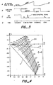
- the other mode of operation relates more to typical MS techniques where, in the Mathieu curves, ( Figure 4), a designated normal scanning line selects ions of only one mass at a time. That is, the other ions are unstable and untrappable. And then applying a voltage pulse between the end caps the trapped stable ions are ejected out of the storage region to a detector. To select a given charge to mass ratio the appropriate voltages V, U and a radio frequency (f) must be applied.
- a method of mass analyzing a sample by use of a quadrupole ion trap comprising defining a three dimensional quadrupole field in the trap in which ions of interest can be trapped, introducing sample ions into or creating sample ions in the quadrupole field whereby ions of interest are trapped, and sensing the trapped ions to provide an output signal indicative of the trapped ion mass, characterised by the steps of defining the three dimensional quadrupole field such that ions over an entire mass range of interest can be simultaneously trapped, trapping ions within the entire mass range of interest, and changing the three dimensional quadrupole field such that trapped ions of consecutive specific masses become sequentially unstable and leave the trapping field for sensing to provide output signals indicative of the ion masses.
- the invention provides a method of mass analyzing a sample which includes the step of ionizing a sample to form ions indicative of the sample constituents.
- the ions are temporarily trapped in an ion trap, for example by application of suitable d.c. and RF voltages to electrodes that provide a substantially hyperbolic electric field within the ion trap.
- the amplitude of the applied voltages can then be varied between predetermined limits such that ions of specific charge to mass ratios become sequentially and selectively unstable and exit from the ion trap.
- the unstable ions are sensed as they exit the ion trap to provide an indication of the ion masses.
- the ions can be identified by the scanning parameters at which they become unstable.
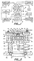
- a three dimensional ion trap is shown at 10.
- the ion trap includes a ring electrode 11, and two end caps 12 and 13 facing one another.
- a radio frequency (RF) voltage generator 14 is connected to the ring electrode 11 to supply a radio frequency (RF) voltage V sin wt between the end caps and the ring electrode which provides the quadrupole electric field for trapping ions within the ion storage region or volume 16.
- the storage region has a vertical dimension Zo and a radius r o ( Figure 1).
- the required field is formed by coupling the RF voltage between the ring electrode 11 and the two end cap electrodes 12 and 13 which as indicated are grounded.
- the symmetric fields in the ion trap 10 lead to the stability diagram shown in Figure 4.
- the ions that can be trapped depend on the numerical values of the scanning parameters. The relationship of the scanning parameters to the mass to charge ratio of the ions that are stable is described in terms of the parameters "a" and "q" in Figure 4.
- Figure 4 shows a stability diagram for the ion trap device.
- the values of a and q must be within the stability envelope if it is to be trapped within the quadrupole fields of the ion trap device.
- the type of trajectory a charged particle has in a described three dimensional quadrupole field depends on how the specific mass of the particle, m/e, and the applied field parameters, U, V, r o and w combine to map on to the stability diagram. If these scanning parameters combine to map inside the stability envelope then the given particle has a stable trajectory in the defined field. A charged particle having a stable trajectory in a three dimensional quadrupole field is constrained to an aperiodic orbit about the center of the field. Such particles can be thought of as trapped by the field. If for a particle m/e, U, V, r o and w combine to map outside the stability envelope on the stability diagram, then the given particle has an unstable trajectory in the defined field. Particles having unstable trajectories in a three dimensional quadrupole field attain displacements from the center of the field which approach infinity over time. Such particles can be thought of as escaping the field and are consequently considered untrappable.
- the locus of all possible mass to charge ratios maps onto the stability diagram as a single straight line running through the origin with a slope equal to -2UN. (This locus is also referred to as the scan line). That portion of the locus of all possible mass to charge ratios that maps within the stability region defines the range of charge to mass ratios particles may have if they are to be trapped in the applied field.
- the present invention operates a three dimensional ion trap device as a mass spectrometer based on mass selective instability, rather than mass selective detection as in Paul's resonance technique or mass selective storage as in Dawson and Whetten's technique.
- the new technique is as follows: DC and RF voltages (U, and V cos wt) are applied to a three dimensional electrode structure such that ions over the entire specific mass range of interest are simultaneously trapped within the field imposed by the electrodes. Ions are then created or introduced into the quadrupole field area by any one of a variety of well known techniques.
- the DC voltage, U, the RF voltage V, and the RF frequency, w are changed, either in combination or singly so that trapped ions of consecutive specific masses being successively unstable.
- the RF voltage V, and the RF frequency, w are changed, either in combination or singly so that trapped ions of consecutive specific masses being successively unstable.
- all such ions develop trajectories that exceed the boundaries of the trapping field.
- These ions pass out of the trapping field through perforations in the field imposing electrode structure and impinge on a detector such as an electron multiplier or a Faraday collector.
- the detected ion current signal intensity as function of time corresponds to a mass spectra of the ions that were initially trapped.
- a filament 17 which may be Rhenium, which is fed by a filament power supply 18.
- a cylindrical gate electrode and lens 19 is powered by a filament lens controller 12.
- the gate electrode provides control to gate the electron beam on and off as desired.
- End cap 12 includes an electron beam aperture 22 through which the beam projects.
- the opposite end cap 13 is perforated as illustrated at 23 to allow ions which are unstable in the fields of the ion trap to exit and be detected by an electron multiplier 24 which generates an ion signal on line 26.
- the signal on line 26 is converted from current to voltage by an electrometer 27. It is summed and stored by the unit 28 and processed in unit 29.
- Controller 31 is connected to the RF generator 14 to allow the magnitude or frequency of the RF voltage to be varied. This provides, as will be described below, for mass selection.
- the controller on the line 32 gates the filament lens controller 21 to provide an ionizing electron beam only at time periods other than the scanning interval.
- FIG. 2 illustrates in greater mechanical detail the ion trap 10, of Figure 1.
- the major structure is formed by stackable units which are made vacuum tight by O-rings at appropriate joints.
- the attached pumping unit is a high vacuum pump 33 of standard design with an inlet flange 33a. This unit should be sufficient to maintain the vacuum below 1.33x10- 4 N/m 2 (1x10⁻⁶ torr).
- the optimum pressure range of operation is 13.33 to 1.33x 10- 3 N/m 2 (1 ⁇ 10 -1 to 1x10- 5 torr) within the ion storage region. It is desirable to maintain the pressure surrounding the electron multipler below 1.33 ⁇ 10 -2 N/m 2 (1 ⁇ 10 -4 torr). This pressure differential is achieved by means of restrictive perforations 23 in the exit end cap 13.
- a retaining ring 33b which supports the pump in the mounting plate 33c.
- a cylindrical collar 34 supported on the vacuum pump flange 33 and sealed by 0-ring 36a.
- a standard high gain electron multiplier 24 having a high voltage feedthrough 37, an ion signal output feedthrough 26, and a grounding clamp 34a.
- the cathode of the electron multiplier 24 is opposite the perforations 23 in the exit end cap 13, through which pass the ejected ions.
- This exit end cap 13 is essentially a disc-like stainless steel structure which is sealed to the collar 34 by 0-ring 36b.
- a cermaic insulating ring 38 is stacked on exit end cap 13 with the associated O-ring 36c.
- a stainless steel RF ring 11 is stacked on ceramic ring 38 and sealed O-ring 36d.
- On top of RF ring 11 is a second ceramic ring 39 sealed with the 0-ring 36e.
- a cylindrical RF shield 50 is placed on outer diameter of exit end cap 13 spaced from the ceramic rings and the RF ring.
- RF power from RF generator 14, Figure 1 is applied to RF ring 11 through an opening in RF shield 50.
- the inlet end cap 12, with its electron beam aperture 22 is tacked on ceramic ring 39 and sealed by O-ring 36f.
- the cylindrical electron gate 19 is located by the lower gate insulator 19a and upper gate insulator 19b.
- the gate 19 and insulators 19a and 19b are held in position by the electron aperture lens 19c and secured by screws, one of which is shown at 19d.
- the filament assembly with dual filament 17 supported on feedthrough pins 17b carried by disc-shaped sealed base 17a is sealed to inlet end cap 12 by 0-ring 36g.
- the filament is backed by a reflector 17c mounted to the filament common feedthrough pin.
- Feedthrough pin 17b is straight and extends beyond filament to engage and apply voltage to the electron gate 19.
- a flat ring heater 51 is placed on inlet end cap 12 to heat for the ion trap device.
- the heater 51 and filament assembly base 17a are held in place by three spaced plates, one of which is shown at 42a.
- the plate 42a is secured to inlet end cap 12 by screws, one of which is shown at 42.
- a gas phase sample of a chemical compound such as the output of a gas chromatograph (GC) is inputted through the heated sample tube 43, which is sealed to the inlet end cap 12 by a ferrule 43b that is compressed by nut 43a.
- a fused quartz tubing form a GC may be threaded through the heated sample tube 43 and terminate near the ion storage region 16 of the ion trap, thus providing a method of transferring the gas phase sample from the GC to the ion trap.
- the ion storage region 16 receiving a sample from a GC may have a pressure of 13.33 to 1.33 ⁇ 10 -3 N/m 2 (1 ⁇ 10 -1 to 1 ⁇ 10 -5 torr).
- the GC may have a helium carrier gas.
- such pressure is believed to be an optimum for the operation of the present ion trap device.
- the ion storage region 16 cannot have a pressure significantly different than the pressure on the sample input line 43. If there is a pressure difference, the additional collision gas must be added to increase pressure or a sample splitter employed to reduce pressure.
- the three electrode structure in Figures 1 and 2 is operated at an initial RF voltage V, Figure 3A and a frequency, ⁇ chosen such that all ions of the specific mass range of interest may be trapped within the imposed quadrupole field.
- V, w initial field conditions
- the electron gun While maintaining the trap electrodes at this initial voltage and frequency, the electron gun is turned on, Figure 3B.
- the electron beam generated by the electron gun enters into the quadrupole field region through a small aperture 22 end cap electrode 12. These electrons collide and ionize neutral molecules residing in the trapping field region. After some time interval the electron beam is turned off and ionization within the trapping field cases. Ion species created in the trapping field region whose specific masses are less than the cut off specific mass for the trapping field very quickly (within a few hundredds of field cycles) collide with the field imposing electrodes or otherwise depart from the trapping field region.
- Ions created in the trapping field that have specific masses above the cut-off specific mass but which have trajectories which are so large as to cause them to impinge on the field imposing electrodes or otherwise leave the field region typically do so in a few hundred field cycles. Therefore several hundred field cycles after termination of ionization few stable or unstable ions are leaving the trapping field and possibly striking the detector 24 behind the lower end cap 13. However, there still remains a significant number of ions contained in the trapping field.
- the next step is to ramp the magnitude of the trapping field potential, V cos wt, Figure 3A. Of course, as the applied voltage, V, is increased, the lower limit of the range of trapped specific masses is increased.
- the time intensity profile of the signal detected at the electron multiplier, Figure 3C will correspond to a mass spectrum of the ions originally stored within the trapping field.
- the electrometer 27 converts the current signal to a voltage signal and the ion signal for a particularly scan is stored by unit 28.
- This cycle is repeated, for example, perhaps ten times per minute and unit 28 will sum together ten signals to thus significantly improve the signal-to-noise ratio.
- the RF scan rate may be increased to relatively high values to thus proportionately increase the signal-to-noise ratio.
- the summed signal is then transferred to the process unit 29.
- the summing of several scans helps to interface with the cycle rate of the gas chromatograph or other device which may typically be one per second.
- an effective online processing of the mass spectral peaks is accomplished with all the attendant benefits.
- the sensitivity and mass resolution are significantly improved by operating with a collision quenching gas such that the total pressure within the ion storage area of the device is in the range of 13.33 to 1.33x10- 3 N/ M 2 (1 ⁇ 10 -1 to 1x10- 5 torr). It is believed that the improvement results from collision of the collision gas molecules with the sample ions within the ion storage region or ion volume 16.
- the collision gas is helium.
- Other different types of inert gas molecules, such as nitrogen. Xenon or argon may also be suitable for this purpose.
- collision gases such as hydrogen, methane, ammonia and other reactive gas, including the sample itself, chemical ionization can occur in the device. It is believed that the use of a gases improves sensitivity and mass resolution even when the ion trap device is operated in more typical mass selection modes such as used by the prior art; specifically, the resonance mode or selective mass storage mode.
- the following examples are illustrative of the following examples are illustrative of the a
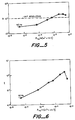
- the initial point at pressure 6.65x10- 4 N/m 2 (5 ⁇ 10 -6 torr) shows the resolution without any helium collision gas present.
- the subsequent points show that the resolution is increased with increasing collision gas pressure.
- Resolution of 1000 is achieved at a pressure of 9.31 ⁇ 10 -2 N/m 2 (7x10- 4 torr).
- Figure 6 shows the increase of intensity (I) for PFTBA mass 502 as a function of collision gas pressure. This is, of course, a measure of sensitivity.
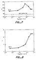
- Figures 7 and 8 show the same results for mass 69 of PFTBA.
- Figure 9 shows the mass spectrum for 2,4-dimethylphenol obtained with equipment as described operated in the scanning mode at the helium collision gas pressure of 0.27 N/m 2 (2x10⁻³ torr).
- the peak 51 represents mass 91, peak 52 mass 107 and peak 53 mass 122.
- Figure 10 shows the mass spectrum obtained at the pressure 0.27 N/m 2 (2 ⁇ 10 -3 torr) for Freon 12.
- the peak 54 represents mass 50
- peak 50 represents mass 85 and peak 56 represents mass 101.
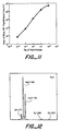
- Figure 11 shows the sensitivity and linearity of the mass spectrometer operated in accordance with the present invention.
- the area of mass peak 128 increases linearly with amount of sample from 10- 2 nanograms to 10 nanograms.
- Figure 12 shows a spectrogram taken with a device and method in accordance with the invention in which the ions are formed by chemical ionization (CI).
- the sample is H 2 0 at a pressure of 1.33 ⁇ 10 -2 N/ m 2 (1 ⁇ 10 -4 torr) with helium collision gas at 6.65 ⁇ 10 -5 N/m 2 (5 ⁇ 10 -5 torr).
- the chemical ionization of water results in H 3 0 +.
- Another beneficial fallout of operation at a relatively high pressure compared to operation at pressures of, for example, 1.33 ⁇ 10 -7 N/m 2 (1 x10- 9 torr) is that the machining tolerances in the construction of the device are not as high.
- a device in accordance with the present invention is less expensive to construct.
- the applied RF voltage is usually sinusoidal, U+V sin wt, they need only be periodic. Different stability diagrams, Figure 4, would result but would have similar characteristics and would include a scan line. Thus, the RF voltage could comprise square waves, triangular waves, etc. The quadrupole ion trap would nevertheless operate in substantially the same manner.
- ion trap sides have been described as hyperbolic. However, ion traps can be formed with cylindrical or circular trap sides.
- the method of the invention also finds use in devices such as a so-called MS/MS tandem device where two mass spectrometers are tied together in tandem.
Landscapes
- Chemical & Material Sciences (AREA)
- Analytical Chemistry (AREA)
- Electron Tubes For Measurement (AREA)
- Other Investigation Or Analysis Of Materials By Electrical Means (AREA)
Abstract
Description
- The present invention relates to a method of mass analyzing a sample by use of a quadrupole ion trap.
- An ion trap mass spectrometer (MS) is described in US-A-2939952 (Paul). A hyperbolic electric field provides an ion storage region by the use of either a hyperpolic electrode structure or a spherical electrode structure which provides an equivalent hyperbolic trapping field.
- A more standard type of mass spectrometer uses a quadrupole filter which consists of four cylindrical rods.
- In the past, the ion trap MS has been operated in a mode very similar to conventional quadrupole mass spectrometers where only one nominal mass is trapped at one time and then sensed.
- However, because of difficulties related to general performance of this type of spectrometer it has not been commercially successful.
- In the introduction to the book "Quadrupole Mass Spectrometry and its Applications", edited by P. H. Dawson, published by Elsevier, Amsterdam, 1976, pages 4-6, Dawson characterized the development and future of ion trap mass spectrometer technology as follows:
- The quadrupole ion trap represents a rather special case. The three dimensional quadrupole field was described in the original Paul patents and the feasibility of the principle of ion storage was demonstrated by Berkling and Fischer. However, not much attention was paid to the development of this unusual device. It was very soon applied by Wuerker et al to trap macroscopic particles and by Dehmelt to confine ions in order to perform spectroscopic measurements. The application to gas analysis did not progress until the publication by Rettinghaus in 1967 and then the extensive investigations of Dawson and Whetten beginning in 1968 marked the awakening of a much wider interest. (See Chapters VIII and X for the application to atomic and molecular physics). The importance of the trapping technique may well lie mainly in its specialized applications.
- In this same book (page 181) in a chapter entitled "Quadrupole Ion Traps" authored by Todd, Lawson and Bonnerthefollowing is stated:
- "The three electrode ion trap was, of course, first developed for use as a mass spectrometer and this is the chief application to which the device has been put. Despite this attenion, however, no manufacturer has thought fit to develop the trap as a commercially available instrument".
- This book was pubished more than 16 years after the basic ion trap patent to Paul was issued in 1960.
- Mass storage is achieved by operating the trap electrodes with values of RF voltage V, and frequency, f, d.c. voltage, U, and device size ro, such that ions with a range of charge to mass ratio values are stably trapped within the device. These parameters will be referred to as scanning parameters and have a fixed relationship to the trapped masses. For stable ions there exists a distinctive secular frequency for each value of charge to mass. For detection of the ions these frequencies can be determined by a frequency tuned circuit which couples to the oscillating motion of the ions within the trap, and then by use of analyzing techniques charge to mass ratio may be determined.
- The other mode of operation, the ion storage mode, relates more to typical MS techniques where, in the Mathieu curves, (Figure 4), a designated normal scanning line selects ions of only one mass at a time. That is, the other ions are unstable and untrappable. And then applying a voltage pulse between the end caps the trapped stable ions are ejected out of the storage region to a detector. To select a given charge to mass ratio the appropriate voltages V, U and a radio frequency (f) must be applied.
- Thus, in summary, as pointed out by the quoted text above, no commercial ion traps have yet been built. And this is because these mass selection techniques are inefficient, difficult to impent, and yield poor mass resolution and limited mass range. These are all relative to the more standard quadrupole mass filter methods and apparatus.
- According to this invention there is provided a method of mass analyzing a sample by use of a quadrupole ion trap, comprising defining a three dimensional quadrupole field in the trap in which ions of interest can be trapped, introducing sample ions into or creating sample ions in the quadrupole field whereby ions of interest are trapped, and sensing the trapped ions to provide an output signal indicative of the trapped ion mass, characterised by the steps of defining the three dimensional quadrupole field such that ions over an entire mass range of interest can be simultaneously trapped, trapping ions within the entire mass range of interest, and changing the three dimensional quadrupole field such that trapped ions of consecutive specific masses become sequentially unstable and leave the trapping field for sensing to provide output signals indicative of the ion masses.
- The invention provides a method of mass analyzing a sample which includes the step of ionizing a sample to form ions indicative of the sample constituents. The ions are temporarily trapped in an ion trap, for example by application of suitable d.c. and RF voltages to electrodes that provide a substantially hyperbolic electric field within the ion trap. The amplitude of the applied voltages can then be varied between predetermined limits such that ions of specific charge to mass ratios become sequentially and selectively unstable and exit from the ion trap. The unstable ions are sensed as they exit the ion trap to provide an indication of the ion masses. The ions can be identified by the scanning parameters at which they become unstable.
- This invention will now be described by way of example with reference to the drawings, in which:-
- Figure 1 is a simplified schematic of a quadrupole ion trap which can utilise the method of the invention, along with a block diagram of the associated electrical circuits;
- Figure 2 is a cross-sectional view of a complete quadrupole ion trap which can utilise the method of the invention;
- Figure 3 is a timing diagram illustrating operation of the ion trap of Figure 2 as a scanning mass spectrometer;
- Figure 4 illustrates a stability envelope for an ion trap as shown in Figures 1 and 2;
- Figure 5 is a curve showing mass resolution as a function of pressure for a trap operated in accordance with the method of the invention;
- Figure 6 is a curve showing the increase of ion signal intensity (I) as a function of collision gas pressure for a trap operated in accordance with the method of the invention;
- Figure 7 is a curve showing mass resolution as a function of pressure for a trap operated in accordance with the method of the invention;
- Figure 8 is a curve showing the increase of intensity (I) as a function of collision gas pressure for a trap operated in accordance with the method of the invention;
- Figure 9 is a mass spectrogram of 2,4-dimethylphenol taken with a trap operated in accordance with the method of the invention;
- Figure 10 is a mass spectrogram of Freon 12 taken with a trap operated in accordance with the method of the invention;
- Figure 11 shows the sensitivity and linearity of a trap operated in accordance with the method of the invention for different amounts of naphthalene; and
- Figure 12 shows the spectrogram for chemically ionized
H 20. - Referring first to Figure 1, a three dimensional ion trap is shown at 10. The ion trap includes a ring electrode 11, and two
end caps voltage generator 14 is connected to the ring electrode 11 to supply a radio frequency (RF) voltage V sin wt between the end caps and the ring electrode which provides the quadrupole electric field for trapping ions within the ion storage region orvolume 16. The storage region has a vertical dimension Zo and a radius ro (Figure 1). The required field is formed by coupling the RF voltage between the ring electrode 11 and the twoend cap electrodes ion trap 10 lead to the stability diagram shown in Figure 4. The ions that can be trapped depend on the numerical values of the scanning parameters. The relationship of the scanning parameters to the mass to charge ratio of the ions that are stable is described in terms of the parameters "a" and "q" in Figure 4. - These parameters are defined as:


- V=magnitude of radio frequency (RF) voltage
- U=amplitude of applied direct current (d.c.) voltage
- e=charge on charged particle
- m=mass of charged particle
- r.=distance of ring electrode from center of a three dimensional quadrupole electrode structure symmetry axis
- zo=ro/√2
- ω=2πf
- f=frequency of RF voltage
- Figure 4 shows a stability diagram for the ion trap device. For any particular ion, the values of a and q must be within the stability envelope if it is to be trapped within the quadrupole fields of the ion trap device.
- The type of trajectory a charged particle has in a described three dimensional quadrupole field depends on how the specific mass of the particle, m/e, and the applied field parameters, U, V, ro and w combine to map on to the stability diagram. If these scanning parameters combine to map inside the stability envelope then the given particle has a stable trajectory in the defined field. A charged particle having a stable trajectory in a three dimensional quadrupole field is constrained to an aperiodic orbit about the center of the field. Such particles can be thought of as trapped by the field. If for a particle m/e, U, V, ro and w combine to map outside the stability envelope on the stability diagram, then the given particle has an unstable trajectory in the defined field. Particles having unstable trajectories in a three dimensional quadrupole field attain displacements from the center of the field which approach infinity over time. Such particles can be thought of as escaping the field and are consequently considered untrappable.
- For a three dimensional quadrupole field defined by U, V, r. and w, the locus of all possible mass to charge ratios maps onto the stability diagram as a single straight line running through the origin with a slope equal to -2UN. (This locus is also referred to as the scan line). That portion of the locus of all possible mass to charge ratios that maps within the stability region defines the range of charge to mass ratios particles may have if they are to be trapped in the applied field. By properly choosing the magnitudes of U and V, the range of specific masses of trappable particles can be selected. If the ratio of U to V is chosen so that the locus of possible specific masses maps through an apex of the stability region (Figure 4, item a) then only particles within a very narrow range of specific masses will have stable trajectories. However, if the ratio of U to V is chosen so that the locus of possible specific masses maps through the middle of the stability region (Figure 4, item b) then particles of a broad range of specific masses will have stable trajectories.
- The present invention operates a three dimensional ion trap device as a mass spectrometer based on mass selective instability, rather than mass selective detection as in Paul's resonance technique or mass selective storage as in Dawson and Whetten's technique. In general terms the new technique is as follows: DC and RF voltages (U, and V cos wt) are applied to a three dimensional electrode structure such that ions over the entire specific mass range of interest are simultaneously trapped within the field imposed by the electrodes. Ions are then created or introduced into the quadrupole field area by any one of a variety of well known techniques. After this storage period, the DC voltage, U, the RF voltage V, and the RF frequency, w, are changed, either in combination or singly so that trapped ions of consecutive specific masses being successively unstable. As each trapped ionic species becomes unstable, all such ions develop trajectories that exceed the boundaries of the trapping field. These ions pass out of the trapping field through perforations in the field imposing electrode structure and impinge on a detector such as an electron multiplier or a Faraday collector. The detected ion current signal intensity as function of time corresponds to a mass spectra of the ions that were initially trapped.
- Referring back to Figure 1, to provide an ionizing electron beam for ionizing the sample molecules which are introduced into the
ion storage region 16, there is afilament 17 which may be Rhenium, which is fed by afilament power supply 18. A cylindrical gate electrode andlens 19 is powered by afilament lens controller 12. The gate electrode provides control to gate the electron beam on and off as desired.End cap 12 includes anelectron beam aperture 22 through which the beam projects. Theopposite end cap 13 is perforated as illustrated at 23 to allow ions which are unstable in the fields of the ion trap to exit and be detected by anelectron multiplier 24 which generates an ion signal online 26. The signal online 26 is converted from current to voltage by anelectrometer 27. It is summed and stored by theunit 28 and processed inunit 29.Controller 31 is connected to theRF generator 14 to allow the magnitude or frequency of the RF voltage to be varied. This provides, as will be described below, for mass selection. The controller on theline 32 gates thefilament lens controller 21 to provide an ionizing electron beam only at time periods other than the scanning interval. - Figure 2 illustrates in greater mechanical detail the
ion trap 10, of Figure 1. The major structure is formed by stackable units which are made vacuum tight by O-rings at appropriate joints. The attached pumping unit is ahigh vacuum pump 33 of standard design with an inlet flange 33a. This unit should be sufficient to maintain the vacuum below 1.33x10⁻⁴ N/m2 (1x10⁻⁶ torr). As discussed below, the optimum pressure range of operation is 13.33 to 1.33x 10⁻³ N/m2 (1 × 10⁻¹ to 1x10⁻⁵ torr) within the ion storage region. It is desirable to maintain the pressure surrounding the electron multipler below 1.33×10⁻² N/m2 (1×10⁻⁴ torr). This pressure differential is achieved by means ofrestrictive perforations 23 in theexit end cap 13. Attached in a groove at the outside diameter of the pump flange is a retainingring 33b which supports the pump in the mountingplate 33c. Next in the stack is acylindrical collar 34 supported on thevacuum pump flange 33 and sealed by 0-ring 36a. Withincollar 34 is a standard highgain electron multiplier 24 having ahigh voltage feedthrough 37, an ionsignal output feedthrough 26, and agrounding clamp 34a. The cathode of theelectron multiplier 24 is opposite theperforations 23 in theexit end cap 13, through which pass the ejected ions. Thisexit end cap 13 is essentially a disc-like stainless steel structure which is sealed to thecollar 34 by 0-ring 36b. A cermaic insulatingring 38 is stacked onexit end cap 13 with the associated O-ring 36c. A stainless steel RF ring 11 is stacked onceramic ring 38 and sealed O-ring 36d. On top of RF ring 11 is a secondceramic ring 39 sealed with the 0-ring 36e. Acylindrical RF shield 50 is placed on outer diameter ofexit end cap 13 spaced from the ceramic rings and the RF ring. RF power fromRF generator 14, Figure 1, is applied to RF ring 11 through an opening inRF shield 50. Finally, theinlet end cap 12, with itselectron beam aperture 22 is tacked onceramic ring 39 and sealed by O-ring 36f. In the central cavity ofinlet end cap 12, thecylindrical electron gate 19 is located by thelower gate insulator 19a and upper gate insulator 19b. Thegate 19 andinsulators 19a and 19b are held in position by theelectron aperture lens 19c and secured by screws, one of which is shown at 19d. - Next the filament assembly with
dual filament 17 supported onfeedthrough pins 17b carried by disc-shaped sealed base 17a is sealed toinlet end cap 12 by 0-ring 36g. The filament is backed by areflector 17c mounted to the filament common feedthrough pin.Feedthrough pin 17b is straight and extends beyond filament to engage and apply voltage to theelectron gate 19. Aflat ring heater 51 is placed oninlet end cap 12 to heat for the ion trap device. Theheater 51 and filament assembly base 17a are held in place by three spaced plates, one of which is shown at 42a. The plate 42a is secured toinlet end cap 12 by screws, one of which is shown at 42. In addition to the vacuum produced bypump 33, inherently pulling the stacked structure together, it is also held together with the components being in face-to-face contact for tolerance purposes, by four studs, one of which is shown at 41, and nuts shown at 41 a. Thestuds 41 extend throughinlet end cap 12 into the mountingplate 33c allowing a compressive load across the entire stacked structure. - A gas phase sample of a chemical compound such as the output of a gas chromatograph (GC) is inputted through the
heated sample tube 43, which is sealed to theinlet end cap 12 by aferrule 43b that is compressed by nut 43a. A fused quartz tubing form a GC may be threaded through theheated sample tube 43 and terminate near theion storage region 16 of the ion trap, thus providing a method of transferring the gas phase sample from the GC to the ion trap. - The
ion storage region 16 receiving a sample from a GC, may have a pressure of 13.33 to 1.33×10⁻³ N/m2 (1×10⁻¹ to 1×10⁻⁵ torr). In addition, the GC may have a helium carrier gas. Moreover, such pressure is believed to be an optimum for the operation of the present ion trap device. Naturally, theion storage region 16 cannot have a pressure significantly different than the pressure on thesample input line 43. If there is a pressure difference, the additional collision gas must be added to increase pressure or a sample splitter employed to reduce pressure. - However, ideally it is desired that there be a continuous online operation between the GC and the ion trap.
- Thus, in summary, with the stacked structure shown in Figure 2, no external vacuum type manifold enclosure is necessary. Also, the structure may be easily disassembled for cleaning when appropriate.
- The three electrode structure in Figures 1 and 2 is operated at an initial RF voltage V, Figure 3A and a frequency, ω chosen such that all ions of the specific mass range of interest may be trapped within the imposed quadrupole field. This means that for these initial field conditions (V, w) masses in the range of interest must map into the stable region of the stability diagram. Since in this example no d.c. voltage is applied between the ring and end cap electrode (Us=0), the containing field is purely oscillatory (RF only). This means that the locus of possible specific masses maps directly into the qz axis on the stability diagram. Referring to Figure 4 it can be seen that ions with specific masses mapping between q==o and Qz=qcut off (~.91) may potentially be trapped in the quadrupole field region. Since the stability parameter qz varies inversely with specific mass, this means for RF only operation all specific masses greater than the threshold specific mass that maps into qcut off are trappable. Thus, in this example the initial trap operating voltage and frequency Vs and w are chosen such that all ions of interest have specific masses greater than the initial threshold specific mass, m/e, that maps to qcut off.
- While maintaining the trap electrodes at this initial voltage and frequency, the electron gun is turned on, Figure 3B. The electron beam generated by the electron gun enters into the quadrupole field region through a
small aperture 22end cap electrode 12. These electrons collide and ionize neutral molecules residing in the trapping field region. After some time interval the electron beam is turned off and ionization within the trapping field cases. Ion species created in the trapping field region whose specific masses are less than the cut off specific mass for the trapping field very quickly (within a few hundredds of field cycles) collide with the field imposing electrodes or otherwise depart from the trapping field region. Ions created in the trapping field that have specific masses above the cut-off specific mass but which have trajectories which are so large as to cause them to impinge on the field imposing electrodes or otherwise leave the field region typically do so in a few hundred field cycles. Therefore several hundred field cycles after termination of ionization few stable or unstable ions are leaving the trapping field and possibly striking thedetector 24 behind thelower end cap 13. However, there still remains a significant number of ions contained in the trapping field. The next step is to ramp the magnitude of the trapping field potential, V cos wt, Figure 3A. Of course, as the applied voltage, V, is increased, the lower limit of the range of trapped specific masses is increased. - Hence, as the applied RF voltage V increases, stored ions become sequentially unstable in order of increasing specific mass. Ions that become sequentially unstable during this voltage change, do so primarily in the axial direction of motion. This means that as trapped ions attain instability because of the changing trapping field intensity, they rapidly depart the trapping field region in the direction of one or the other end cap electrodes. Since the lower end cap electrode in the device shown in Figures 1 and 2 is perforated, a significant percentage of unstable ions transmit through this electrode and strike the
detector 24. If the change sweep rate of the RF voltage is chosen so that ions of consecutive specific masses are not made unstable at a rate faster than the rate at which unstable ions depart the trapping field region, the time intensity profile of the signal detected at the electron multiplier, Figure 3C, will correspond to a mass spectrum of the ions originally stored within the trapping field. - In the above example the three dimensional ion trap electrodes were driven with a purely RF voltage, and the magnitude of that voltage was changed. However, the basic technique applies equally well to situations where there is an applied d.c. voltage U, in addition to the RF voltage, V, between the ring electrode and the end cap electrodes. Such operation would just place an upper limit on the range of specific masses that may be mass analyzed in a given experiment. While maintaining a constant ratio between the applied RF and d.c. potentials (U and V) is convenient, in that the magnitudes of the voltages relate linearly to the specific mass of the detected ions, it is not inherent in the technique. While changing one or both of the applied d.c. and RF voltages to mass sequentially destabilize ions is easy to implement, there is no theoretical reason why one shouldn't manipulate the frequency, ω, U and V to accomplish the same thing. While it is convenient from the standpoint of ion collection and detection to have specific mass selected ions become unstable in the axial direction, a three electrode trap operating according to the described principle could be operated so that mass selected ions would have unstable trajectories in the radial directions and reach a detector by transmitting through the ring electrode.
- Referring again to Figure 1, the
electrometer 27 converts the current signal to a voltage signal and the ion signal for a particularly scan is stored byunit 28. This cycle is repeated, for example, perhaps ten times per minute andunit 28 will sum together ten signals to thus significantly improve the signal-to-noise ratio. Thus, with the ability to sum as many scans as is necessary, the RF scan rate may be increased to relatively high values to thus proportionately increase the signal-to-noise ratio. The summed signal is then transferred to theprocess unit 29. In addition to improving the signal-to-noise ratio, the summing of several scans helps to interface with the cycle rate of the gas chromatograph or other device which may typically be one per second. Thus, an effective online processing of the mass spectral peaks is accomplished with all the attendant benefits. - The sensitivity and mass resolution are significantly improved by operating with a collision quenching gas such that the total pressure within the ion storage area of the device is in the range of 13.33 to 1.33x10⁻³ N/M 2 (1×10⁻¹ to 1x10⁻⁵ torr). It is believed that the improvement results from collision of the collision gas molecules with the sample ions within the ion storage region or
ion volume 16. Preferably the collision gas is helium. Other different types of inert gas molecules, such as nitrogen. Xenon or argon, may also be suitable for this purpose. For collision gases such as hydrogen, methane, ammonia and other reactive gas, including the sample itself, chemical ionization can occur in the device. It is believed that the use of a gases improves sensitivity and mass resolution even when the ion trap device is operated in more typical mass selection modes such as used by the prior art; specifically, the resonance mode or selective mass storage mode. The following examples are illustrative of the - increased mass resolution and sensitivity of the ion trap device.
- Figure 5 shows the mass resolution, R, as a function of pressure for perfluorotributylamine (PFTBA) mass 502 where R=(M/6m) is taken at full width half height (FWHH). The initial point at pressure 6.65x10⁻⁴ N/m2 (5×10⁻⁶ torr) shows the resolution without any helium collision gas present. The subsequent points show that the resolution is increased with increasing collision gas pressure. Resolution of 1000 is achieved at a pressure of 9.31 ×10⁻² N/m2 (7x10⁻⁴ torr). Figure 6 shows the increase of intensity (I) for PFTBA mass 502 as a function of collision gas pressure. This is, of course, a measure of sensitivity. The curves of Figures 7 and 8 show the same results for mass 69 of PFTBA. Figure 9 shows the mass spectrum for 2,4-dimethylphenol obtained with equipment as described operated in the scanning mode at the helium collision gas pressure of 0.27 N/m2 (2x10⁻³ torr). The
peak 51 representsmass 91,peak 52mass 107 and peak 53mass 122. Figure 10 shows the mass spectrum obtained at the pressure 0.27 N/m2 (2×10⁻³ torr) forFreon 12. Thepeak 54 representsmass 50,peak 50 representsmass 85 andpeak 56 representsmass 101. Figure 11 shows the sensitivity and linearity of the mass spectrometer operated in accordance with the present invention. The area ofmass peak 128 increases linearly with amount of sample from 10-2 nanograms to 10 nanograms. The extreme sensitivity is also to be noted. Figure 12 shows a spectrogram taken with a device and method in accordance with the invention in which the ions are formed by chemical ionization (CI). The sample isH 20 at a pressure of 1.33×10⁻² N/ m2 (1×10⁻⁴ torr) with helium collision gas at 6.65×10⁻⁵ N/m2 (5×10⁻⁵ torr). The chemical ionization of water results inH 30+. - Another beneficial fallout of operation at a relatively high pressure compared to operation at pressures of, for example, 1.33×10⁻⁷ N/m2 (1 x10⁻⁹ torr) is that the machining tolerances in the construction of the device are not as high. Thus, a device in accordance with the present invention is less expensive to construct.
- Although the applied RF voltage is usually sinusoidal, U+V sin wt, they need only be periodic. Different stability diagrams, Figure 4, would result but would have similar characteristics and would include a scan line. Thus, the RF voltage could comprise square waves, triangular waves, etc. The quadrupole ion trap would nevertheless operate in substantially the same manner.
- The preferable ion trap sides have been described as hyperbolic. However, ion traps can be formed with cylindrical or circular trap sides.
- The method of the invention also finds use in devices such as a so-called MS/MS tandem device where two mass spectrometers are tied together in tandem.
Claims (10)
Priority Applications (1)
| Application Number | Priority Date | Filing Date | Title |
|---|---|---|---|
| AT83307458T ATE43753T1 (en) | 1982-12-29 | 1983-12-07 | PROCEDURE FOR DETERMINING THE MASS OF A SAMPLE BY A QUADRUPOLE ION BUSTER. |
Applications Claiming Priority (2)
| Application Number | Priority Date | Filing Date | Title |
|---|---|---|---|
| US06/454,351 US4540884A (en) | 1982-12-29 | 1982-12-29 | Method of mass analyzing a sample by use of a quadrupole ion trap |
| US454351 | 1982-12-29 |
Publications (3)
| Publication Number | Publication Date |
|---|---|
| EP0113207A2 EP0113207A2 (en) | 1984-07-11 |
| EP0113207A3 EP0113207A3 (en) | 1986-02-05 |
| EP0113207B1 true EP0113207B1 (en) | 1989-05-31 |
Family
ID=23804267
Family Applications (1)
| Application Number | Title | Priority Date | Filing Date |
|---|---|---|---|
| EP83307458A Expired EP0113207B1 (en) | 1982-12-29 | 1983-12-07 | Method of mass analyzing a sample by use of a quadrupole ion trap |
Country Status (8)
| Country | Link |
|---|---|
| US (1) | US4540884A (en) |
| EP (1) | EP0113207B1 (en) |
| JP (1) | JPS6032310B2 (en) |
| AT (1) | ATE43753T1 (en) |
| AU (1) | AU568615B2 (en) |
| CA (1) | CA1207918A (en) |
| DE (1) | DE3380001D1 (en) |
| ZA (1) | ZA839039B (en) |
Cited By (1)
| Publication number | Priority date | Publication date | Assignee | Title |
|---|---|---|---|---|
| DE10027545C1 (en) * | 2000-06-02 | 2001-10-31 | Bruker Daltonik Gmbh | Ion filling regulation method for HF quadrupole ion trap mass spectrometer calculates actual filling level for comparison with required filling level for regulation of ion filling |
Families Citing this family (201)
| Publication number | Priority date | Publication date | Assignee | Title |
|---|---|---|---|---|
| DE3335625A1 (en) * | 1983-09-30 | 1985-04-11 | Siemens AG, 1000 Berlin und 8000 München | METHOD AND DEVICE FOR STORING THE MEASURED DATA FROM PARTIAL AREAS OF A SPUTTER CRATER, WHICH IS GENERATED AND ANALYZED IN A SECOND EDITION MASS SPECTROMETER |
| US4650999A (en) * | 1984-10-22 | 1987-03-17 | Finnigan Corporation | Method of mass analyzing a sample over a wide mass range by use of a quadrupole ion trap |
| US4588888A (en) * | 1985-02-11 | 1986-05-13 | Nicolet Instrument Corporation | Mass spectrometer having magnetic trapping |
| DE3688215T3 (en) * | 1985-05-24 | 2005-08-25 | Thermo Finnigan Llc, San Jose | Control method for an ion trap. |
| JP2679026B2 (en) * | 1985-08-21 | 1997-11-19 | 株式会社島津製作所 | Mass spectrometer |
| US4686367A (en) * | 1985-09-06 | 1987-08-11 | Finnigan Corporation | Method of operating quadrupole ion trap chemical ionization mass spectrometry |
| DE3533364A1 (en) * | 1985-09-19 | 1987-03-26 | Bruker Franzen Analytik Gmbh | METHOD AND DEVICE FOR EXAMINING A GAS MIXTURE |
| DE3575362D1 (en) * | 1985-10-12 | 1990-02-15 | Leybold Ag | METHOD AND DEVICE FOR CHECKING THE MEASURING SIGNAL PATH OF A MEASURING DEVICE. |
| JPH07114120B2 (en) * | 1985-12-06 | 1995-12-06 | 株式会社島津製作所 | Mass spectrometer |
| US5107109A (en) * | 1986-03-07 | 1992-04-21 | Finnigan Corporation | Method of increasing the dynamic range and sensitivity of a quadrupole ion trap mass spectrometer |
| US4761545A (en) * | 1986-05-23 | 1988-08-02 | The Ohio State University Research Foundation | Tailored excitation for trapped ion mass spectrometry |
| US4749860A (en) * | 1986-06-05 | 1988-06-07 | Finnigan Corporation | Method of isolating a single mass in a quadrupole ion trap |
| US4755670A (en) * | 1986-10-01 | 1988-07-05 | Finnigan Corporation | Fourtier transform quadrupole mass spectrometer and method |
| GB8625529D0 (en) * | 1986-10-24 | 1986-11-26 | Griffiths I W | Control/analysis of charged particles |
| US4771172A (en) * | 1987-05-22 | 1988-09-13 | Finnigan Corporation | Method of increasing the dynamic range and sensitivity of a quadrupole ion trap mass spectrometer operating in the chemical ionization mode |
| US4818869A (en) * | 1987-05-22 | 1989-04-04 | Finnigan Corporation | Method of isolating a single mass or narrow range of masses and/or enhancing the sensitivity of an ion trap mass spectrometer |
| EP0321819B2 (en) * | 1987-12-23 | 2002-06-19 | Bruker Daltonik GmbH | Method for the massspectrometric analysis of a gas mixture, and mass sprectrometer for carrying out the method |
| ATE99834T1 (en) * | 1988-04-13 | 1994-01-15 | Bruker Franzen Analytik Gmbh | METHOD FOR MASS ANALYSIS OF A SAMPLE USING A QUISTOR AND QUISTOR DEVELOPED FOR CARRYING OUT THIS PROCEDURE. |
| JPH02103856A (en) * | 1988-06-03 | 1990-04-16 | Finnigan Corp | Operation of ion-trapping type mass-spectrometer |
| US4833394A (en) * | 1988-06-07 | 1989-05-23 | Oak Ridge Associated Universities, Inc. | Ion beam profile analyzer with noise compensation |
| US4878014A (en) * | 1988-06-07 | 1989-10-31 | Oak Ridge Associated Universities | Ion beam profile scanner having symmetric detector surface to minimize capacitance noise |
| EP0362432A1 (en) * | 1988-10-07 | 1990-04-11 | Bruker Franzen Analytik GmbH | Improvement of a method of mass analyzing a sample |
| EP0383961B1 (en) * | 1989-02-18 | 1994-02-23 | Bruker Franzen Analytik GmbH | Method and instrument for mass analyzing samples with a quistor |
| US4945234A (en) * | 1989-05-19 | 1990-07-31 | Extrel Ftms, Inc. | Method and apparatus for producing an arbitrary excitation spectrum for Fourier transform mass spectrometry |
| US4931640A (en) * | 1989-05-19 | 1990-06-05 | Marshall Alan G | Mass spectrometer with reduced static electric field |
| US5051582A (en) * | 1989-09-06 | 1991-09-24 | The United States Of America As Represented By The Secretary Of The Air Force | Method for the production of size, structure and composition of specific-cluster ions |
| US5118950A (en) * | 1989-12-29 | 1992-06-02 | The United States Of America As Represented By The Secretary Of The Air Force | Cluster ion synthesis and confinement in hybrid ion trap arrays |
| US5075547A (en) * | 1991-01-25 | 1991-12-24 | Finnigan Corporation | Quadrupole ion trap mass spectrometer having two pulsed axial excitation input frequencies and method of parent and neutral loss scanning and selected reaction monitoring |
| US5128542A (en) * | 1991-01-25 | 1992-07-07 | Finnigan Corporation | Method of operating an ion trap mass spectrometer to determine the resonant frequency of trapped ions |
| US5256875A (en) * | 1992-05-14 | 1993-10-26 | Teledyne Mec | Method for generating filtered noise signal and broadband signal having reduced dynamic range for use in mass spectrometry |
| US5274233A (en) * | 1991-02-28 | 1993-12-28 | Teledyne Mec | Mass spectrometry method using supplemental AC voltage signals |
| US5200613A (en) * | 1991-02-28 | 1993-04-06 | Teledyne Mec | Mass spectrometry method using supplemental AC voltage signals |
| US5449905A (en) * | 1992-05-14 | 1995-09-12 | Teledyne Et | Method for generating filtered noise signal and broadband signal having reduced dynamic range for use in mass spectrometry |
| US5196699A (en) * | 1991-02-28 | 1993-03-23 | Teledyne Mec | Chemical ionization mass spectrometry method using notch filter |
| US5134286A (en) * | 1991-02-28 | 1992-07-28 | Teledyne Cme | Mass spectrometry method using notch filter |
| US5173604A (en) * | 1991-02-28 | 1992-12-22 | Teledyne Cme | Mass spectrometry method with non-consecutive mass order scan |
| US5381007A (en) * | 1991-02-28 | 1995-01-10 | Teledyne Mec A Division Of Teledyne Industries, Inc. | Mass spectrometry method with two applied trapping fields having same spatial form |
| US5451782A (en) * | 1991-02-28 | 1995-09-19 | Teledyne Et | Mass spectometry method with applied signal having off-resonance frequency |
| US5206507A (en) * | 1991-02-28 | 1993-04-27 | Teledyne Mec | Mass spectrometry method using filtered noise signal |
| US5182451A (en) * | 1991-04-30 | 1993-01-26 | Finnigan Corporation | Method of operating an ion trap mass spectrometer in a high resolution mode |
| US5248883A (en) * | 1991-05-30 | 1993-09-28 | International Business Machines Corporation | Ion traps of mono- or multi-planar geometry and planar ion trap devices |
| US5179278A (en) * | 1991-08-23 | 1993-01-12 | Mds Health Group Limited | Multipole inlet system for ion traps |
| US5272337A (en) * | 1992-04-08 | 1993-12-21 | Martin Marietta Energy Systems, Inc. | Sample introducing apparatus and sample modules for mass spectrometer |
| US5397894A (en) * | 1993-05-28 | 1995-03-14 | Varian Associates, Inc. | Method of high mass resolution scanning of an ion trap mass spectrometer |
| US5521380A (en) | 1992-05-29 | 1996-05-28 | Wells; Gregory J. | Frequency modulated selected ion species isolation in a quadrupole ion trap |
| US5479012A (en) * | 1992-05-29 | 1995-12-26 | Varian Associates, Inc. | Method of space charge control in an ion trap mass spectrometer |
| GB2267385B (en) * | 1992-05-29 | 1995-12-13 | Finnigan Corp | Method of detecting the ions in an ion trap mass spectrometer |
| US5300772A (en) * | 1992-07-31 | 1994-04-05 | Varian Associates, Inc. | Quadruple ion trap method having improved sensitivity |
| US5378891A (en) * | 1993-05-27 | 1995-01-03 | Varian Associates, Inc. | Method for selective collisional dissociation using border effect excitation with prior cooling time control |
| US5399857A (en) * | 1993-05-28 | 1995-03-21 | The Johns Hopkins University | Method and apparatus for trapping ions by increasing trapping voltage during ion introduction |
| DE4324233C1 (en) * | 1993-07-20 | 1995-01-19 | Bruker Franzen Analytik Gmbh | Procedure for the selection of the reaction pathways in ion traps |
| DE4324224C1 (en) * | 1993-07-20 | 1994-10-06 | Bruker Franzen Analytik Gmbh | Quadrupole ion traps with switchable multipole components |
| DE4326549C1 (en) * | 1993-08-07 | 1994-08-25 | Bruker Franzen Analytik Gmbh | Method for a regulation of the space charge in ion traps |
| US5543625A (en) * | 1994-05-20 | 1996-08-06 | Finnigan Corporation | Filament assembly for mass spectrometer ion sources |
| US5420425A (en) * | 1994-05-27 | 1995-05-30 | Finnigan Corporation | Ion trap mass spectrometer system and method |
| JP3240857B2 (en) * | 1994-10-11 | 2001-12-25 | 株式会社日立製作所 | Plasma ion mass spectrometer and plasma ion mass spectrometry method |
| US5572022A (en) * | 1995-03-03 | 1996-11-05 | Finnigan Corporation | Method and apparatus of increasing dynamic range and sensitivity of a mass spectrometer |
| JP3509267B2 (en) * | 1995-04-03 | 2004-03-22 | 株式会社日立製作所 | Ion trap mass spectrometry method and apparatus |
| US5783824A (en) * | 1995-04-03 | 1998-07-21 | Hitachi, Ltd. | Ion trapping mass spectrometry apparatus |
| JP3495512B2 (en) * | 1996-07-02 | 2004-02-09 | 株式会社日立製作所 | Ion trap mass spectrometer |
| US5572025A (en) * | 1995-05-25 | 1996-11-05 | The Johns Hopkins University, School Of Medicine | Method and apparatus for scanning an ion trap mass spectrometer in the resonance ejection mode |
| JPH095298A (en) * | 1995-06-06 | 1997-01-10 | Varian Assoc Inc | Method of detecting kind of selected ion in quadrupole ion trap |
| US5576540A (en) * | 1995-08-11 | 1996-11-19 | Mds Health Group Limited | Mass spectrometer with radial ejection |
| US5942752A (en) * | 1996-05-17 | 1999-08-24 | Hewlett-Packard Company | Higher pressure ion source for two dimensional radio-frequency quadrupole electric field for mass spectrometer |
| US5696376A (en) * | 1996-05-20 | 1997-12-09 | The Johns Hopkins University | Method and apparatus for isolating ions in an ion trap with increased resolving power |
| JP3294106B2 (en) * | 1996-05-21 | 2002-06-24 | 株式会社日立製作所 | Three-dimensional quadrupole mass spectrometry and apparatus |
| US5756996A (en) * | 1996-07-05 | 1998-05-26 | Finnigan Corporation | Ion source assembly for an ion trap mass spectrometer and method |
| JP3624419B2 (en) * | 1996-09-13 | 2005-03-02 | 株式会社日立製作所 | Mass spectrometer |
| US5793038A (en) * | 1996-12-10 | 1998-08-11 | Varian Associates, Inc. | Method of operating an ion trap mass spectrometer |
| JP3617662B2 (en) † | 1997-02-28 | 2005-02-09 | 株式会社島津製作所 | Mass spectrometer |
| US6147348A (en) * | 1997-04-11 | 2000-11-14 | University Of Florida | Method for performing a scan function on quadrupole ion trap mass spectrometers |
| JP3570151B2 (en) * | 1997-04-17 | 2004-09-29 | 株式会社日立製作所 | Ion trap mass spectrometer |
| US6140638A (en) * | 1997-06-04 | 2000-10-31 | Mds Inc. | Bandpass reactive collision cell |
| US6034768A (en) * | 1997-09-26 | 2000-03-07 | Physical Sciences Inc. | Induced breakdown spectroscopy detector system with controllable delay time |
| DE19751401B4 (en) * | 1997-11-20 | 2007-03-01 | Bruker Daltonik Gmbh | Quadrupole radio frequency ion traps for mass spectrometers |
| US6124592A (en) * | 1998-03-18 | 2000-09-26 | Technispan Llc | Ion mobility storage trap and method |
| US6392225B1 (en) | 1998-09-24 | 2002-05-21 | Thermo Finnigan Llc | Method and apparatus for transferring ions from an atmospheric pressure ion source into an ion trap mass spectrometer |
| US6124591A (en) * | 1998-10-16 | 2000-09-26 | Finnigan Corporation | Method of ion fragmentation in a quadrupole ion trap |
| US7119342B2 (en) * | 1999-02-09 | 2006-10-10 | Syagen Technology | Interfaces for a photoionization mass spectrometer |
| US6630664B1 (en) | 1999-02-09 | 2003-10-07 | Syagen Technology | Atmospheric pressure photoionizer for mass spectrometry |
| US7109476B2 (en) | 1999-02-09 | 2006-09-19 | Syagen Technology | Multiple ion sources involving atmospheric pressure photoionization |
| US6211516B1 (en) | 1999-02-09 | 2001-04-03 | Syagen Technology | Photoionization mass spectrometer |
| US6294780B1 (en) * | 1999-04-01 | 2001-09-25 | Varian, Inc. | Pulsed ion source for ion trap mass spectrometer |
| US6326615B1 (en) | 1999-08-30 | 2001-12-04 | Syagen Technology | Rapid response mass spectrometer system |
| GB9924722D0 (en) | 1999-10-19 | 1999-12-22 | Shimadzu Res Lab Europe Ltd | Methods and apparatus for driving a quadrupole device |
| JP2001160373A (en) | 1999-12-02 | 2001-06-12 | Hitachi Ltd | Ion trap mass spectrometry and ion trap mass spectrometer |
| US6528784B1 (en) | 1999-12-03 | 2003-03-04 | Thermo Finnigan Llc | Mass spectrometer system including a double ion guide interface and method of operation |
| US7375319B1 (en) | 2000-06-09 | 2008-05-20 | Willoughby Ross C | Laser desorption ion source |
| DE10028914C1 (en) | 2000-06-10 | 2002-01-17 | Bruker Daltonik Gmbh | Mass spectrometer with HF quadrupole ion trap has ion detector incorporated in one of dome-shaped end electrodes of latter |
| GB2404784B (en) | 2001-03-23 | 2005-06-22 | Thermo Finnigan Llc | Mass spectrometry method and apparatus |
| US6777671B2 (en) * | 2001-04-10 | 2004-08-17 | Science & Engineering Services, Inc. | Time-of-flight/ion trap mass spectrometer, a method, and a computer program product to use the same |
| US6784424B1 (en) | 2001-05-26 | 2004-08-31 | Ross C Willoughby | Apparatus and method for focusing and selecting ions and charged particles at or near atmospheric pressure |
| US6608303B2 (en) | 2001-06-06 | 2003-08-19 | Thermo Finnigan Llc | Quadrupole ion trap with electronic shims |
| US6956205B2 (en) * | 2001-06-15 | 2005-10-18 | Bruker Daltonics, Inc. | Means and method for guiding ions in a mass spectrometer |
| GB2381653A (en) * | 2001-11-05 | 2003-05-07 | Shimadzu Res Lab Europe Ltd | A quadrupole ion trap device and methods of operating a quadrupole ion trap device |
| EP1463090B1 (en) | 2001-11-07 | 2012-02-15 | Hitachi High-Technologies Corporation | Mass spectrometry and ion trap mass spectrometer |
| US6777673B2 (en) | 2001-12-28 | 2004-08-17 | Academia Sinica | Ion trap mass spectrometer |
| JP3840417B2 (en) | 2002-02-20 | 2006-11-01 | 株式会社日立ハイテクノロジーズ | Mass spectrometer |
| US6674067B2 (en) | 2002-02-21 | 2004-01-06 | Hitachi High Technologies America, Inc. | Methods and apparatus to control charge neutralization reactions in ion traps |
| US6570151B1 (en) | 2002-02-21 | 2003-05-27 | Hitachi Instruments, Inc. | Methods and apparatus to control charge neutralization reactions in ion traps |
| ES2590759T3 (en) * | 2002-02-28 | 2016-11-23 | Metanomics Gmbh & Co. Kgaa | Mass spectrometry procedure for the analysis of substance mixtures |
| US6737642B2 (en) | 2002-03-18 | 2004-05-18 | Syagen Technology | High dynamic range analog-to-digital converter |
| JP3752470B2 (en) * | 2002-05-30 | 2006-03-08 | 株式会社日立ハイテクノロジーズ | Mass spectrometer |
| US6770871B1 (en) | 2002-05-31 | 2004-08-03 | Michrom Bioresources, Inc. | Two-dimensional tandem mass spectrometry |
| US6838665B2 (en) * | 2002-09-26 | 2005-01-04 | Hitachi High-Technologies Corporation | Ion trap type mass spectrometer |
| WO2004051225A2 (en) * | 2002-12-02 | 2004-06-17 | Griffin Analytical Technologies, Inc. | Processes for designing mass separators and ion traps, methods for producing mass separators and ion traps. mass spectrometers, ion traps, and methods for analysing samples |
| US7106438B2 (en) * | 2002-12-12 | 2006-09-12 | Perkinelmer Las, Inc. | ICP-OES and ICP-MS induction current |
| US7511246B2 (en) * | 2002-12-12 | 2009-03-31 | Perkinelmer Las Inc. | Induction device for generating a plasma |
| US6710334B1 (en) * | 2003-01-20 | 2004-03-23 | Genspec Sa | Quadrupol ion trap mass spectrometer with cryogenic particle detector |
| US6667487B1 (en) | 2003-01-31 | 2003-12-23 | The United States Of America As Represented By The Administrator Of The National Aeronautics And Space Administration | Radio frequency trap for containment of plasmas in antimatter propulsion systems using rotating wall electric fields |
| US7019289B2 (en) * | 2003-01-31 | 2006-03-28 | Yang Wang | Ion trap mass spectrometry |
| WO2004086441A2 (en) * | 2003-03-21 | 2004-10-07 | Dana-Farber Cancer Institute, Inc | Mass spectroscopy system |
| GB0312940D0 (en) * | 2003-06-05 | 2003-07-09 | Shimadzu Res Lab Europe Ltd | A method for obtaining high accuracy mass spectra using an ion trap mass analyser and a method for determining and/or reducing chemical shift in mass analysis |
| US6933498B1 (en) * | 2004-03-16 | 2005-08-23 | Ut-Battelle, Llc | Ion trap array-based systems and methods for chemical analysis |
| US20050253059A1 (en) * | 2004-05-13 | 2005-11-17 | Goeringer Douglas E | Tandem-in-time and-in-space mass spectrometer and associated method for tandem mass spectrometry |
| US7141784B2 (en) * | 2004-05-24 | 2006-11-28 | University Of Massachusetts | Multiplexed tandem mass spectrometry |
| US7772549B2 (en) | 2004-05-24 | 2010-08-10 | University Of Massachusetts | Multiplexed tandem mass spectrometry |
| US7034293B2 (en) * | 2004-05-26 | 2006-04-25 | Varian, Inc. | Linear ion trap apparatus and method utilizing an asymmetrical trapping field |
| DE112005001385T5 (en) | 2004-06-15 | 2007-05-10 | Griffin analytical Technologies Inc., West Lafayette | Analytical instruments, assemblies and procedures |
| US7323682B2 (en) * | 2004-07-02 | 2008-01-29 | Thermo Finnigan Llc | Pulsed ion source for quadrupole mass spectrometer and method |
| US8633416B2 (en) | 2005-03-11 | 2014-01-21 | Perkinelmer Health Sciences, Inc. | Plasmas and methods of using them |
| US7183545B2 (en) * | 2005-03-15 | 2007-02-27 | Agilent Technologies, Inc. | Multipole ion mass filter having rotating electric field |
| US20060232369A1 (en) * | 2005-04-14 | 2006-10-19 | Makrochem, Ltd. | Permanent magnet structure with axial access for spectroscopy applications |
| US7535329B2 (en) * | 2005-04-14 | 2009-05-19 | Makrochem, Ltd. | Permanent magnet structure with axial access for spectroscopy applications |
| WO2006116564A2 (en) | 2005-04-25 | 2006-11-02 | Griffin Analytical Technologies, L.L.C. | Analytical instrumentation, appartuses, and methods |
| US7312444B1 (en) | 2005-05-24 | 2007-12-25 | Chem - Space Associates, Inc. | Atmosperic pressure quadrupole analyzer |
| JP4636943B2 (en) * | 2005-06-06 | 2011-02-23 | 株式会社日立ハイテクノロジーズ | Mass spectrometer |
| US8622735B2 (en) * | 2005-06-17 | 2014-01-07 | Perkinelmer Health Sciences, Inc. | Boost devices and methods of using them |
| US7742167B2 (en) | 2005-06-17 | 2010-06-22 | Perkinelmer Health Sciences, Inc. | Optical emission device with boost device |
| CA2616164A1 (en) * | 2005-07-25 | 2007-02-01 | Metanomics Gmbh | Means and methods for analyzing a sample by means of chromatography-mass spectrometry |
| JP2009502151A (en) * | 2005-07-25 | 2009-01-29 | ビーエーエスエフ ソシエタス・ヨーロピア | Methods for providing and analyzing animal populations having substantially the same metabolome |
| GB0524042D0 (en) * | 2005-11-25 | 2006-01-04 | Micromass Ltd | Mass spectrometer |
| JP4692310B2 (en) * | 2006-02-09 | 2011-06-01 | 株式会社日立製作所 | Mass spectrometer |
| ATE493660T1 (en) * | 2006-03-24 | 2011-01-15 | Metanomics Gmbh | MEANS AND METHODS FOR PROGNOSIS OR DIAGNOSIS OF TYPE II DIABETES |
| GB0608470D0 (en) * | 2006-04-28 | 2006-06-07 | Micromass Ltd | Mass spectrometer |
| US7456398B2 (en) * | 2006-05-05 | 2008-11-25 | Thermo Finnigan Llc | Efficient detection for ion traps |
| EP2059809B1 (en) * | 2006-08-30 | 2014-07-23 | Metanomics GmbH | Means and method for diagnosing hemolytic anemia |
| US7992424B1 (en) | 2006-09-14 | 2011-08-09 | Griffin Analytical Technologies, L.L.C. | Analytical instrumentation and sample analysis methods |
| EP1923806A1 (en) | 2006-11-14 | 2008-05-21 | Metanomics GmbH | Fast metabolomic analysis and system therefor |
| WO2008072326A1 (en) * | 2006-12-14 | 2008-06-19 | Shimadzu Corporation | Ion trap tof mass spectrometer |
| GB0702262D0 (en) * | 2007-02-06 | 2007-03-14 | Metanomics Gmbh | Identification of chilling-resistant plants |
| US7656236B2 (en) | 2007-05-15 | 2010-02-02 | Teledyne Wireless, Llc | Noise canceling technique for frequency synthesizer |
| WO2008154296A2 (en) * | 2007-06-11 | 2008-12-18 | Dana-Farber Cancer Institute, Inc. | Mass spectroscopy system and method including an excitation gate |
| WO2009105080A1 (en) * | 2007-11-09 | 2009-08-27 | The Johns Hopkins University | Low voltage, high mass range ion trap spectrometer and analyzing methods using such a device |
| US8334506B2 (en) | 2007-12-10 | 2012-12-18 | 1St Detect Corporation | End cap voltage control of ion traps |
| US8179045B2 (en) | 2008-04-22 | 2012-05-15 | Teledyne Wireless, Llc | Slow wave structure having offset projections comprised of a metal-dielectric composite stack |
| US7973277B2 (en) | 2008-05-27 | 2011-07-05 | 1St Detect Corporation | Driving a mass spectrometer ion trap or mass filter |
| CA2724512A1 (en) * | 2008-05-28 | 2009-12-23 | Bennard Van Ravenzwaay | Means and methods for assessing liver enzyme induction |
| CN102105797A (en) * | 2008-05-28 | 2011-06-22 | 巴斯夫欧洲公司 | Means and methods for assessing increased peroxisomal proliferation |
| CA2724247A1 (en) | 2008-05-28 | 2009-12-23 | Basf Se | Means and methods for assessing liver toxicity |
| CN102119330B (en) | 2008-07-15 | 2014-02-12 | 梅坦诺米克斯保健有限公司 | Means and methods diagnosing gastric bypass and conditions related thereto |
| EP2157431A1 (en) | 2008-08-11 | 2010-02-24 | One Way Liver Genomics, S.L. | Method for the diagnosis of NASH using metabolic profiles |
| US7804065B2 (en) * | 2008-09-05 | 2010-09-28 | Thermo Finnigan Llc | Methods of calibrating and operating an ion trap mass analyzer to optimize mass spectral peak characteristics |
| US8258462B2 (en) * | 2008-09-05 | 2012-09-04 | Thermo Finnigan Llc | Methods of calibrating and operating an ion trap mass analyzer to optimize mass spectral peak characteristics |
| US8309912B2 (en) * | 2008-11-21 | 2012-11-13 | Applied Nanotech Holdings, Inc. | Atmospheric pressure ion trap |
| US8134290B2 (en) * | 2009-04-30 | 2012-03-13 | Scientific Instrument Services, Inc. | Emission filaments made from a rhenium alloy and method of manufacturing thereof |
| WO2010132366A1 (en) * | 2009-05-11 | 2010-11-18 | Thermo Finnigan Llc | Ion population control in a mass spectrometer having mass-selective transfer optics |
| CN102483416A (en) | 2009-06-04 | 2012-05-30 | 梅坦诺米克斯保健有限公司 | Means And Methods For Diagnosing Prostate Carcinomas |
| EP2273267A1 (en) | 2009-07-08 | 2011-01-12 | BASF Plant Science GmbH | Methods or analyzing polar metabolites of the engergy metabolism |
| EP2464966A1 (en) | 2009-08-13 | 2012-06-20 | Basf Se | Means and methods for diagnosingthyroid disorders |
| EP2309276A1 (en) | 2009-09-22 | 2011-04-13 | One Way Liver Genomics, S.L. | Method for the diagnosis of non-alcoholic steatohepatitis based on a metabolomic profile |
| DE112010004125A5 (en) | 2009-10-21 | 2012-11-22 | Basf Plant Science Company Gmbh | METHOD OF GENERATING BIOMARKER REFERENCE PATTERNS |
| JP5746705B2 (en) * | 2009-11-16 | 2015-07-08 | ディーエイチ テクノロジーズ デベロップメント プライベート リミテッド | Apparatus and method for combining RF and AC signals for provision to multiple poles in a mass spectrometer |
| AU2010326737A1 (en) | 2009-12-01 | 2012-06-07 | Metanomics Health Gmbh | Means and methods for diagnosing multiple sclerosis |
| AU2011209431B2 (en) | 2010-01-29 | 2016-09-08 | Metanomics Gmbh | Means and methods for diagnosing heart failure in a subject |
| AU2011260390B2 (en) | 2010-06-01 | 2016-11-24 | Ernst-Moritz-Arndt Universitat Greifswald | Means and methods for diagnosing pancreatic cancer in a subject |
| EP2863227B1 (en) | 2010-06-10 | 2017-09-27 | Metanomics Health GmbH | Means and methods for metabolic differentiation of non-alcoholic steatohepatitis from liver disease |
| WO2012143514A1 (en) | 2011-04-20 | 2012-10-26 | Asociación Centro De Investigación Cooperativa En Biociencias-Cic Biogune | Method for the diagnosis of liver injury based on a metabolomic profile |
| EP2715361A1 (en) | 2011-05-31 | 2014-04-09 | Metanomics Health GmbH | Methods for diagnosing multiple sclerosis |
| CA2841915A1 (en) | 2011-07-28 | 2013-01-31 | Metanomics Gmbh | Means and methods for diagnosing and monitoring heart failure in a subject |
| EP2786152B1 (en) | 2011-11-30 | 2019-01-02 | Metanomics Health GmbH | Device and methods to diagnose pancreatic cancer |
| US20150204851A1 (en) | 2012-06-27 | 2015-07-23 | Metanomics Health Gmbh | Methods for identifying diabetes drugs |
| AU2013290093B2 (en) | 2012-07-13 | 2017-09-21 | Peter Morrisroe | Torches and methods of using them |
| US20150241406A1 (en) | 2012-10-02 | 2015-08-27 | Charité Universitätsmedizin Berlin | Means and Methods for Diagnosing Recurrence of Prostate Cancer After Prostatectomy |
| EP2909626B1 (en) | 2012-10-18 | 2018-07-04 | metanomics GmbH | Means and methods for determining a clearance normalized amount of a metabolite disease biomarker in a sample |
| WO2014164198A1 (en) | 2013-03-11 | 2014-10-09 | David Rafferty | Automatic gain control with defocusing lens |
| US9196467B2 (en) * | 2013-03-11 | 2015-11-24 | 1St Detect Corporation | Mass spectrum noise cancellation by alternating inverted synchronous RF |
| US9202660B2 (en) | 2013-03-13 | 2015-12-01 | Teledyne Wireless, Llc | Asymmetrical slow wave structures to eliminate backward wave oscillations in wideband traveling wave tubes |
| US8969794B2 (en) | 2013-03-15 | 2015-03-03 | 1St Detect Corporation | Mass dependent automatic gain control for mass spectrometer |
| ES2698374T3 (en) | 2013-12-20 | 2019-02-04 | Metanomics Health Gmbh | Means and methods of diagnosing pancreatic cancer in a subject based on a panel of metabolites |
| WO2016207867A1 (en) | 2015-02-25 | 2016-12-29 | Université Du Luxembourg | Nat8l and n-acetylaspartate in cancer |
| AU2016282362A1 (en) | 2015-06-25 | 2018-01-18 | Metanomics Health Gmbh | Means and methods for diagnosing pancreatic cancer in a subject based on a biomarker panel |
| ES2608814A1 (en) | 2015-09-10 | 2017-04-17 | Fundación Ramón Domínguez | Method for the separation of the fraction united to glucosaminoglycans and their applications (Machine-translation by Google Translate, not legally binding) |
| EP3151007A1 (en) | 2015-09-30 | 2017-04-05 | One Way Liver S.L. | Metabolomic signature of diagnosis and disease progression in non-alcoholic fatty liver disease (nafld) |
| US9847218B2 (en) | 2015-11-05 | 2017-12-19 | Thermo Finnigan Llc | High-resolution ion trap mass spectrometer |
| EP3411721A1 (en) | 2016-02-04 | 2018-12-12 | Metanomics GmbH | Means and methods for differentiating between heart failure and pulmonary disease in a subject |
| WO2018007422A1 (en) | 2016-07-05 | 2018-01-11 | One Way Liver,S.L. | Identification of human non-alcoholic fatty liver disease (nafld) subtypes |
| EP3267199A1 (en) | 2016-07-06 | 2018-01-10 | One Way Liver S.L. | Diagnostic methods based on lipid profiles |
| WO2018007394A1 (en) | 2016-07-08 | 2018-01-11 | Basf Plant Science Company Gmbh | Method for the calibration of a biological sample |
| EP3321953B1 (en) | 2016-11-10 | 2019-06-26 | Thermo Finnigan LLC | Systems and methods for scaling injection waveform amplitude during ion isolation |
| EP3467505A1 (en) | 2017-10-04 | 2019-04-10 | Fraunhofer Gesellschaft zur Förderung der angewandten Forschung e.V. | Lipid based biomarker for multiple sclerosis |
| EP3502699A1 (en) | 2017-12-20 | 2019-06-26 | Metanomics Health GmbH | Methods for diagnosing pancreatic cancer |
| EP3502703A1 (en) | 2017-12-22 | 2019-06-26 | Metanomics Health GmbH | Method for the assessment of nafld |
| EP3623813A1 (en) | 2018-09-17 | 2020-03-18 | Institut d'Investigació Sanitària Pere Virgili | Methods for the prognosis of hiv-infected subjects |
| EP3696822A1 (en) | 2019-02-18 | 2020-08-19 | Metanomics Health GmbH | Means and methods for determining a personalized cutoff value for a biomarker |
| US11145502B2 (en) | 2019-12-19 | 2021-10-12 | Thermo Finnigan Llc | Emission current measurement for superior instrument-to-instrument repeatability |
| EP4084787A1 (en) | 2020-01-03 | 2022-11-09 | Biosearch S.A. | Composition for use in the treatment of cognitive disorders |
| MX2022010216A (en) | 2020-02-28 | 2022-09-19 | Biosearch S A | Uses and compositions based on polyphenols for improving the oral bioavailability of hydroxytyrosol. |
| KR102305532B1 (en) * | 2020-03-04 | 2021-09-27 | 한국원자력안전기술원 | Qualitative and quantitative analysis apparatus and method for inert gas |
| JP7141432B2 (en) * | 2020-09-24 | 2022-09-22 | 908 デバイセズ インク. | compact mass spectrometer |
| CN112362718A (en) * | 2020-10-12 | 2021-02-12 | 深圳市卓睿通信技术有限公司 | Method and device for widening mass spectrometer detection quality range |
Family Cites Families (6)
| Publication number | Priority date | Publication date | Assignee | Title |
|---|---|---|---|---|
| IT528250A (en) * | 1953-12-24 | |||
| US2950389A (en) * | 1957-12-27 | 1960-08-23 | Siemens Ag | Method of separating ions of different specific charges |
| US3527939A (en) * | 1968-08-29 | 1970-09-08 | Gen Electric | Three-dimensional quadrupole mass spectrometer and gauge |
| US3742212A (en) * | 1971-02-16 | 1973-06-26 | Univ Leland Stanford Junior | Method and apparatus for pulsed ion cyclotron resonance spectroscopy |
| JPS52714B1 (en) * | 1971-06-21 | 1977-01-10 | ||
| US4105917A (en) * | 1976-03-26 | 1978-08-08 | The Regents Of The University Of California | Method and apparatus for mass spectrometric analysis at ultra-low pressures |
-
1982
- 1982-12-29 US US06/454,351 patent/US4540884A/en not_active Expired - Lifetime
-
1983
- 1983-12-01 AU AU21872/83A patent/AU568615B2/en not_active Expired
- 1983-12-05 ZA ZA839039A patent/ZA839039B/en unknown
- 1983-12-07 DE DE8383307458T patent/DE3380001D1/en not_active Expired
- 1983-12-07 AT AT83307458T patent/ATE43753T1/en not_active IP Right Cessation
- 1983-12-07 EP EP83307458A patent/EP0113207B1/en not_active Expired
- 1983-12-08 CA CA000442848A patent/CA1207918A/en not_active Expired
- 1983-12-27 JP JP58252387A patent/JPS6032310B2/en not_active Expired
Cited By (1)
| Publication number | Priority date | Publication date | Assignee | Title |
|---|---|---|---|---|
| DE10027545C1 (en) * | 2000-06-02 | 2001-10-31 | Bruker Daltonik Gmbh | Ion filling regulation method for HF quadrupole ion trap mass spectrometer calculates actual filling level for comparison with required filling level for regulation of ion filling |
Also Published As
| Publication number | Publication date |
|---|---|
| EP0113207A2 (en) | 1984-07-11 |
| AU2187283A (en) | 1984-07-05 |
| CA1207918A (en) | 1986-07-15 |
| ZA839039B (en) | 1984-07-25 |
| AU568615B2 (en) | 1988-01-07 |
| JPS59134546A (en) | 1984-08-02 |
| EP0113207A3 (en) | 1986-02-05 |
| JPS6032310B2 (en) | 1985-07-27 |
| US4540884A (en) | 1985-09-10 |
| DE3380001D1 (en) | 1989-07-06 |
| ATE43753T1 (en) | 1989-06-15 |
Similar Documents
| Publication | Publication Date | Title |
|---|---|---|
| EP0113207B1 (en) | Method of mass analyzing a sample by use of a quadrupole ion trap | |
| EP0237268B1 (en) | Method of mass analysing a sample | |
| EP0215615B1 (en) | Method of operating a quadrupole ion trap | |
| US5811800A (en) | Temporary storage of ions for mass spectrometric analyses | |
| US7495211B2 (en) | Measuring methods for ion cyclotron resonance mass spectrometers | |
| US4771172A (en) | Method of increasing the dynamic range and sensitivity of a quadrupole ion trap mass spectrometer operating in the chemical ionization mode | |
| US6833544B1 (en) | Method and apparatus for multiple stages of mass spectrometry | |
| Orient et al. | Miniature, high-resolution, quadrupole mass-spectrometer array | |
| US5464985A (en) | Non-linear field reflectron | |
| US4818869A (en) | Method of isolating a single mass or narrow range of masses and/or enhancing the sensitivity of an ion trap mass spectrometer | |
| US7368711B2 (en) | Measuring cell for ion cyclotron resonance mass spectrometer | |
| EP0409362B1 (en) | Method of operating an ion trap | |
| AU2003297655B2 (en) | Processes for designing mass separators and ion traps, methods for producing mass separators and ion traps. mass spectrometers, ion traps, and methods for analysing samples | |
| EP0336990A1 (en) | Method of mass analyzing a sample by use of a quistor and a quistor designed for performing this method | |
| EP0747929B1 (en) | Method of using a quadrupole ion trap mass spectrometer | |
| GB2460165A (en) | Fragmentation of ions in Kingdon ion trap mass spectrometers | |
| US20160071709A1 (en) | Apparatus and Methods for Controlling Miniaturized Arrays of Ion Traps | |
| US4105917A (en) | Method and apparatus for mass spectrometric analysis at ultra-low pressures | |
| US3939344A (en) | Prefilter-ionizer apparatus for use with quadrupole type secondary-ion mass spectrometers | |
| EP0575409A1 (en) | Isotopic-ratio plasma source mass spectrometer. | |
| Orient et al. | A compact, high-resolution Paul ion trap mass spectrometer with electron-impact ionization | |
| Lawson et al. | The quadrupole ion store (quistor) as a novel source for a mass spectrometer | |
| Goeringer et al. | Ion remeasurement in the radio frequency quadrupole ion trap | |
| US5120957A (en) | Apparatus and method for the control and/or analysis of charged particles | |
| WO2004025249A2 (en) | Spectrograph time of flight system for low energy neutral particles |
Legal Events
| Date | Code | Title | Description |
|---|---|---|---|
| PUAI | Public reference made under article 153(3) epc to a published international application that has entered the european phase |
Free format text: ORIGINAL CODE: 0009012 |
|
| AK | Designated contracting states |
Designated state(s): AT BE CH DE FR GB IT LI LU NL SE |
|
| PUAL | Search report despatched |
Free format text: ORIGINAL CODE: 0009013 |
|
| AK | Designated contracting states |
Designated state(s): AT BE CH DE FR GB IT LI LU NL SE |
|
| 17P | Request for examination filed |
Effective date: 19860804 |
|
| 17Q | First examination report despatched |
Effective date: 19880125 |
|
| GRAA | (expected) grant |
Free format text: ORIGINAL CODE: 0009210 |
|
| AK | Designated contracting states |
Kind code of ref document: B1 Designated state(s): AT BE CH DE FR GB IT LI LU NL SE |
|
| PG25 | Lapsed in a contracting state [announced via postgrant information from national office to epo] |
Ref country code: BE Effective date: 19890531 Ref country code: AT Effective date: 19890531 |
|
| REF | Corresponds to: |
Ref document number: 43753 Country of ref document: AT Date of ref document: 19890615 Kind code of ref document: T |
|
| REF | Corresponds to: |
Ref document number: 3380001 Country of ref document: DE Date of ref document: 19890706 |
|
| ITF | It: translation for a ep patent filed |
Owner name: FUMERO BREVETTI S.N.C. |
|
| ET | Fr: translation filed | ||
| PLBI | Opposition filed |
Free format text: ORIGINAL CODE: 0009260 |
|
| 26 | Opposition filed |
Opponent name: BRUKER-FRANZEN ANALYTIK GMBH Effective date: 19900226 |
|
| NLR1 | Nl: opposition has been filed with the epo |
Opponent name: BRUKER-FRANZEN ANALYTIK GMBH |
|
| ITTA | It: last paid annual fee | ||
| PLBN | Opposition rejected |
Free format text: ORIGINAL CODE: 0009273 |
|
| STAA | Information on the status of an ep patent application or granted ep patent |
Free format text: STATUS: OPPOSITION REJECTED |
|
| 27O | Opposition rejected |
Effective date: 19921103 |
|
| NLR2 | Nl: decision of opposition | ||
| PGFP | Annual fee paid to national office [announced via postgrant information from national office to epo] |
Ref country code: LU Payment date: 19931116 Year of fee payment: 11 |
|
| EPTA | Lu: last paid annual fee | ||
| PG25 | Lapsed in a contracting state [announced via postgrant information from national office to epo] |
Ref country code: LU Free format text: LAPSE BECAUSE OF NON-PAYMENT OF DUE FEES Effective date: 19941207 |
|
| EAL | Se: european patent in force in sweden |
Ref document number: 83307458.6 |
|
| REG | Reference to a national code |
Ref country code: GB Ref legal event code: 732E |
|
| REG | Reference to a national code |
Ref country code: GB Ref legal event code: IF02 |
|
| PGFP | Annual fee paid to national office [announced via postgrant information from national office to epo] |
Ref country code: FR Payment date: 20021119 Year of fee payment: 20 |
|
| PGFP | Annual fee paid to national office [announced via postgrant information from national office to epo] |
Ref country code: SE Payment date: 20021120 Year of fee payment: 20 |
|
| PGFP | Annual fee paid to national office [announced via postgrant information from national office to epo] |
Ref country code: NL Payment date: 20021121 Year of fee payment: 20 |
|
| PGFP | Annual fee paid to national office [announced via postgrant information from national office to epo] |
Ref country code: CH Payment date: 20021122 Year of fee payment: 20 |
|
| PGFP | Annual fee paid to national office [announced via postgrant information from national office to epo] |
Ref country code: GB Payment date: 20021204 Year of fee payment: 20 |
|
| PGFP | Annual fee paid to national office [announced via postgrant information from national office to epo] |
Ref country code: DE Payment date: 20021230 Year of fee payment: 20 |
|
| PG25 | Lapsed in a contracting state [announced via postgrant information from national office to epo] |
Ref country code: LI Free format text: LAPSE BECAUSE OF EXPIRATION OF PROTECTION Effective date: 20031206 Ref country code: GB Free format text: LAPSE BECAUSE OF EXPIRATION OF PROTECTION Effective date: 20031206 Ref country code: CH Free format text: LAPSE BECAUSE OF EXPIRATION OF PROTECTION Effective date: 20031206 |
|
| PG25 | Lapsed in a contracting state [announced via postgrant information from national office to epo] |
Ref country code: NL Free format text: LAPSE BECAUSE OF EXPIRATION OF PROTECTION Effective date: 20031207 |
|
| REG | Reference to a national code |
Ref country code: CH Ref legal event code: PL Ref country code: GB Ref legal event code: PE20 |
|
| NLV7 | Nl: ceased due to reaching the maximum lifetime of a patent |
Effective date: 20031207 |
|
| EUG | Se: european patent has lapsed | ||
| APAH | Appeal reference modified |
Free format text: ORIGINAL CODE: EPIDOSCREFNO |