EP0113016A2 - Correction of shading effects in video images - Google Patents
Correction of shading effects in video images Download PDFInfo
- Publication number
- EP0113016A2 EP0113016A2 EP83111645A EP83111645A EP0113016A2 EP 0113016 A2 EP0113016 A2 EP 0113016A2 EP 83111645 A EP83111645 A EP 83111645A EP 83111645 A EP83111645 A EP 83111645A EP 0113016 A2 EP0113016 A2 EP 0113016A2
- Authority
- EP
- European Patent Office
- Prior art keywords
- gray scale
- value
- image
- pel
- range
- Prior art date
- Legal status (The legal status is an assumption and is not a legal conclusion. Google has not performed a legal analysis and makes no representation as to the accuracy of the status listed.)
- Granted
Links
Images


Classifications
-
- H—ELECTRICITY
- H04—ELECTRIC COMMUNICATION TECHNIQUE
- H04N—PICTORIAL COMMUNICATION, e.g. TELEVISION
- H04N1/00—Scanning, transmission or reproduction of documents or the like, e.g. facsimile transmission; Details thereof
- H04N1/40—Picture signal circuits
- H04N1/403—Discrimination between the two tones in the picture signal of a two-tone original
-
- G—PHYSICS
- G06—COMPUTING; CALCULATING OR COUNTING
- G06T—IMAGE DATA PROCESSING OR GENERATION, IN GENERAL
- G06T5/00—Image enhancement or restoration
- G06T5/20—Image enhancement or restoration by the use of local operators
Definitions
- the present invention relates to image data enhancement apparatus and methods, and more particularly to apparatus and methods of filtering undesired shading effects from video images.
- U. S. Patent 3,621,129 relates to devices for enhancing images by quantizing picture element levels into binary digital signals employing a threshold which is derived from the gray scale values of the image under analysis.
- the apparatus of the patent examines gray scale values of picture elements immediately preceeding and succeeding a feature under analysis and a variable threshold is generated which is derived from a mean value between the maximum white signal level and the maximum black signal level immediately before and after the feature under analysis.
- the patent does not acquire a histogram of distribution of gray scale intensity levels in the entire image to provide a uniform correction but rather provides only a localized threshold calculation.
- U. S. Patent 3,979,555 relates to a histogram equalization system that adaptively redistributes the intensity levels of video signals in order to provide an equal number of elements at all display intensity levels.
- the patent does not relate generally to a method of correcting_shading effects video images where a correction value is calculated from the variations in background level in the entire image.
- U. S. Patent 3,800,078 teaches a digitally compensated scanning system wherein an initial scan of black or background information is stored in a look-up table and compared to desired data signals to eliminate undesired variations or noise resulting from photodiode leakage current or other noise sources.
- the patent does not show a method of correcting shading effects in video images in which a histogram of distribution of gray scale intensity levels is acquired and used to calculate a threshold value and a range of permissable background gray scale variations which generates a correction signal which when combined with the raw data provides an output signal which is corrected for undesired shading effects.
- U. S. Patent 4,232,400 shows an echo control system for an adaptive echo canceller which cancels an echo signal while successively estimating the transmission characteristic of an echo path which includes means for filtering by convolution a transmitted signal including echo characteristics.
- the patent does not teach a method of correcting shading effects in video images using a histogram of distribution of gray scale intensity levels for calculating maximum white, maximum black and threshold values and generating a correction signal to eliminate shading effects.
- the article discusses a piece wise local approach to shading correction in which a number of small overlapping samples or windows are examined and a threshold is established for each of these windows.
- the approach presents a potential problem with respect to different thresholds at either side of a boundary between adjacent windows. Discontinuities in the threshold going from window to window may result in undesired effects in the image.
- the article does not present a global shading correction algorithm in which the shading for the entire image is corrected without discontinuity.
- each picture element is represented by a gray scale intensity value by a method including the steps of generating a histogram of distribution of gray scale intensity values of picture elements in the image, calculating a maximum white gray scale value, a maximum black gray scale value and an intermediate gray scale value from the histogram, determining the image polarity from the intermediate value and the extreme gray scale values, determining a range of permitted background gray scale intensity values, sampling gray scale intensity values in a predetermined region around a pel whose gray scale value is to be corrected for shading, calculating a correction value for the current picture element by comparing the current picture element gray scale value with the range of background gray scale variations, setting the correction value to a predetermined constant if the current picture element gray scale intensity value is outside the range of background gray scale variations, correcting the current picture element of gray scale intensity value by subtracting the correction value from the current picture element gray scale value to achieve a shading corrected value for the current picture element and executing
- a method of correcting shading effects in video images employs an image processing system including a plurality of full image buffers, means for providing a histogram calculation for the image to be corrected and means for controlling the operation of the image processor including the steps of generating and storing a histogram of distribution of gray scale intensity values for all picture elements in the image; calculating from the histogram an extreme white and extreme black gray scale value and an intermediate value for the image; determining image polarity from the intermediate value and its relationship to the extreme white and extreme black gray scale values; determining a range of permitted background grayscale intensity of variations from the steps of calculating and determining; sampling gray scale intensity value of picture elements in a region around a current picture element to be corrected; calculating a correction value for the current picture element from the background gray scale value determined from the previous step; executing the above steps for each picture element in the image to provide a uniform shading correction throughout a video image.
- Apparatus and method is shown for correction of the shading effects.
- the method according to the invention may be implemented by a commercially available image processor such as a Ginnell gmr-270 operating under the control of a digital data processing system such as the IBM Series I.
- the shading correction method and apparatus according to the present invention is based upon the following concept. Gray scale values in a general neighborhood around a given pel are sampled. The samples must be far enough from the pel being corrected and from each other that any data related information content shows essentially no correlation between samples or with the pel being corrected. The samples should be closely enough spaced, however, that an accurate estimate of the low spacial frequency shading effects can be obtained.
- samples should be taken at a radius distance from the current pel greater than the character size of the text data and perhaps in the range of 10 to 20 pel distances from the current pel.
- the neighborhood samples may be taken in a generally circular pattern around the current pel.
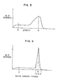
- Sampling of the neighborhood as described above has a nonzero probability of including pels containing text information. If a given document is 10% black and 90 % white, the samples in a given neighborhood will have a comparable distribution. This will introduce a statistical noise to the sample and thus to the shading correction which can be suppressed if an estimate is available of the likely range of background color variation. This estimate can be obtained from a histogram of the image such as is shown in FIG. 4. If a pel is found to have a color value outside the likely range for background, the correction value for that pel is set to zero. Thus, even for the worst possible case where all samples are outside of the permitted range of background variation, the result is equivalent to no correction being made.
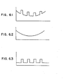
- FIG. 1.1 shows a text data character such as O being intercepted by a horizontal scan line.
- a black character on a white paper background would produce a video signal such as is shown in FIG. 1.2 having a relatively uniform flat background white level except for areas where black text data occurs at which point the video signal would switch to the black level.
- the actual video signal representative of the O of FIG. 1.1 includes shading effects which create ambiguities in separating text data from background in an image. It can be seen in FIG. 1.3, that the shading of the paper background causes a gray scale variation in areas where no text data appears which can inhibit efficient data compression and transmission and create undesired artifacts in the transmitted image.
- a video signal containing image data is stored in image buffer 12 in such a way that access may be had to an intensity value for each pel in an image.
- the data in image buffer 12 is sampled by the histogam aquisition circuit 14 to determine the gray level distribution of pels in the image.
- FIG. 3 shows such a histogram before shading correction. Note that for a black data on white background image the majority of pels are near the white intensity values since in a black on white image there are many more background pel positions than there are data pel positions.
- There are many techniques for acquiring and presenting histogram information including that shown in U. S. Patent 3,979,555 discussed above.
- Extreme white and extreme black intensity values are calculated by determination circuit 16 which also calculates a value intermediate the white and black extremes such as the median or the mean. Structure to perform this determination is in the prior art. One example of such structure is shown in U. S. Patent 3,621,129 discussed above.
- Determination circuit 16 further determines from an analysis of the majority of occurrences of pels in the histogram whether the image is black data on white background or white data on a black background.
- the above-mentioned U. S. patent 3,621,129 discusses such a determination and shows apparatus for implementing such a function.
- a range of acceptable background color intensity variation is determined by calculating the difference between the median calculated above and the majority color extreme (such as white.
- FIG. 4 shows a corrected Histogram with acceptable range R of background intensity variations.
- Access is then made to look up table 18 which has as an input a multibit digital data signal representing the gray scale intensity value for one of the samples in the selected neighborhood around a current pel.
- the output from the look up table is a signal representing the difference between the input intensity value and the median previously calculated, except that if the difference value exceeds the permitted range for background as determined above the output of the look up table for that pel is set to zero representing no correction made.
- the method according to the present invention may be implemented using a Ginnell gmr-270 image processor.
- a typical gray scale signal may have eight bits representing 256 discrete gray scale levels ranging from white to black.
- the image processor is limited to a five bit wide data path for processing. Therefore, the eight bit gray scale signal must be mapped to a five bit wide signal for processing by the image processor.
- Table I is an example of a look up table for this.
- Each block of four hexadecimal elements as shown consists of two sub-blocks each of two elements, so that in all there are 256 sub-blocks.
- Each sub-block is addressed by a respective eight bit input, and represents five output bits, in that the first element, 0 or 1 represents the first bit, and the next hexadecimal element represents the remaining four bits in binary code e.g. "lf" represents the five bit output "11111".
- Table II shows the look up table transfer function for selecting a maximum white intensity value from two inputs each of which have been mapped to five bit wide signals. Since the method set forth with respect to the first embodiment above determines an average of background from a group of samples around the current pel, if samples are taken in an all- black area such as off the edge of the frame, a skewed average will result causing an erroneous correction. Therefore, for pels in the band around the perimeter of the image, the average is taken including samples at the opposite edge of the image as if the image had been wrapped around so that the corresponding opposite edges were adjacent. Although this technique is an improvement over the prior art, there is still room for improvement since shading for example at the right and left edges of an image may not be the same due to external conditions.
- Table III is a transfer function showing the seven bit correction value for five bit shading correction input. Table III, like Table I is required only because of the signal path limitations of the particular image processor being used.
- FIG. 5 a second embodiment of the present invention will be described.
- the step of sampling pels around the current pel becomes an adaptive process whereby a fixed number of neighborhood pels are samples with the current pel and the maximum white intensity value from the group is stored. A block of these groups are then compared for the maximum white in a larger area and if the maximum light intensity value of the larger sampled area exceeds the intensity value stored for the smaller groups, the greater maximum white intensity value is stored in . place of the smaller value.
- the maximum white intensity value from the block sample as described above is not within the range of acceptable background (white) values indicating that the maximum white intensity value stored is in the gray region, a bit is set in an overlay plane in the image processor causing the sampling process to be repeated iteratively on larger blocks of pels until a maximum white intensity value is achieved which falls within the acceptable range R as shown in FIG. 4.or a predetermined number of iterations have been performed.
- Table IV shows the transfer function for a look up table for the maximum white intensity value selection in a black-on-white image. Note that the first several bits of data have the most significant bit set indicating that the maximum intensity value sample was not within the acceptable range.
- a bit is set in the overlay plane when maximum intensity value sampled is not within the acceptable range. This bit causes the sampled area to be expanded and a new set of samples taken. If an acceptable Max value is obtained, the bit is cleared and a correction value may be obtained. If acceptable Max value is not obtained, the process is iteratively repeated until a predetermined limit of iterations is achieved or an acceptable Max value is found.
- the correction value may then be obtained through a table look up employing the transfer function of Table II described above with respect to the first embodiment of the present invention.
- a second filtering is achieved by taking an average of the four nearest neighbor intensity values to the current pel. This average is locked out at the edges of the image in accordance with the overlay control described above.
- a mask is set in two separate overlay planes wherein the mask applies to the entire image if set on and to the band of pels around the perimeter of the image if set off.
- the first overlay plane is set on causing the processor to sum samples and average the summed samples in the neighborhood of the current pel to achieve a correction value.
- the first overlay plane is set off thus inhibiting the summing of neighborhood samples.
- the second overlay plane controls look up table operation. If the second overlay plane is on the current pel is multiplied by a constant through a look up table such as is shown in Table V below. This technique greatly reduces the edge effects on the shading correction.
- the nonlinear shading filter described above provides a variable pass band filtering by enabling lower pass band whenever the correction derived from earlier operation indicates a failure of the correction together with noise averaging as a final step with lock out of the averaging at the borders of the image.
Abstract
Description
- The present invention relates to image data enhancement apparatus and methods, and more particularly to apparatus and methods of filtering undesired shading effects from video images.
- In the prior art there are many image data processing systems available. The following are systems representative of the prior art.
- U. S. Patent 3,621,129 relates to devices for enhancing images by quantizing picture element levels into binary digital signals employing a threshold which is derived from the gray scale values of the image under analysis. The apparatus of the patent examines gray scale values of picture elements immediately preceeding and succeeding a feature under analysis and a variable threshold is generated which is derived from a mean value between the maximum white signal level and the maximum black signal level immediately before and after the feature under analysis. The patent does not acquire a histogram of distribution of gray scale intensity levels in the entire image to provide a uniform correction but rather provides only a localized threshold calculation.
- U. S. Patent 3,979,555 relates to a histogram equalization system that adaptively redistributes the intensity levels of video signals in order to provide an equal number of elements at all display intensity levels.
- The patent does not relate generally to a method of correcting_shading effects video images where a correction value is calculated from the variations in background level in the entire image.
- U. S. Patent 3,800,078 teaches a digitally compensated scanning system wherein an initial scan of black or background information is stored in a look-up table and compared to desired data signals to eliminate undesired variations or noise resulting from photodiode leakage current or other noise sources.
- The patent does not show a method of correcting shading effects in video images in which a histogram of distribution of gray scale intensity levels is acquired and used to calculate a threshold value and a range of permissable background gray scale variations which generates a correction signal which when combined with the raw data provides an output signal which is corrected for undesired shading effects.
- U. S. Patent 4,232,400 shows an echo control system for an adaptive echo canceller which cancels an echo signal while successively estimating the transmission characteristic of an echo path which includes means for filtering by convolution a transmitted signal including echo characteristics.
- The patent does not teach a method of correcting shading effects in video images using a histogram of distribution of gray scale intensity levels for calculating maximum white, maximum black and threshold values and generating a correction signal to eliminate shading effects.
- An article entitled "Digital Processing Techniques for Encoding of Graphics" which appeared in the Proceedings of the IEEE, Vol. 68, No. 7, July 1980 at page 757 and following provides a survey of techniques for preprocessing input documents having noise contents which create poor data compression ratios.
- The article discusses a piece wise local approach to shading correction in which a number of small overlapping samples or windows are examined and a threshold is established for each of these windows. The approach presents a potential problem with respect to different thresholds at either side of a boundary between adjacent windows. Discontinuities in the threshold going from window to window may result in undesired effects in the image. The article does not present a global shading correction algorithm in which the shading for the entire image is corrected without discontinuity.
- The prior art discussed above does not teach nor suggest the present invention as disclosed and claimed herein.
- Therefore, it is an object of the present invention to correct shading effects in video images having a plurality of picture elements where each picture element is represented by a gray scale intensity value by a method including the steps of generating a histogram of distribution of gray scale intensity values of picture elements in the image, calculating a maximum white gray scale value, a maximum black gray scale value and an intermediate gray scale value from the histogram, determining the image polarity from the intermediate value and the extreme gray scale values, determining a range of permitted background gray scale intensity values, sampling gray scale intensity values in a predetermined region around a pel whose gray scale value is to be corrected for shading, calculating a correction value for the current picture element by comparing the current picture element gray scale value with the range of background gray scale variations, setting the correction value to a predetermined constant if the current picture element gray scale intensity value is outside the range of background gray scale variations, correcting the current picture element of gray scale intensity value by subtracting the correction value from the current picture element gray scale value to achieve a shading corrected value for the current picture element and executing the above steps on each picture element in the image to correct for undesired shading effects throughout the image.
- It is another object of the present invention to correct shading effects in video images as above by a method further including the step of repeating the sampling over an expanded region if the maximum color gray scale value representing data is less than a predetermined value.
- It is yet another object of the present invention to correct shading effects in video images as above wherein an average value is calculated for background pels in a region around the current pel to provide a basis for calculating a correction value.
- Accordingly, a method of correcting shading effects in video images according to the present invention employs an image processing system including a plurality of full image buffers, means for providing a histogram calculation for the image to be corrected and means for controlling the operation of the image processor including the steps of generating and storing a histogram of distribution of gray scale intensity values for all picture elements in the image; calculating from the histogram an extreme white and extreme black gray scale value and an intermediate value for the image; determining image polarity from the intermediate value and its relationship to the extreme white and extreme black gray scale values; determining a range of permitted background grayscale intensity of variations from the steps of calculating and determining; sampling gray scale intensity value of picture elements in a region around a current picture element to be corrected; calculating a correction value for the current picture element from the background gray scale value determined from the previous step; executing the above steps for each picture element in the image to provide a uniform shading correction throughout a video image.
- The foregoing and other objects, features and advantages of the invention will be apparent from the more particular description of the preferred embodiments of the invention, as illustrated in the accompanying drawing.
-
- FIG. 1.1 shows a character of a video image intercepted by a scan line to produce a video signal.
- FIG. 1.2 shows an idealized video signal generated from the -character of FIG. 1.1.
- FIG. 1.3 shows a video signal which includes shading defects from camera characteristics, lighting or the like.
- FIG. 2 is a block diagram of apparatus according to the present invention for correcting shading defects in a video image.
- FIG. 3 is a diagram showing a histogram of the number of occurrences of pel intensity values before shading correction.
- FIG. 4 is a histogram after shading correction has been performed in accordance with the apparatus and method of the present invention.
- FIG. 5 is a flowchart of the method for performing shading corrections on digital video images in accordance with a second embodiment of the present invention.
- FIG. 6.1 is a diagram showing an uncorrected video signal having a concave shading defect. FIG. 6.2 is a diagram showing the concave shading defect removed from the video signal.
- FIG. 6.3 is a diagram showing the shading corrected video signal in accordance with the present invention.
- Most images captured from television cameras have substantial shading problems, even when the cameras incorporate shading correction circuitry. The shading, or low spacial frequency variations, in the image can cause problems when the image is to be converted by thresholding to a graphics image having one or two bits per pel'(picture element).
- Apparatus and method is shown for correction of the shading effects. The method according to the invention may be implemented by a commercially available image processor such as a Ginnell gmr-270 operating under the control of a digital data processing system such as the IBM Series I. The shading correction method and apparatus according to the present invention is based upon the following concept. Gray scale values in a general neighborhood around a given pel are sampled. The samples must be far enough from the pel being corrected and from each other that any data related information content shows essentially no correlation between samples or with the pel being corrected. The samples should be closely enough spaced, however, that an accurate estimate of the low spacial frequency shading effects can be obtained. As a practical matter, samples should be taken at a radius distance from the current pel greater than the character size of the text data and perhaps in the range of 10 to 20 pel distances from the current pel. In one embodiment, the neighborhood samples may be taken in a generally circular pattern around the current pel.
- Sampling of the neighborhood as described above has a nonzero probability of including pels containing text information. If a given document is 10% black and 90% white, the samples in a given neighborhood will have a comparable distribution. This will introduce a statistical noise to the sample and thus to the shading correction which can be suppressed if an estimate is available of the likely range of background color variation. This estimate can be obtained from a histogram of the image such as is shown in FIG. 4. If a pel is found to have a color value outside the likely range for background, the correction value for that pel is set to zero. Thus, even for the worst possible case where all samples are outside of the permitted range of background variation, the result is equivalent to no correction being made.
- Referring now to FIGS. 1.1, 1.2 and 1.3, the generation of a video signal with shading effects will be discussed. FIG. 1.1 shows a text data character such as O being intercepted by a horizontal scan line.
- Ideally, a black character on a white paper background would produce a video signal such as is shown in FIG. 1.2 having a relatively uniform flat background white level except for areas where black text data occurs at which point the video signal would switch to the black level.
- As can be seen in FIG. 1.3, the actual video signal representative of the O of FIG. 1.1 includes shading effects which create ambiguities in separating text data from background in an image. It can be seen in FIG. 1.3, that the shading of the paper background causes a gray scale variation in areas where no text data appears which can inhibit efficient data compression and transmission and create undesired artifacts in the transmitted image.
- Referring now to FIG. 2, apparatus according to the present invention will be described. A video signal containing image data is stored in
image buffer 12 in such a way that access may be had to an intensity value for each pel in an image. The data inimage buffer 12 is sampled by the histogam aquisition circuit 14 to determine the gray level distribution of pels in the image. FIG. 3 shows such a histogram before shading correction. Note that for a black data on white background image the majority of pels are near the white intensity values since in a black on white image there are many more background pel positions than there are data pel positions. There are many techniques for acquiring and presenting histogram information including that shown in U. S. Patent 3,979,555 discussed above. - Extreme white and extreme black intensity values are calculated by
determination circuit 16 which also calculates a value intermediate the white and black extremes such as the median or the mean. Structure to perform this determination is in the prior art. One example of such structure is shown in U. S. Patent 3,621,129 discussed above. -
Determination circuit 16 further determines from an analysis of the majority of occurrences of pels in the histogram whether the image is black data on white background or white data on a black background. The above-mentioned U. S. patent 3,621,129 discusses such a determination and shows apparatus for implementing such a function. - A range of acceptable background color intensity variation is determined by calculating the difference between the median calculated above and the majority color extreme (such as white. FIG. 4 shows a corrected Histogram with acceptable range R of background intensity variations. Access is then made to look up table 18 which has as an input a multibit digital data signal representing the gray scale intensity value for one of the samples in the selected neighborhood around a current pel. The output from the look up table is a signal representing the difference between the input intensity value and the median previously calculated, except that if the difference value exceeds the permitted range for background as determined above the output of the look up table for that pel is set to zero representing no correction made. In a first embodiment of the invention, further samples are taken in the selected neighborhood point by point around the current pel to be corrected and the correction terms generated by the look up table are summed. An average value is obtained by dividing the sum of correction terms by the number of samples taken. This averaged correction value is used to correct the current pel intensity value for shading effects in
shading correction filter 20. The shading corrected intensity value of the current pel is determined by the following equation°
- X is the original value of the current pel.
- M is the median value and
- A is the average value of the neighborhood
- background determined above. As was discussed above, the method according to the present invention may be implemented using a Ginnell gmr-270 image processor. However, a typical gray scale signal may have eight bits representing 256 discrete gray scale levels ranging from white to black. The image processor is limited to a five bit wide data path for processing. Therefore, the eight bit gray scale signal must be mapped to a five bit wide signal for processing by the image processor.
- Table I is an example of a look up table for this. Each block of four hexadecimal elements as shown consists of two sub-blocks each of two elements, so that in all there are 256 sub-blocks. Each sub-block is addressed by a respective eight bit input, and represents five output bits, in that the first element, 0 or 1 represents the first bit, and the next hexadecimal element represents the remaining four bits in binary code e.g. "lf" represents the five bit output "11111".
- Table II shows the look up table transfer function for selecting a maximum white intensity value from two inputs each of which have been mapped to five bit wide signals.


- Referring now to FIG. 5, a second embodiment of the present invention will be described.
- The steps of generating a histogram, calculating extreme white and black values in the image, calculating a median gray scale value and testing for image polarity are common with the first embodiment described above and each of the steps individually is very straightforward.
- In the second embodiment, the step of sampling pels around the current pel becomes an adaptive process whereby a fixed number of neighborhood pels are samples with the current pel and the maximum white intensity value from the group is stored. A block of these groups are then compared for the maximum white in a larger area and if the maximum light intensity value of the larger sampled area exceeds the intensity value stored for the smaller groups, the greater maximum white intensity value is stored in . place of the smaller value.

- If the maximum white intensity value from the block sample as described above is not within the range of acceptable background (white) values indicating that the maximum white intensity value stored is in the gray region, a bit is set in an overlay plane in the image processor causing the sampling process to be repeated iteratively on larger blocks of pels until a maximum white intensity value is achieved which falls within the acceptable range R as shown in FIG. 4.or a predetermined number of iterations have been performed.
- Table IV shows the transfer function for a look up table for the maximum white intensity value selection in a black-on-white image. Note that the first several bits of data have the most significant bit set indicating that the maximum intensity value sample was not within the acceptable range.
- A bit is set in the overlay plane when maximum intensity value sampled is not within the acceptable range. This bit causes the sampled area to be expanded and a new set of samples taken. If an acceptable Max value is obtained, the bit is cleared and a correction value may be obtained. If acceptable Max value is not obtained, the process is iteratively repeated until a predetermined limit of iterations is achieved or an acceptable Max value is found.
- The correction value may then be obtained through a table look up employing the transfer function of Table II described above with respect to the first embodiment of the present invention. A second filtering is achieved by taking an average of the four nearest neighbor intensity values to the current pel. This average is locked out at the edges of the image in accordance with the overlay control described above.

- For pels in the edge band around the perimeter image, the first overlay plane is set off thus inhibiting the summing of neighborhood samples.
- The second overlay plane controls look up table operation. If the second overlay plane is on the current pel is multiplied by a constant through a look up table such as is shown in Table V below. This technique greatly reduces the edge effects on the shading correction.
- The nonlinear shading filter described above provides a variable pass band filtering by enabling lower pass band whenever the correction derived from earlier operation indicates a failure of the correction together with noise averaging as a final step with lock out of the averaging at the borders of the image.

Claims (6)
Applications Claiming Priority (2)
| Application Number | Priority Date | Filing Date | Title |
|---|---|---|---|
| US45490982A | 1982-12-30 | 1982-12-30 | |
| US454909 | 1999-12-03 |
Publications (3)
| Publication Number | Publication Date |
|---|---|
| EP0113016A2 true EP0113016A2 (en) | 1984-07-11 |
| EP0113016A3 EP0113016A3 (en) | 1987-04-29 |
| EP0113016B1 EP0113016B1 (en) | 1990-09-05 |
Family
ID=23806568
Family Applications (1)
| Application Number | Title | Priority Date | Filing Date |
|---|---|---|---|
| EP83111645A Expired EP0113016B1 (en) | 1982-12-30 | 1983-11-22 | Correction of shading effects in video images |
Country Status (4)
| Country | Link |
|---|---|
| US (1) | US4695884A (en) |
| EP (1) | EP0113016B1 (en) |
| JP (1) | JPS59125176A (en) |
| DE (1) | DE3381868D1 (en) |
Cited By (13)
| Publication number | Priority date | Publication date | Assignee | Title |
|---|---|---|---|---|
| EP0187911A2 (en) * | 1985-01-15 | 1986-07-23 | International Business Machines Corporation | Method and apparatus for thresholding image data |
| DE3629409A1 (en) * | 1986-08-29 | 1988-03-03 | Agfa Gevaert Ag | METHOD FOR CONTRAST EVALUATION IN ELECTRONIC IMAGE PROCESSING |
| DE3629422A1 (en) * | 1986-08-29 | 1988-03-03 | Agfa Gevaert Ag | METHOD AND DEVICE FOR ADJUSTING EXPOSURE SIZES ON A COPIER |
| US4799106A (en) * | 1985-08-22 | 1989-01-17 | Rank Pullin Controls Limited | Controlling image signals in an imaging apparatus |
| US4833545A (en) * | 1986-08-15 | 1989-05-23 | Kabushiki Kaisha Kenwood | Receiver system of image signal from weather satellite |
| US4903145A (en) * | 1986-08-06 | 1990-02-20 | Canon Kabushiki Kaisha | Image quality control apparatus capable of density-correcting plural areas of different types |
| WO1991008640A1 (en) * | 1989-11-30 | 1991-06-13 | Eastman Kodak Company | Copier and process for copying |
| US5032929A (en) * | 1988-04-25 | 1991-07-16 | Fujitsu Limited | Document reading device |
| US5086486A (en) * | 1984-09-19 | 1992-02-04 | Canon Kabushiki Kaisha | Apparatus for reading a document and processing the image |
| US5228099A (en) * | 1984-09-19 | 1993-07-13 | Canon Kabushiki Kaisha | Apparatus for reading a document and processing the image |
| EP0578875A1 (en) * | 1992-07-17 | 1994-01-19 | Recognition International Inc. | Normalizing correlator for video processing |
| EP0803842A2 (en) * | 1996-03-26 | 1997-10-29 | Sharp Kabushiki Kaisha | Binary image forming device |
| US6972286B2 (en) | 2000-11-17 | 2005-12-06 | Pharmacia And Upjohn Company | Oxazolidinones having a benzannulated 6- or 7-membered heterocycle |
Families Citing this family (71)
| Publication number | Priority date | Publication date | Assignee | Title |
|---|---|---|---|---|
| DE3408107C2 (en) * | 1983-03-06 | 1996-05-30 | Canon Kk | Halftone color image recorder |
| US5144687A (en) * | 1985-03-02 | 1992-09-01 | Kabushika Kaisha Toshiba | Image processing apparatus including spatial shift variant filter |
| US5065257A (en) * | 1985-03-20 | 1991-11-12 | Canon Kabushiki Kaisha | Image processing apparatus with means for compensating for dust., etc., on an original |
| US4817166A (en) * | 1986-05-05 | 1989-03-28 | Perceptics Corporation | Apparatus for reading a license plate |
| US4847786A (en) * | 1986-08-20 | 1989-07-11 | The Regents Of The University Of California | Object analysis of multi-valued images |
| US4982342A (en) * | 1987-11-05 | 1991-01-01 | Kabushiki Kaisha Toyota Chuo Kenkyusho | Image processor system having multifunction look-up table units |
| US5065444A (en) * | 1988-02-08 | 1991-11-12 | Northrop Corporation | Streak removal filtering method and apparatus |
| JP2709356B2 (en) * | 1988-05-16 | 1998-02-04 | 株式会社鷹山 | Image processing method |
| US5191444A (en) * | 1988-06-20 | 1993-03-02 | Sanyo Electric Co., Ltd. | Method of converting gradation of a digital image and a circuit thereof and a print density controlling apparatus for a printer and a printer using this method |
| DE3835981A1 (en) * | 1988-10-21 | 1990-04-26 | Mtu Muenchen Gmbh | METHOD FOR TESTING THE TOLERANCES OF HOLES |
| US5063607A (en) * | 1988-10-24 | 1991-11-05 | Hughes Aircraft Company | Image contrast enhancement technique |
| US5081685A (en) * | 1988-11-29 | 1992-01-14 | Westinghouse Electric Corp. | Apparatus and method for reading a license plate |
| US4937682A (en) * | 1988-12-28 | 1990-06-26 | Hewlett-Packard Company | Method and apparatus for providing contrast/intensity control in a document scanner |
| US5185602A (en) * | 1989-04-10 | 1993-02-09 | Cirrus Logic, Inc. | Method and apparatus for producing perception of high quality grayscale shading on digitally commanded displays |
| US4970598A (en) * | 1989-05-30 | 1990-11-13 | Eastman Kodak Company | Method for correcting shading effects in video images |
| US5107422A (en) * | 1989-10-02 | 1992-04-21 | Kamentsky Louis A | Method and apparatus for measuring multiple optical properties of biological specimens |
| JPH03155267A (en) * | 1989-11-14 | 1991-07-03 | Fuji Photo Film Co Ltd | Nonuniform sensitivity correcting method for picture reader |
| JPH041866A (en) * | 1990-04-18 | 1992-01-07 | Toyobo Co Ltd | Method and device for image processing |
| CA2040672C (en) * | 1990-04-26 | 1995-05-30 | Masaaki Kanashiki | Image signal processing apparatus |
| US6009193A (en) * | 1990-05-16 | 1999-12-28 | Canon Kabushiki Kaisha | Method and apparatus for converting N-value image to M-value image, for < NM |
| US5091971A (en) * | 1990-09-28 | 1992-02-25 | Xerox Corporation | Method and apparatus for high-speed electronic data signal modification and improvement |
| US5133022A (en) * | 1991-02-06 | 1992-07-21 | Recognition Equipment Incorporated | Normalizing correlator for video processing |
| US5157497A (en) * | 1991-02-25 | 1992-10-20 | Matsushita Electric Industrial Co., Ltd. | Method and apparatus for detecting and compensating for white shading errors in a digitized video signal |
| US5459797A (en) * | 1991-03-30 | 1995-10-17 | Kabushiki Kaisha Toshiba | Character reading system |
| US5289282A (en) * | 1991-05-28 | 1994-02-22 | Matsushita Electric Industrial Co., Ltd. | Video signal gradation corrector |
| JP2936791B2 (en) * | 1991-05-28 | 1999-08-23 | 松下電器産業株式会社 | Gradation correction device |
| JP3019479B2 (en) * | 1991-06-28 | 2000-03-13 | 松下電器産業株式会社 | Gradation correction device |
| US5249241A (en) * | 1991-07-09 | 1993-09-28 | The United States Of America As Represented By The Secretary Of The Air Force | Real-time automated scene display for infrared cameras |
| US5548661A (en) * | 1991-07-12 | 1996-08-20 | Price; Jeffrey H. | Operator independent image cytometer |
| DE69229085T2 (en) * | 1991-07-12 | 1999-11-18 | Educational Testing Service Pr | Image processing system |
| EP0541870B1 (en) * | 1991-11-14 | 1996-05-15 | International Business Machines Corporation | Image processing apparatus with improved data conversion testing |
| US5751265A (en) * | 1991-12-24 | 1998-05-12 | Cirrus Logic, Inc. | Apparatus and method for producing shaded images on display screens |
| WO1993013513A1 (en) * | 1991-12-24 | 1993-07-08 | Cirrus Logic, Inc. | Process for producing shaded images on display screens |
| US5485281A (en) * | 1992-07-31 | 1996-01-16 | E. I. Du Pont De Nemours And Company | Raster image processing with pixel mapping to allow image border density allocation |
| US5416857A (en) * | 1992-10-21 | 1995-05-16 | International Business Machines Corporation | Apparatus and method for compressing data while retaining image integrity |
| US5473737A (en) * | 1993-10-12 | 1995-12-05 | International Business Machines Corporation | Method and apparatus for displaying a composite image made up of a foreground image and a background image |
| EP0677818B1 (en) * | 1994-04-15 | 2000-05-10 | Canon Kabushiki Kaisha | Image pre-processor for character recognition system |
| US5467408A (en) * | 1994-04-22 | 1995-11-14 | The Gillette Company | Ball point writing quality analysis |
| US5519787A (en) * | 1994-07-25 | 1996-05-21 | Canon Kabushiki Kaisha | Method of compressing image data having a uniform background tint |
| US6069645A (en) * | 1994-10-31 | 2000-05-30 | Hewlett-Packard Company | Method and apparatus for controlling dot size in image forming apparatus having an array of lasers |
| US5534945A (en) * | 1994-12-16 | 1996-07-09 | International Business Machines Corporation | System and method for providing black diffusion in video image processing |
| DE69526635T2 (en) * | 1994-12-29 | 2002-12-05 | Koninkl Philips Electronics Nv | Imaging device and method for improving geometric optical image distortions |
| KR100203239B1 (en) * | 1995-02-16 | 1999-06-15 | 윤종용 | Method and apparatus for white shading compensation |
| EP0744862B1 (en) * | 1995-05-24 | 1999-11-17 | Océ-Technologies B.V. | A method of and apparatus for correcting the output signals of a plurality of photodetecting elements |
| US5754309A (en) * | 1995-06-06 | 1998-05-19 | Apple Computer, Inc. | Tone correction for multi-level halftoned images |
| JPH09229642A (en) * | 1996-02-27 | 1997-09-05 | Matsushita Electric Ind Co Ltd | Method for inspecting appearance of electronic part |
| JP3862789B2 (en) * | 1996-09-30 | 2006-12-27 | 株式会社東芝 | Image processing apparatus, image processing method, and image forming apparatus |
| US6192163B1 (en) * | 1996-10-29 | 2001-02-20 | Seiko Epson Corporation | Image processing method and image processing apparatus |
| US6211859B1 (en) | 1997-03-10 | 2001-04-03 | Chips & Technologies, Llc | Method for reducing pulsing on liquid crystal displays |
| US6034663A (en) * | 1997-03-10 | 2000-03-07 | Chips & Technologies, Llc | Method for providing grey scale images to the visible limit on liquid crystal displays |
| US6175660B1 (en) * | 1997-03-25 | 2001-01-16 | Minolta Co., Ltd. | Image reading apparatus |
| US6252578B1 (en) | 1997-10-07 | 2001-06-26 | Intel Corporation | Method for reducing flicker when displaying processed digital data on video displays having a low refresh rate |
| US6038347A (en) * | 1997-11-03 | 2000-03-14 | Victor Company Of Japan, Ltd. | Method and apparatus for compressing picture-representing data |
| US6144774A (en) * | 1997-11-03 | 2000-11-07 | Victor Company Of Japan, Ltd. | Method and apparatus for compressing picture-representing data |
| US6043900A (en) * | 1998-03-31 | 2000-03-28 | Xerox Corporation | Method and system for automatically detecting a background type of a scanned document utilizing a leadedge histogram thereof |
| US6285798B1 (en) * | 1998-07-06 | 2001-09-04 | Eastman Kodak Company | Automatic tone adjustment by contrast gain-control on edges |
| JP2001126075A (en) * | 1999-08-17 | 2001-05-11 | Fuji Photo Film Co Ltd | Method and device for picture processing, and recording medium |
| US6633687B1 (en) | 1999-09-10 | 2003-10-14 | Intel Corporation | Method and apparatus for image contrast modulation |
| SG103253A1 (en) | 2000-01-26 | 2004-04-29 | Kent Ridge Digital Labs | Method and apparatus for cancelling lighting variations in object recognition |
| EP1231564B1 (en) * | 2001-02-09 | 2007-03-28 | Imaging Solutions AG | Digital local control of image properties by means of masks |
| EP1231566B1 (en) * | 2001-02-09 | 2006-08-02 | Imaging Solutions AG | Digital local control of image properties by means of masks |
| JP2005151282A (en) * | 2003-11-18 | 2005-06-09 | Fuji Xerox Co Ltd | Apparatus and method of image processing, and program |
| JP2005301095A (en) * | 2004-04-15 | 2005-10-27 | Semiconductor Energy Lab Co Ltd | Display device |
| JP2007028362A (en) * | 2005-07-20 | 2007-02-01 | Seiko Epson Corp | Apparatus and method for processing image data with mixed background image and target image |
| US8503815B2 (en) * | 2007-05-23 | 2013-08-06 | CSR Technology, Inc. | Highlight recovery using digital lighting module |
| TWI401973B (en) * | 2009-02-13 | 2013-07-11 | Altek Corp | A Method to Improve the Color Shadow in Digital Image |
| US8571307B2 (en) | 2010-11-16 | 2013-10-29 | Hand Held Products, Inc. | Method and system operative to process monochrome image data |
| US8600158B2 (en) | 2010-11-16 | 2013-12-03 | Hand Held Products, Inc. | Method and system operative to process color image data |
| EP2732618B1 (en) * | 2011-08-12 | 2016-10-12 | Fraunhofer-Gesellschaft zur Förderung der angewandten Forschung e.V. | Camera arrangement for image detection, x-ray system and method for balancing and operating |
| JP6171727B2 (en) * | 2013-08-23 | 2017-08-02 | ブラザー工業株式会社 | Image processing device, sheet, computer program |
| KR102643588B1 (en) * | 2019-01-21 | 2024-03-04 | 엘지전자 주식회사 | Camera device, and electronic apparatus including the same |
Citations (4)
| Publication number | Priority date | Publication date | Assignee | Title |
|---|---|---|---|---|
| US3621129A (en) * | 1968-05-01 | 1971-11-16 | Metals Research Ltd | Detection devices for image analysis systems |
| US3979555A (en) * | 1975-05-27 | 1976-09-07 | Hughes Aircraft Company | Histogram equalization system for display improvement |
| JPS56119575A (en) * | 1980-02-26 | 1981-09-19 | Hitachi Ltd | Binary system of video signal |
| JPS57147375A (en) * | 1981-03-05 | 1982-09-11 | Nec Corp | Adaptive quantizing circuit |
Family Cites Families (6)
| Publication number | Priority date | Publication date | Assignee | Title |
|---|---|---|---|---|
| US3800078A (en) * | 1972-12-18 | 1974-03-26 | Ibm | Digitally compensated scanning system |
| JPS5829012B2 (en) * | 1978-05-16 | 1983-06-20 | ケイディディ株式会社 | Echo control method |
| DE3107521A1 (en) * | 1981-02-27 | 1982-09-16 | Siemens AG, 1000 Berlin und 8000 München | METHOD FOR AUTOMATICALLY DETECTING IMAGE AND TEXT OR GRAPHIC AREAS ON PRINT ORIGINALS |
| GB2115256B (en) * | 1981-12-19 | 1986-01-29 | Konishiroku Photo Ind | Picture image discriminating apparatus |
| US4493106A (en) * | 1981-12-24 | 1985-01-08 | International Computers Limited | Image digitizing systems |
| US4504864A (en) * | 1982-12-30 | 1985-03-12 | International Business Machines Corporation | Nonlinear filtering of gray scale images |
-
1983
- 1983-09-19 JP JP58171444A patent/JPS59125176A/en active Granted
- 1983-11-22 DE DE8383111645T patent/DE3381868D1/en not_active Expired - Fee Related
- 1983-11-22 EP EP83111645A patent/EP0113016B1/en not_active Expired
-
1985
- 1985-02-01 US US06/697,300 patent/US4695884A/en not_active Expired - Fee Related
Patent Citations (4)
| Publication number | Priority date | Publication date | Assignee | Title |
|---|---|---|---|---|
| US3621129A (en) * | 1968-05-01 | 1971-11-16 | Metals Research Ltd | Detection devices for image analysis systems |
| US3979555A (en) * | 1975-05-27 | 1976-09-07 | Hughes Aircraft Company | Histogram equalization system for display improvement |
| JPS56119575A (en) * | 1980-02-26 | 1981-09-19 | Hitachi Ltd | Binary system of video signal |
| JPS57147375A (en) * | 1981-03-05 | 1982-09-11 | Nec Corp | Adaptive quantizing circuit |
Non-Patent Citations (2)
| Title |
|---|
| PATENTS ABSTRACTS OF JAPAN, vol. 5, no. 197 (E-86)[869], 15th December 1981; & JP-A-56 119 575 (HITACHI SEISAKUSHO K.K.) 19-09-1981 * |
| PATENTS ABSTRACTS OF JAPAN, vol. 6, no. 247 (E-146)[1125], 7th December 1982; & JP-A-57 147 375 (NIPPON DENKI K.K.) 11-09-1982 * |
Cited By (16)
| Publication number | Priority date | Publication date | Assignee | Title |
|---|---|---|---|---|
| US5086486A (en) * | 1984-09-19 | 1992-02-04 | Canon Kabushiki Kaisha | Apparatus for reading a document and processing the image |
| US5228099A (en) * | 1984-09-19 | 1993-07-13 | Canon Kabushiki Kaisha | Apparatus for reading a document and processing the image |
| EP0187911A3 (en) * | 1985-01-15 | 1987-06-16 | International Business Machines Corporation | Method and apparatus for thresholding image data |
| EP0187911A2 (en) * | 1985-01-15 | 1986-07-23 | International Business Machines Corporation | Method and apparatus for thresholding image data |
| US4799106A (en) * | 1985-08-22 | 1989-01-17 | Rank Pullin Controls Limited | Controlling image signals in an imaging apparatus |
| US4903145A (en) * | 1986-08-06 | 1990-02-20 | Canon Kabushiki Kaisha | Image quality control apparatus capable of density-correcting plural areas of different types |
| US4833545A (en) * | 1986-08-15 | 1989-05-23 | Kabushiki Kaisha Kenwood | Receiver system of image signal from weather satellite |
| DE3629409A1 (en) * | 1986-08-29 | 1988-03-03 | Agfa Gevaert Ag | METHOD FOR CONTRAST EVALUATION IN ELECTRONIC IMAGE PROCESSING |
| DE3629422A1 (en) * | 1986-08-29 | 1988-03-03 | Agfa Gevaert Ag | METHOD AND DEVICE FOR ADJUSTING EXPOSURE SIZES ON A COPIER |
| US5032929A (en) * | 1988-04-25 | 1991-07-16 | Fujitsu Limited | Document reading device |
| WO1991008640A1 (en) * | 1989-11-30 | 1991-06-13 | Eastman Kodak Company | Copier and process for copying |
| EP0578875A1 (en) * | 1992-07-17 | 1994-01-19 | Recognition International Inc. | Normalizing correlator for video processing |
| EP0803842A2 (en) * | 1996-03-26 | 1997-10-29 | Sharp Kabushiki Kaisha | Binary image forming device |
| EP0803842A3 (en) * | 1996-03-26 | 1998-07-22 | Sharp Kabushiki Kaisha | Binary image forming device |
| US5912992A (en) * | 1996-03-26 | 1999-06-15 | Sharp Kabushiki Kaisha | Binary image forming device with shading correction means using interpolation of shade densities determined by using sample points |
| US6972286B2 (en) | 2000-11-17 | 2005-12-06 | Pharmacia And Upjohn Company | Oxazolidinones having a benzannulated 6- or 7-membered heterocycle |
Also Published As
| Publication number | Publication date |
|---|---|
| JPH0432587B2 (en) | 1992-05-29 |
| EP0113016B1 (en) | 1990-09-05 |
| DE3381868D1 (en) | 1990-10-11 |
| US4695884A (en) | 1987-09-22 |
| EP0113016A3 (en) | 1987-04-29 |
| JPS59125176A (en) | 1984-07-19 |
Similar Documents
| Publication | Publication Date | Title |
|---|---|---|
| EP0113016B1 (en) | Correction of shading effects in video images | |
| JP3097785B2 (en) | Image processing device | |
| US5666443A (en) | Image processor with edge emphasis of image data | |
| EP0372950B1 (en) | Image reducing apparatus | |
| US5293430A (en) | Automatic image segmentation using local area maximum and minimum image signals | |
| US5832140A (en) | Automated quality assurance image processing system | |
| JPH04119763A (en) | Image processor | |
| EP0114961A2 (en) | Nonlinear filtering of gray scale video images | |
| JPH03131173A (en) | Picture processing system | |
| EP0506380A2 (en) | Image processing apparatus | |
| JP3031994B2 (en) | Image processing device | |
| JPH0787313A (en) | System and device for image processing | |
| JP2851724B2 (en) | Image processing device | |
| JP3336046B2 (en) | Image area separation device | |
| US6842267B1 (en) | Image processing method | |
| JPH0951431A (en) | Image processing unit | |
| JP3256267B2 (en) | Image processing device | |
| JP2702593B2 (en) | Isolated point removal device | |
| JP3032238B2 (en) | Image processing device | |
| JP2860039B2 (en) | Pseudo halftone image reduction device | |
| JPH0554190A (en) | Picture processor | |
| KR930005131B1 (en) | Histogram equalization for picture tone | |
| KR930003482B1 (en) | Simple identification method of mixed video and text documents | |
| JPH07104932B2 (en) | How to create character image data | |
| JPH05336350A (en) | Image processing method |
Legal Events
| Date | Code | Title | Description |
|---|---|---|---|
| PUAI | Public reference made under article 153(3) epc to a published international application that has entered the european phase |
Free format text: ORIGINAL CODE: 0009012 |
|
| AK | Designated contracting states |
Designated state(s): DE FR GB IT |
|
| 17P | Request for examination filed |
Effective date: 19841029 |
|
| PUAL | Search report despatched |
Free format text: ORIGINAL CODE: 0009013 |
|
| AK | Designated contracting states |
Kind code of ref document: A3 Designated state(s): DE FR GB IT |
|
| 17Q | First examination report despatched |
Effective date: 19890412 |
|
| GRAA | (expected) grant |
Free format text: ORIGINAL CODE: 0009210 |
|
| AK | Designated contracting states |
Kind code of ref document: B1 Designated state(s): DE FR GB IT |
|
| REF | Corresponds to: |
Ref document number: 3381868 Country of ref document: DE Date of ref document: 19901011 |
|
| ET | Fr: translation filed | ||
| ITF | It: translation for a ep patent filed |
Owner name: IBM - DR. ALFREDO BRAVI |
|
| ITTA | It: last paid annual fee | ||
| PLBE | No opposition filed within time limit |
Free format text: ORIGINAL CODE: 0009261 |
|
| STAA | Information on the status of an ep patent application or granted ep patent |
Free format text: STATUS: NO OPPOSITION FILED WITHIN TIME LIMIT |
|
| 26N | No opposition filed | ||
| PGFP | Annual fee paid to national office [announced via postgrant information from national office to epo] |
Ref country code: GB Payment date: 19931019 Year of fee payment: 11 |
|
| PGFP | Annual fee paid to national office [announced via postgrant information from national office to epo] |
Ref country code: FR Payment date: 19931103 Year of fee payment: 11 |
|
| PGFP | Annual fee paid to national office [announced via postgrant information from national office to epo] |
Ref country code: DE Payment date: 19931118 Year of fee payment: 11 |
|
| PG25 | Lapsed in a contracting state [announced via postgrant information from national office to epo] |
Ref country code: GB Effective date: 19941122 |
|
| GBPC | Gb: european patent ceased through non-payment of renewal fee |
Effective date: 19941122 |
|
| PG25 | Lapsed in a contracting state [announced via postgrant information from national office to epo] |
Ref country code: FR Effective date: 19950731 |
|
| PG25 | Lapsed in a contracting state [announced via postgrant information from national office to epo] |
Ref country code: DE Effective date: 19950801 |
|
| REG | Reference to a national code |
Ref country code: FR Ref legal event code: ST |