EP0113011B1 - Reject assembly for sheet material handling apparatus - Google Patents
Reject assembly for sheet material handling apparatus Download PDFInfo
- Publication number
- EP0113011B1 EP0113011B1 EP83111530A EP83111530A EP0113011B1 EP 0113011 B1 EP0113011 B1 EP 0113011B1 EP 83111530 A EP83111530 A EP 83111530A EP 83111530 A EP83111530 A EP 83111530A EP 0113011 B1 EP0113011 B1 EP 0113011B1
- Authority
- EP
- European Patent Office
- Prior art keywords
- sheets
- reject
- ramp
- group
- support surface
- Prior art date
- Legal status (The legal status is an assumption and is not a legal conclusion. Google has not performed a legal analysis and makes no representation as to the accuracy of the status listed.)
- Expired
Links
- 239000000463 material Substances 0.000 title claims description 13
- 239000007858 starting material Substances 0.000 description 9
- 238000007689 inspection Methods 0.000 description 7
- 230000002950 deficient Effects 0.000 description 5
- 238000010276 construction Methods 0.000 description 3
- 239000004020 conductor Substances 0.000 description 2
- 238000001514 detection method Methods 0.000 description 2
- 230000000694 effects Effects 0.000 description 2
- 239000002699 waste material Substances 0.000 description 2
- 230000001419 dependent effect Effects 0.000 description 1
- 230000000717 retained effect Effects 0.000 description 1
- 238000009966 trimming Methods 0.000 description 1
Images



Classifications
-
- B—PERFORMING OPERATIONS; TRANSPORTING
- B65—CONVEYING; PACKING; STORING; HANDLING THIN OR FILAMENTARY MATERIAL
- B65H—HANDLING THIN OR FILAMENTARY MATERIAL, e.g. SHEETS, WEBS, CABLES
- B65H39/00—Associating, collating, or gathering articles or webs
- B65H39/02—Associating,collating or gathering articles from several sources
- B65H39/04—Associating,collating or gathering articles from several sources from piles
- B65H39/055—Associating,collating or gathering articles from several sources from piles by collecting in juxtaposed carriers
-
- B—PERFORMING OPERATIONS; TRANSPORTING
- B65—CONVEYING; PACKING; STORING; HANDLING THIN OR FILAMENTARY MATERIAL
- B65H—HANDLING THIN OR FILAMENTARY MATERIAL, e.g. SHEETS, WEBS, CABLES
- B65H29/00—Delivering or advancing articles from machines; Advancing articles to or into piles
- B65H29/58—Article switches or diverters
- B65H29/62—Article switches or diverters diverting faulty articles from the main streams
-
- B—PERFORMING OPERATIONS; TRANSPORTING
- B65—CONVEYING; PACKING; STORING; HANDLING THIN OR FILAMENTARY MATERIAL
- B65H—HANDLING THIN OR FILAMENTARY MATERIAL, e.g. SHEETS, WEBS, CABLES
- B65H2404/00—Parts for transporting or guiding the handled material
- B65H2404/20—Belts
- B65H2404/26—Particular arrangement of belt, or belts
- B65H2404/261—Arrangement of belts, or belt(s) / roller(s) facing each other for forming a transport nip
Definitions
- the present invention relates to a collator according to the preamble of Patent Claim 1, and particularly to collators operable to stitch groups of sheets containing a selected number of sheets and to reject groups of sheets containing more or less than the selected number of sheets.
- a known collator of this type includes a plurality of hoppers which are disposed in a linear array along a main conveyor assembly.
- the main conveyor assembly sequentially moves groups of sheets received from the hoppers to a transfer station where the groups of sheets are sequentially engaged by a shuttle assembly.
- the shuttle assembly moves each group of sheets in turn to a stitching station where the group of sheets is either saddle, side or corner stiched.
- Each group of sheets is then moved from the stitching station through a folding station. After a group of sheets is folded, it moves to an upper discharge station. If a group of sheets is not to be folded, it passes to a lower discharge station.
- the machine shown in US-A-3,554,531 has been improved by using a conveyor belt assembly to move groups of sheets to and from a stitching station.
- the conveyor belt assembly has upper and lower runs which grip the groups of sheets. This structure is disclosed in GB-A-2092995.
- German Patent Publication DE-A-22 43 030 discloses a machine for preparing magazines or the like, including a reject station.
- the machine further comprises a sensing means. If it is sensed that the magazine to be prepared is not correctly set up or otherwise defective, the magazine is rejected and the further prosecution steps of the machine are inhibited in order to restart the preparation of another magazine.
- the present invention relates to a collator of the general type disclosed in U.S. Patent US-A-3,554,531 and it is an object of the invention to disclose a collator which may have a higher output and be set up with less waste material.
- the collator of the invention is characterized by the features defined in Patent Claim 1. Further characteristics are contained in the dependent Patent Claims 2 and 3.
- the collator hereinafter described in full detail includes a support surface which extends past a plurality of hoppers to a stitching station. Sheets are sequentially fed from the hoppers to form groups of sheets on the support surface. A main conveyor assembly sequentially pushes groups of sheets along the support surface to a reject station. Groups of sheets containing more or less than a predetermined number of sheets are rejected at the reject station. The groups of sheets containing the predetermined number of sheets are moved to a transfer station where they are engaged by a secondary conveyor assembly which moves them to a stitching station.
- a ramp is movable between a retracted position and an extended position.
- the reject ramp When the reject ramp is in the retracted position, it cooperates with the main support surface to support groups of sheets containing the predetermined number of sheets as they sequentially move to the stitching station.
- the ramp When the ramp is in the extended position, it projects upwardly from the main support surface to a reject conveyor.
- the main conveyor assembly pushes groups of sheets containing more or less than the predetermined number of sheets up the reject ramp to the reject conveyor.
- the groups of sheets may be intentionally moved up the reject ramp, rather than transverse through the entire machine.
- the sheets in the groups may not be damaged and may be reused.
- the control is also constructed so that the collator may operate and no material be rejected. This mode of operation is used when adjustments are being made to the folder section and the stitcher section of the machine.
- the apparatus 10 includes a supply means for supplying sheets of material.
- the supply means comprises a plurality of sheet material supply hoppers 14.
- the hoppers 14 are disposed in a linear array along a support means which is a surface 16 which slopes downwardly away from the hoppers to a guide rail 18.
- a sheet feed mechanism 20 is provided to feed sheets from each of the hoppers 14 onto the support surface 16.
- a main conveyor assembly 24 is provided to sequentially move the groups of sheets 12 along the support surface 16 past each of the hoppers 14.
- the main conveyor assembly 24 includes a plurality of pusher fingers 26 which project upwardly from the support surface 16 and engage the trailing edges of each of the groups of sheets 12 to push them along the support surface 16 (see Figs. 2 and 3).
- the pusher fingers 26 are connected with a continuous chain 30 (Fig. 5) having an upper run which extends past each of the hoppers 14 to a transfer station 32 (see Fig. 3) where the sheets are transferred from the main conveyor 24 to a secondary conveyor 36.
- the secondary conveyor assembly 36 includes upper and lower belts 40 and 42 (Figs. 3 and 5) which engage the leading edge portion of a group of sheets at the transfer station 32 and accelerate the groups of sheets away from a pusher finger 26 to a stitching station 44.
- the group of sheets is clamped between the upper and lower belts 40 and 42 of the secondary conveyor 36 to hold the-sheets against movement relative to each other.
- the upper belt 40 is moved upwardly away from the lower belt 42 to release the sheets.
- a register finger (not shown) then engages the trailing edge portions of the released sheets to register the sheets rotative to the stitching apparatus 48.
- the sheets are then stitched and again clamped by the belts 40 and 42.
- the belts 40 and 42 move the sheets to a folding station 52 (Fig. 5).
- the manner in which each group of sheets is clamped by the belts 40 and 42 and then released and registered at the stitching station 44 is the same as disclosed in GB-A-2092992.
- the groups of sheets are either saddle, side or corner stitched. If a group of sheets is corner or side stitched, the group of sheets moves through the folding station 52 to a lower discharge conveyor assembly 56 (Fig. 5) without being folded. However, if a group of sheets is saddle stitched at the stitching station 44, the group of sheets is folded by a buckle folder assembly 60 and trimmed by a knife 62 at the folding station 52 and then moved to an upper discharge conveyor assembly 64.
- the general construction and mode of operation of the buckle folder 60 and trimming knife 62 is the same as is disclosed in U.S. Patent Nos. 3,554,531 and 3,627,305.
- a reject assembly 70 is provided at a - reject station 72 (see Figs. 2, 3 and 5) located between the hoppers 14 and stitching station 44.
- the reject assembly 70 receives groups of sheets containing more or less than a predetermined number of sheets so that these incorrectly formed groups of sheets do not pass through the stitcher assembly 48 and folder 60.
- the reject assembly 70 By using the reject assembly 70 to receive groups of sheets having either more or less than a predetermined number of sheets, it is not necessary to stop operation of the sheet material handling apparatus 10 and remove the incorrectly formed groups of sheets. Of course, this increases the output of the sheet material handling apparatus 10.
- a caliper assembly 76 is provided at an inspection station 78 (Fig. 3) which is disposed immediately before the reject station 72.
- the caliper assembly 76 detects whether a group of sheets being moved by the main conveyor assembly 24 contains (i) a desired number of sheets or (ii) more or less than the desired number of sheets. If the caliper assembly 76 detects the desired number of sheets in a group, the group of sheets passes through the reject station 72 to the transfer station 32 and stitching station 44. However, if a group of sheets contains either more or less than the desired number of sheets, the reject assembly 70 removes the group of sheets from the stream of sheets moving toward the stitching station 44.
- the reject assembly 70 includes a reject ramp 84 which is movable between a retracted position shown in solid lines in Figs. 4 and 5 and extended position shown in dashed lines in Figs. 4 and 5. As best shown in Fig. 3, the reject ramp 86 includes two portions located on opposite sides of the path of pushers 26. These enable both wide and narrow sheets to be readily rejected by the ramp.
- the reject ramp 84 When the reject ramp 84 is in the retracted position, the upper side 86 of the reject ramp 84 is in a coplanar relationship with the main support surface 16. Therefore, when a group of sheets containing a predetermined number of sheets is moved through the reject station 72 by the main conveyor 24, the reject ramp 84 cooperates with the main support surface 16 to support the group of sheets.
- a ramp actuator assembly 90 moves the reject ramp 84 from the retracted or lowered position shown in solid lines in Fig. 4 to the raised or extended position shown in dashed lines in Fig. 4.
- the ramp extends upwardly from the main support surface 16 to a reject conveyor assembly 94.
- the reject conveyor assembly 94 includes a plurality of upper belts 96 which cooperate with a plurality of lower belts 98 to define an inlet nip 100 (see Fig. 4) adjacent to the upper end of the raised reject ramp 84.
- the improperly formed group of sheets is discharged onto a support bin or tray 104. Since the group of sheets discharged onto the support tray 104 has not been stapled and/or folded, the sheets can be redistributed to the hoppers 14 and subsequently used to form a group of sheets containing the desired number of sheets.
- the reject ramp 84 move upwardly from a coplanar relationship with the main support surface 16 to an upwardly projecting extended position. This is because the ramp 84 can be moved from the retracted position to the extended position while a group of sheets having either more or less than a predetermined number of sheets is being moved onto the ramp by the main conveyor assembly 24. Similarly, the reject ramp 84 can move through at least a portion of the distance from the extended position to the retracted position with a portion of a group of sheets containing a desired number of sheets on the ramp. This tends to maximize the amount of time available for the reject ramp 84 to be moved between the retracted and extended positions. However, it is contemplated that the ramp 84 could be moved downwardly from a retracted position in which the ramp is disposed above the support surface 16.
- a pusher finger 26 moves from the right end (as viewed in Figs. 1 and 2) of the support surface 16 past each of the hoppers 14 toward the reject station 72 which is disposed between the hoppers 14 and the stitching station 44.
- the sheet feed assembly 20 is operated to feed a sheet from the hopper onto the support surface 16 immediately ahead of the pusher finger. Therefore as the pusher finger 26 moves along the support surface 16, a group of sheets is accumulated ahead of the pusher finger. If it is desired to assemble a group of sheets containing a smaller number of sheets than the number of hoppers 14, some of the hoppers could be left empty and the sheet feed mechanism rendered ineffective to feed sheets from the empty hoppers.
- the group of sheets is pushed into the inspection station 78 (Fig. 5).
- the caliper assembly 76 senses the thickness of the group of sheets to determined whether or not there is a desired number of sheets in the group of sheets. Assuming that the desired number of sheets is in the group of sheets, the reject ramp 84 remains in the retracted position shown in solid lines in Fig. 5.
- the pusher finger 26 then pushes the group of sheets along the main support surface 16 over the upper side 86 of the reject ramp 84 which is disposed in a coplanar relationship with the main support surface 16.
- the transfer station 32 After the correctly formed group of sheets has been pushed through the reject station 72, it enters the transfer station 32 where the group of sheets is engaged by the secondary conveyor assembly 36 and moved to the stitching station 44.
- the group of sheets At the stitching station 44, the group of sheets is either saddle, side or corner stitched.
- the buckle folder 60 (Fig. 5) is set for the size of the sheets and a gate 110 is closed to block movement of the sheets to the lower discharge conveyor assembly 56.
- the group of sheets then enters the buckle folder 60 and a leading edge of the group of sheets engages a stop 112.
- a fold is then formed in a known manner at a nip between a pair of rollers 114 and 116.
- the folded group of sheets is then trimmed by the knife 62 and moved to an upper discharge conveyor 64.
- the caliper assembly 76 provides an output signal. This signal causes the ramp actuator assembly 90 to move the reject ramp 84 from the retracted position shown in solid lines in Fig. 4 to the extended position shown in dashed lines in Fig. 4.
- the pusher finger 26 the pushes the improperly formed group of sheets up the ramp 84 into the nip 100 formed between the belts 96 and 98.
- the belts 96 and 98 move the improperly formed group of sheets to the receiving tray 104.
- the belts 96 and 98 are driven at a surface speed which is greater than the speed at which the pusherfinger26 is moved by the chain 30 (Fig. 5) of the main conveyor assembly 24. Therefore, the group of sheets is moved upwardly away from the pusher finger 26.
- the pusher finger 26 then moves through an opening 120 (Fig. 3) formed between rectangular sections 124 and 126 of the reject ramp 84. Therefore, the pusher finger moves through the reject station 72 to the transfer station 32 without pushing an improperly formed group of sheets to the transfer station 32.
- the caliper assembly 76 When the caliper assembly 76 detects that a group of sheets having more or less than a predetermined number of sheets is being moved toward the reject station 72 by a pusher finger 26, a signal from the caliper assembly renders the stitcher assembly 48 ineffective to feed wire to staple on the next succeeding cycle of operation. Since the group of sheets which would normally enter the stitching station 44 in the next succeeding cycle is retained at the reject station 72, there will not be any sheets atthe stitching station 44 for the stitcher assembly 48 to stitch on the next succeeding cycle of operation. Since the signal from the caliper assembly 76 rendered the stitcher assembly 48 ineffective to feed wire, unused staples are not accumulated at the stitcher assembly during the next operating cycle.
- the stitcher assembly 48 could be disabled in many different ways, it is contemplated that it will be disabled by energizing a solenoid to shift a wire feed dog in a manner similar to that shown in U.S. Patent No. 3,561,752.
- the ramp actuator assembly 90 moves the ramp 86 between the retracted and extended positions.
- the ramp actuator assembly 90 is driven from a continuously rotating main drive shaft 130 by a chain 132.
- a single revolution clutch assembly shown schematically at 136, is actuated, drive forces are transmitted from a sprocket 134 to rotate a shaft 140 through one revolution.
- the drive shaft 140 is connected with a sprocket 142 and chain 144 which drives the belts 96 and 98 of the reject conveyor assembly 94 through a sprocket 146 and gears 148 and 149.
- Rotation of the drive shaft 140 also effects actuation of a linkage 150 to move the ramp 84 from the retracted position to the extended position.
- a cam 152 connected with the shaft 140 is rotated through a single revolution with the shaft each time the clutch 136 is actuated.
- a cam follower 156 moves upwardlyto pivot a lever 160 in a counterclockwise direction (as viewed in Fig. 4) and move an actuator arm 162 upwardly.
- Upward movement of the actuator arm 162 pivots the reject ramp 84 in a clockwise direction (as viewed in Fig. 4) about a pivot connection 164. This results in the reject ramp 84 being moved to its extended position.
- the single revolution clutch 136 has a construction such that if it is actuated part way through one cycle of operation of the collator 10, the clutch is not engaged until the beginning of the next succeeding cycle. Therefore upon detection of an improperly formed group of sheets, a signal from the caliper assembly 76 energizes a solenoid which actuates the one-way clutch 136 part way through one cycle of operation of the collator 10. However, the clutch itself does not become effective to drive the shaft 140 until the beginning of the next succeeding cycle.
- the one-way clutch 136 could have many different constructions, the preferred clutch is the "CB-6" one-way clutch sold by the Warner Electric Brake & Clutch Company of Beloit, Wisconsin.
- a control circuit 170 for the collator of the present invention is illustrated schematically in Fig. 6.
- the control circuit 170 includes a solenoid 174 which is energized to actuate the single revolution clutch 136.
- a stitcher feed disabling solenoid 176 is energized to render the stitcher assembly 48 ineffective to feed wire when a group of sheets is rejected.
- the control circuit 170 also includes a start switch 180.
- the start switch 180 is a double pole switch having two movable switch contacts, one designated 182 and the other designated 183. When the contacts 182 and 183 are closed, a circuit is completed from power line A to power line B through those contacts to energize inspector relays 190 and 191.
- the relays 190 and 191 When the relays 190 and 191 are energized, normally open contacts 190-1 and 191-1 thereof close. As a result, the relays 190 and 191 are maintained energized through switch contacts 192 and 193, respectively, of book inspector switch 195.
- the contacts 192 and 193 are normally closed.
- relays 190 and 191 when the relays 190 and 191 are energized, normally open contacts 190-2 and 191-2 of the relays 190, 191 respectively are closed. This completes a circuit from conductor A to conductor B through those contacts 190-2 and 191-2 to the motor starter relay 200 which starts the machine.
- the inspection switch 195 operates to determine when a book of correct thickness is being handled by the machine and when a book of incorrect thickness is being handled by the machine.
- switch contacts 192, 193 are opened. If a book of correct thickness is being handled by the machine, the normally open contact 201 of the inspection switch 195 will close while the normally closed contacts 202 will remain closed. Thus, the flow of current to the relays 190 and 191 will not be interrupted and the machine will continue to operate.
- the selector switch 210 has switch elements 213, 214 which are movable between three positions. In one position shown in full lines in Fig. 6, no books are rejected. When contacts 213,214 are in position 210A, all books are rejected (all reject mode) and when contacts 213, 214 are in position 210B, books which are too thin or too thick are rejected (normal reject mode).
- relay contacts 190-3 and 191-3 thereof were opened. These contacts are located in parallel and in series with the clutch solenoid 174. Thus on original closing of switch 180, the clutch solenoid 174could not be energized because these contacts, namely contacts 190-3 and 191-3, were opened.
- a stop stitch switch designated 230 will be energized by a suitable mechanical mechanism actuated from rotation of the shaft. Specifically the switch 230 will be closed. When the switch 230 is closed, current will pass from the power line A through the selector switch 210 through the now closed switch 230 and to the solenoid 176 thus effecting energization of the solenoid 176. Energization of the solenoid 176 will also effect energization of a stop stitch holding relay 231. Energization of the relay 231 will cause normally open contacts 231-1 thereof to close. The relay 231 is in a series circuit with a cam operated normally closed microswitch 232.
- switch 230 will not be closed because clutch solenoid 174 will not rotate. Thus, a correct thickness book will be stitched.
- one of the inspection relays 190, 191 are de-energized by the detection of an incorrect thickness book.
- a circuit 170 Interposed between the relays 190 and 191 and a circuit 170 is a normally open microswitch 250.
- the normally open microswitch 250 is operated by a cam on the main drive shaft of the machine and is closed by the cam.
- a cam (not shown) on the main drive shaft of the apparatus will close a normally open microswitch 260. Closing of the normally open microswitch 260 will send an impulse current to a counter (not shown) which counts the correct number of books delivered by the machine. The current to the counter travels through normally closed contacts 231-2 of the stop stitch holding relay 231 and switch 260. If the stop stitch holding relay 231 is energized indicating a gather has been rejected, the normally closed contacts 231-2 open interrupting the flow of current to the switch 260. Thus, an incorrect thickness book will not be counted.
- the stop stitch solenoid 176 can be energized by manually closing normally open switch 270. When switch 270 is energized a current will flow to the stop stitch solenoid 176 and relay 231. As a result, stitching of the book will not occur.
- a light 271 when the circuit is set up for a normal reject mode, a light 271 will be energized continuously through the contacts of the selector switch 210. Thus, the light 271 will indicate that books are being rejected in the normal reject mode (position 210B of the contacts 213, 214).
- the selector switch 210 When the selector switch 210 is in the all reject mode (position 210A of the contacts 213, 214), the light 271 will be energized through inspector switch contact 192 only when the machine is operating to inspect books. The switch contact 192 moves to close this circuit on each cycle, and thus during inspection the light 271 will operate periodically.
- the circuit is constructed so that when the machine is in the no reject mode, namely the switch 210 is in the normal position shown in full line in Fig. 6, the machine will stop on a thin or thick book which is sensed by the inspector switch 195. Specifically, when the switch 210 is in the no reject mode and a double or miss is sensed, relay 190 or 191 is de-energized. When relay 190 or 191 is de-energized, relay contacts 190-2 or 191-2 are returned to their normal open position. When the contacts 190-2 or 191-2 return to their open position, the motor starter 200 stops, thus the machine stops. Accordingly, depending upon the position of the selector switch 210, the operation of the machine will vary.
- the collator 10 sequentially stitches groups 12 of sheets.
- the collator 10 includes a support surface which extends past a plurality of hoppers 14 to a stitching station 44. Sheets are sequentially fed from the hoppers 14 to form groups 12 of sheets on the support surface 16.
- a main conveyor assembly 24 sequentially pushes groups of sheets along the support surface 16 to a reject station 72. Groups of sheets containing more or less than a predetermined number of sheets are rejected at the reject station 72.
- the groups 12 of sheets containing the predetermined number of sheets are moved to a transfer station 32 where they are engaged by a secondary conveyor assembly 36 which moves them to a stitching station 44.
- a ramp 84 is movable between a retracted position and an extended position.
- the reject ramp 84 When the reject ramp 84 is in the retracted position, it cooperates with the main support surface 16 to support a group 12 of sheets containing the predetermined number of sheets as the group moves to the stitching station 44.
- the ramp 84 When the ramp 84 is in the extended position, it projects upwardly from the support surface 16 to the reject conveyor 94.
- the main conveyor 24 pushes groups 12 of sheets containing more or less than the predetermined number of sheets up the reject ramp 84 to the reject conveyor 94.
Landscapes
- Engineering & Computer Science (AREA)
- Mechanical Engineering (AREA)
- Collation Of Sheets And Webs (AREA)
- Radiography Using Non-Light Waves (AREA)
- Sheets, Magazines, And Separation Thereof (AREA)
- Feeding Of Articles By Means Other Than Belts Or Rollers (AREA)
Abstract
Description
- The present invention relates to a collator according to the preamble of
Patent Claim 1, and particularly to collators operable to stitch groups of sheets containing a selected number of sheets and to reject groups of sheets containing more or less than the selected number of sheets. - A known collator of this type, disclosed in U.S. Patent US-A-3,554,531, includes a plurality of hoppers which are disposed in a linear array along a main conveyor assembly. The main conveyor assembly sequentially moves groups of sheets received from the hoppers to a transfer station where the groups of sheets are sequentially engaged by a shuttle assembly. The shuttle assembly moves each group of sheets in turn to a stitching station where the group of sheets is either saddle, side or corner stiched. Each group of sheets is then moved from the stitching station through a folding station. After a group of sheets is folded, it moves to an upper discharge station. If a group of sheets is not to be folded, it passes to a lower discharge station.
- The machine shown in US-A-3,554,531 has been improved by using a conveyor belt assembly to move groups of sheets to and from a stitching station. The conveyor belt assembly has upper and lower runs which grip the groups of sheets. This structure is disclosed in GB-A-2092995.
- The machines shown in U.S. Patent US-A-3,554,531 and in GB-A-2092995 when built and sold commercially incorporated a mechanism for sensing if a particular group of sheets contained more or less than a selected number of sheets. If a particular group of sheets was defective, i.e., included more or less than the selected number, the machine would stop to allow the defective group to be removed from the machine. This results in slowing the output of the machine.
- Also, when the existing machines are being set up for a given job, such as adjustments being made to the hoppers, groups of sheets would travel completely through the machine. The sheets of such groups generally end up as waste, since the sheets are distorted or otherwise damaged due to their passing through the machine.
- German Patent Publication DE-A-22 43 030 discloses a machine for preparing magazines or the like, including a reject station. The machine further comprises a sensing means. If it is sensed that the magazine to be prepared is not correctly set up or otherwise defective, the magazine is rejected and the further prosecution steps of the machine are inhibited in order to restart the preparation of another magazine.
- The present invention relates to a collator of the general type disclosed in U.S. Patent US-A-3,554,531 and it is an object of the invention to disclose a collator which may have a higher output and be set up with less waste material. For this purpose, the collator of the invention is characterized by the features defined in
Patent Claim 1. Further characteristics are contained in the dependent Patent Claims 2 and 3. - Accordingly, the collator hereinafter described in full detail includes a support surface which extends past a plurality of hoppers to a stitching station. Sheets are sequentially fed from the hoppers to form groups of sheets on the support surface. A main conveyor assembly sequentially pushes groups of sheets along the support surface to a reject station. Groups of sheets containing more or less than a predetermined number of sheets are rejected at the reject station. The groups of sheets containing the predetermined number of sheets are moved to a transfer station where they are engaged by a secondary conveyor assembly which moves them to a stitching station.
- At the reject station a ramp is movable between a retracted position and an extended position. When the reject ramp is in the retracted position, it cooperates with the main support surface to support groups of sheets containing the predetermined number of sheets as they sequentially move to the stitching station. When the ramp is in the extended position, it projects upwardly from the main support surface to a reject conveyor. The main conveyor assembly pushes groups of sheets containing more or less than the predetermined number of sheets up the reject ramp to the reject conveyor.
- During operation of the collator of the present invention, because of the reject ramp, it is unnecessary to stop the machine when a defective group of sheets is encountered. This allows for a greater output from the machine.
- Moreover, when the machine of the present invention is being set up for a given job, it is unecessary for the groups of sheets to be transmitted through the machine. Specifically, a control is incorporated in the machine which enables the reject ramp to reject all material which is being conveyed by the main conveyor assembly.
- Thus, the groups of sheets may be intentionally moved up the reject ramp, rather than transverse through the entire machine. As a result, the sheets in the groups may not be damaged and may be reused. The control is also constructed so that the collator may operate and no material be rejected. This mode of operation is used when adjustments are being made to the folder section and the stitcher section of the machine.
- In the following specification there will be described a preferred embodiment of the present invention taken in connection with the accompanying drawings wherein;
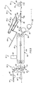
- Fig. 1 is a schematic plan view of a sheet material handling apparatus constructed in accordance with the present invention;
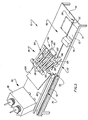
- Fig. 2 is a pictorial illustration of the sheet material handling apparatus of Fig. 1;
- Fig. 3 is a simplified schematic illustration of a portion of the sheet material handling apparatus of Fig. 2 and depicting the relationship between a reject assembly, and a stitcher assembly;
- Fig. 4 is an enlarged schematic illustration depicting an apparatus for moving a ramp in the reject assembly between a retracted position and an extended position;
- Fig. 5 is a schematic illustration depicting the relationship between the reject assembly, a pair of belts for moving a signature to the stitching station, and a folder assembly; and
- Fig. 6 is a schematic illustration of a control circuit used in the apparatus.
- An
apparatus 10 for collating groups ofsheets 12 is illustrated in Figs. 1 and 2. Theapparatus 10 includes a supply means for supplying sheets of material. The supply means comprises a plurality of sheet material supply hoppers 14. The hoppers 14 are disposed in a linear array along a support means which is asurface 16 which slopes downwardly away from the hoppers to aguide rail 18. Asheet feed mechanism 20 is provided to feed sheets from each of the hoppers 14 onto thesupport surface 16. - A
main conveyor assembly 24 is provided to sequentially move the groups ofsheets 12 along thesupport surface 16 past each of the hoppers 14. Themain conveyor assembly 24 includes a plurality ofpusher fingers 26 which project upwardly from thesupport surface 16 and engage the trailing edges of each of the groups ofsheets 12 to push them along the support surface 16 (see Figs. 2 and 3). Thepusher fingers 26 are connected with a continuous chain 30 (Fig. 5) having an upper run which extends past each of the hoppers 14 to a transfer station 32 (see Fig. 3) where the sheets are transferred from themain conveyor 24 to asecondary conveyor 36. - The
secondary conveyor assembly 36 includes upper and lower belts 40 and 42 (Figs. 3 and 5) which engage the leading edge portion of a group of sheets at thetransfer station 32 and accelerate the groups of sheets away from apusher finger 26 to astitching station 44. During movement from thetransfer station 32 to thestitching station 44, the group of sheets is clamped between the upper andlower belts 40 and 42 of thesecondary conveyor 36 to hold the-sheets against movement relative to each other. Shortly before the sheets are positioned relative to astapling apparatus 48 at thestitching station 44, the upper belt 40 is moved upwardly away from thelower belt 42 to release the sheets. - A register finger (not shown) then engages the trailing edge portions of the released sheets to register the sheets rotative to the
stitching apparatus 48. The sheets are then stitched and again clamped by thebelts 40 and 42. Thebelts 40 and 42 move the sheets to a folding station 52 (Fig. 5). The manner in which each group of sheets is clamped by thebelts 40 and 42 and then released and registered at thestitching station 44 is the same as disclosed in GB-A-2092992. - At the
stitching station 44, the groups of sheets are either saddle, side or corner stitched. If a group of sheets is corner or side stitched, the group of sheets moves through the folding station 52 to a lower discharge conveyor assembly 56 (Fig. 5) without being folded. However, if a group of sheets is saddle stitched at thestitching station 44, the group of sheets is folded by a buckle folder assembly 60 and trimmed by a knife 62 at the folding station 52 and then moved to an upperdischarge conveyor assembly 64. The general construction and mode of operation of the buckle folder 60 and trimming knife 62 is the same as is disclosed in U.S. Patent Nos. 3,554,531 and 3,627,305. - In accordance with a feature of the present invention, a
reject assembly 70 is provided at a - reject station 72 (see Figs. 2, 3 and 5) located between the hoppers 14 andstitching station 44. Thereject assembly 70 receives groups of sheets containing more or less than a predetermined number of sheets so that these incorrectly formed groups of sheets do not pass through thestitcher assembly 48 and folder 60. By using thereject assembly 70 to receive groups of sheets having either more or less than a predetermined number of sheets, it is not necessary to stop operation of the sheetmaterial handling apparatus 10 and remove the incorrectly formed groups of sheets. Of course, this increases the output of the sheetmaterial handling apparatus 10. - A
caliper assembly 76 is provided at an inspection station 78 (Fig. 3) which is disposed immediately before thereject station 72. Thecaliper assembly 76 detects whether a group of sheets being moved by themain conveyor assembly 24 contains (i) a desired number of sheets or (ii) more or less than the desired number of sheets. If thecaliper assembly 76 detects the desired number of sheets in a group, the group of sheets passes through thereject station 72 to thetransfer station 32 andstitching station 44. However, if a group of sheets contains either more or less than the desired number of sheets, thereject assembly 70 removes the group of sheets from the stream of sheets moving toward thestitching station 44. - The
reject assembly 70 includes areject ramp 84 which is movable between a retracted position shown in solid lines in Figs. 4 and 5 and extended position shown in dashed lines in Figs. 4 and 5. As best shown in Fig. 3, thereject ramp 86 includes two portions located on opposite sides of the path ofpushers 26. These enable both wide and narrow sheets to be readily rejected by the ramp. - When the
reject ramp 84 is in the retracted position, theupper side 86 of thereject ramp 84 is in a coplanar relationship with themain support surface 16. Therefore, when a group of sheets containing a predetermined number of sheets is moved through thereject station 72 by themain conveyor 24, thereject ramp 84 cooperates with themain support surface 16 to support the group of sheets. - When the
caliper assembly 76 detects that a group of sheets contains more or less than a desired number of sheets, a ramp actuator assembly 90 (see Fig. 4) moves thereject ramp 84 from the retracted or lowered position shown in solid lines in Fig. 4 to the raised or extended position shown in dashed lines in Fig. 4. When thereject ramp 84 is in the raised position, the ramp extends upwardly from themain support surface 16 to areject conveyor assembly 94. Thereject conveyor assembly 94 includes a plurality ofupper belts 96 which cooperate with a plurality oflower belts 98 to define an inlet nip 100 (see Fig. 4) adjacent to the upper end of the raisedreject ramp 84. - When a group of sheets containing either more or less than a predetermined of sheets is to be moved along the
main support surface 16 bypusher finger 26, theramp 84 is raised and the pusher finger moves the groups of sheets up the ramp. As the improperly formed group of sheets move up thereject ramp 84, the leading end portion of the group of sheets enters thenip 100 between thebelts Belts pusher fingers 26 moves the improperly formed group ofsheet 12 along themain support surface 16. Therefore, when a group of sheets containing more or less than the predetermined number of sheets enters thenip 100, the group of sheets is accelerated and moved away from the pusher finger. - The improperly formed group of sheets is discharged onto a support bin or
tray 104. Since the group of sheets discharged onto thesupport tray 104 has not been stapled and/or folded, the sheets can be redistributed to the hoppers 14 and subsequently used to form a group of sheets containing the desired number of sheets. - It is preferred to have the
reject ramp 84 move upwardly from a coplanar relationship with themain support surface 16 to an upwardly projecting extended position. This is because theramp 84 can be moved from the retracted position to the extended position while a group of sheets having either more or less than a predetermined number of sheets is being moved onto the ramp by themain conveyor assembly 24. Similarly, thereject ramp 84 can move through at least a portion of the distance from the extended position to the retracted position with a portion of a group of sheets containing a desired number of sheets on the ramp. This tends to maximize the amount of time available for thereject ramp 84 to be moved between the retracted and extended positions. However, it is contemplated that theramp 84 could be moved downwardly from a retracted position in which the ramp is disposed above thesupport surface 16. - When the sheet
material handling apparatus 10 is being operated to sequentially stitch groups of sheets, apusher finger 26 moves from the right end (as viewed in Figs. 1 and 2) of thesupport surface 16 past each of the hoppers 14 toward thereject station 72 which is disposed between the hoppers 14 and thestitching station 44. As apusher finger 26 moves past each of the hoppers 14 in turn, thesheet feed assembly 20 is operated to feed a sheet from the hopper onto thesupport surface 16 immediately ahead of the pusher finger. Therefore as thepusher finger 26 moves along thesupport surface 16, a group of sheets is accumulated ahead of the pusher finger. If it is desired to assemble a group of sheets containing a smaller number of sheets than the number of hoppers 14, some of the hoppers could be left empty and the sheet feed mechanism rendered ineffective to feed sheets from the empty hoppers. - After the
pusher finger 26 has moved past each of the hoppers 14, the group of sheets is pushed into the inspection station 78 (Fig. 5). Thecaliper assembly 76 then senses the thickness of the group of sheets to determined whether or not there is a desired number of sheets in the group of sheets. Assuming that the desired number of sheets is in the group of sheets, thereject ramp 84 remains in the retracted position shown in solid lines in Fig. 5. Thepusher finger 26 then pushes the group of sheets along themain support surface 16 over theupper side 86 of thereject ramp 84 which is disposed in a coplanar relationship with themain support surface 16. - After the correctly formed group of sheets has been pushed through the
reject station 72, it enters thetransfer station 32 where the group of sheets is engaged by thesecondary conveyor assembly 36 and moved to thestitching station 44. At thestitching station 44, the group of sheets is either saddle, side or corner stitched. Assuming that the group of sheets is saddle stitched, the buckle folder 60 (Fig. 5) is set for the size of the sheets and agate 110 is closed to block movement of the sheets to the lower discharge conveyor assembly 56. The group of sheets then enters the buckle folder 60 and a leading edge of the group of sheets engages a stop 112. A fold is then formed in a known manner at a nip between a pair ofrollers upper discharge conveyor 64. - If a group of sheets is corner or side stitched at the
stitching station 44, the group of sheets is not folded. Therefore, when sheets are being either side or corner stitched, thefolder gate 110 is moved from the closed position shown in solid lines in Fig. 5 to the open position shown in dashed lines in Fig. 5. This results in saddle or side stitched groups of sheets moving through the folder 60 to the lower discharge conveyor 56 without being folded. - If a group of sheets being pushed by a
finger 26 to theinspection station 78 contains more of less than the desired number of sheets, thecaliper assembly 76 provides an output signal. This signal causes theramp actuator assembly 90 to move thereject ramp 84 from the retracted position shown in solid lines in Fig. 4 to the extended position shown in dashed lines in Fig. 4. Thepusher finger 26 the pushes the improperly formed group of sheets up theramp 84 into thenip 100 formed between thebelts belts tray 104. - The
belts main conveyor assembly 24. Therefore, the group of sheets is moved upwardly away from thepusher finger 26. Thepusher finger 26 then moves through an opening 120 (Fig. 3) formed betweenrectangular sections reject ramp 84. Therefore, the pusher finger moves through thereject station 72 to thetransfer station 32 without pushing an improperly formed group of sheets to thetransfer station 32. - When the
caliper assembly 76 detects that a group of sheets having more or less than a predetermined number of sheets is being moved toward thereject station 72 by apusher finger 26, a signal from the caliper assembly renders thestitcher assembly 48 ineffective to feed wire to staple on the next succeeding cycle of operation. Since the group of sheets which would normally enter thestitching station 44 in the next succeeding cycle is retained at thereject station 72, there will not be any sheets atthestitching station 44 for thestitcher assembly 48 to stitch on the next succeeding cycle of operation. Since the signal from thecaliper assembly 76 rendered thestitcher assembly 48 ineffective to feed wire, unused staples are not accumulated at the stitcher assembly during the next operating cycle. Although thestitcher assembly 48 could be disabled in many different ways, it is contemplated that it will be disabled by energizing a solenoid to shift a wire feed dog in a manner similar to that shown in U.S. Patent No. 3,561,752. - The ramp actuator assembly 90 (Fig. 4) moves the
ramp 86 between the retracted and extended positions. Theramp actuator assembly 90 is driven from a continuously rotating main drive shaft 130 by achain 132. When a single revolution clutch assembly, shown schematically at 136, is actuated, drive forces are transmitted from asprocket 134 to rotate a shaft 140 through one revolution. The drive shaft 140 is connected with asprocket 142 andchain 144 which drives thebelts reject conveyor assembly 94 through asprocket 146 and gears 148 and 149. - Rotation of the drive shaft 140 (Fig. 4) also effects actuation of a
linkage 150 to move theramp 84 from the retracted position to the extended position. Thus, a cam 152 connected with the shaft 140 is rotated through a single revolution with the shaft each time the clutch 136 is actuated. As the cam 152 rotates, a cam follower 156 moves upwardlyto pivot a lever 160 in a counterclockwise direction (as viewed in Fig. 4) and move an actuator arm 162 upwardly. Upward movement of the actuator arm 162 pivots thereject ramp 84 in a clockwise direction (as viewed in Fig. 4) about apivot connection 164. This results in thereject ramp 84 being moved to its extended position. - After the group of sheets has been moved up the
ramp 84 to thereject conveyor assembly 94, continued rotation of the drive shaft 140 through a single revolution causes the cam follower 156 to move downwardly. Therefore thereject ramp 84 is pivoted in a counterclockwise direction (as viewed in Fig. 4). At the end of a single revolution of the drive shaft 140, thereject ramp 84 is back at the retracted position shown in solid lines in Fig. 4 and the improperly formed group of sheets has been moved to thereject tray 104. - Since the
chain 144 is driven only when the single revolution clutch assembly is actuated, it should be clear that thebelts - Assuming that the next succeeding groups of sheets is of the correct size, the
single revolution clutch 136 is not engaged. Therefore, rotation of thesprocket 134 by thechain 132 is nottransmitted to the shaft 140 and thereject ramp 84 remains in the retracted position shown in Fig. 4. - The
single revolution clutch 136 has a construction such that if it is actuated part way through one cycle of operation of thecollator 10, the clutch is not engaged until the beginning of the next succeeding cycle. Therefore upon detection of an improperly formed group of sheets, a signal from thecaliper assembly 76 energizes a solenoid which actuates the one-way clutch 136 part way through one cycle of operation of thecollator 10. However, the clutch itself does not become effective to drive the shaft 140 until the beginning of the next succeeding cycle. Although the one-way clutch 136 could have many different constructions, the preferred clutch is the "CB-6" one-way clutch sold by the Warner Electric Brake & Clutch Company of Beloit, Wisconsin. - A
control circuit 170 for the collator of the present invention is illustrated schematically in Fig. 6. Thecontrol circuit 170 includes asolenoid 174 which is energized to actuate thesingle revolution clutch 136. A stitcherfeed disabling solenoid 176 is energized to render thestitcher assembly 48 ineffective to feed wire when a group of sheets is rejected. - The
control circuit 170 also includes astart switch 180. Thestart switch 180 is a double pole switch having two movable switch contacts, one designated 182 and the other designated 183. When thecontacts relays relays switch contacts book inspector switch 195. Thecontacts - Also, when the
relays relays motor starter relay 200 which starts the machine. - The
inspection switch 195 operates to determine when a book of correct thickness is being handled by the machine and when a book of incorrect thickness is being handled by the machine. When a book is being inspectedswitch contacts open contact 201 of theinspection switch 195 will close while the normally closedcontacts 202 will remain closed. Thus, the flow of current to therelays - If an incorrect thickness book is detected by the
inspector switch 195, when thecontacts relays contact 201 will remain open and contact 202 will remain closed. If the book is too thick, the normally closedcontacts 202 will be forced open and 201 will be forced closed. If thecontact 201 remains openorthe contact 202 opens, one of the inspector relays 190 or 191 will be de-energized.Relay 191 will be de-energized if the gather or book is too thin andrelay 190 will be de-energized if the gather is too thick. - When a book which is too thin or too thick is sensed, further controls in the machine depend upon the positioning of a
mode selector switch 210. Theselector switch 210 hasswitch elements contacts - When the
contacts selector switch 210 are in position 210A or 210B, current is supplied between the power line A and B to maintain themotor starter relay 200 energized. When themotor starter relay 200 was originally energized, the normally open motor starter relay contacts 200-1 were closed. Thus, when thecontacts switch 210 are in positions 210A or 21 OB, current flows from the power line A to the power lineBthrough switch contact 213 and then through the now closed contacts 200-1 of the motor starter relay and through themotor starter relay 200. Thus, in the all reject or normal reject modes, themotor starter relay 200 is maintained energized due to the fact that there is no interruption of current to the motor starter relay. Thus, the machine continues to operate. When therelays clutch solenoid 174. Thus on original closing ofswitch 180, the clutch solenoid 174could not be energized because these contacts, namely contacts 190-3 and 191-3, were opened. - However, when
relay contacts inspector switch 195 being open, either contacts 190-3 or 191-3 will be closed. Closing of either of the contacts 190-3 or 191-3 causes an energization of theclutch solenoid 174 if theselector switch 210 is in the normal reject position 210B. Current will flow from the power line A through thecontacts clutch solenoid 174 to the power line B. This of course results in the shaft actuated by the clutch to rotate for a single revolution and of course results in operation of the reject ramp causing a rejection of the defective book. - Near completion of rotation of the one revolution of the clutch shaft a stop stitch switch designated 230 will be energized by a suitable mechanical mechanism actuated from rotation of the shaft. Specifically the
switch 230 will be closed. When theswitch 230 is closed, current will pass from the power line A through theselector switch 210 through the now closedswitch 230 and to thesolenoid 176 thus effecting energization of thesolenoid 176. Energization of thesolenoid 176 will also effect energization of a stop stitch holding relay 231. Energization of the relay 231 will cause normally open contacts 231-1 thereof to close. The relay 231 is in a series circuit with a cam operated normally closedmicroswitch 232. A current thus is completed through the cam operatedswitch 232, the now closed contacts 231-1 of the relay 231 and the relay 231. This results in the relay 231 remaining energized even thoughswitch 230 opens and a disengagement of the wire draw in the stitcher head so as to cause no stitching to occur when the rejected gather would have been in the stitching cycle of operation in the machine. - In the event a correct thickness book is being handled by the machine, switch 230 will not be closed because
clutch solenoid 174 will not rotate. Thus, a correct thickness book will be stitched. - When the stitching cycle is completed a cam not shown on the machine main drive shaft will cause the
microswitch 232 to open. This de-energizes the holding relay 231 and thus the circuit will be ready for the next cycle of operation of the machine. - As noted above, one of the inspection relays 190, 191 are de-energized by the detection of an incorrect thickness book. Interposed between the
relays circuit 170 is a normallyopen microswitch 250. The normallyopen microswitch 250 is operated by a cam on the main drive shaft of the machine and is closed by the cam. - When the switch is closed, a current is provided through the
switch 250 to energize thede-energized relay switch 250 is closed at the appropriate time in the cycle of the machine so as to have therelay - During the interval between when the
stop stitch solenoid 176 is energized and the holding relay 231 is energized, a cam (not shown) on the main drive shaft of the apparatus will close a normallyopen microswitch 260. Closing of the normallyopen microswitch 260 will send an impulse current to a counter (not shown) which counts the correct number of books delivered by the machine. The current to the counter travels through normally closed contacts 231-2 of the stop stitch holding relay 231 andswitch 260. If the stop stitch holding relay 231 is energized indicating a gather has been rejected, the normally closed contacts 231-2 open interrupting the flow of current to theswitch 260. Thus, an incorrect thickness book will not be counted. - In the event that for some reason, such as set up or otherwise, it is desired that no stitching of the book occur, the
stop stitch solenoid 176 can be energized by manually closing normallyopen switch 270. Whenswitch 270 is energized a current will flow to thestop stitch solenoid 176 and relay 231. As a result, stitching of the book will not occur. - Also, when the circuit is set up for a normal reject mode, a light 271 will be energized continuously through the contacts of the
selector switch 210. Thus, the light 271 will indicate that books are being rejected in the normal reject mode (position 210B of thecontacts 213, 214). When theselector switch 210 is in the all reject mode (position 210A of thecontacts 213, 214), the light 271 will be energized throughinspector switch contact 192 only when the machine is operating to inspect books. Theswitch contact 192 moves to close this circuit on each cycle, and thus during inspection the light 271 will operate periodically. - Also the circuit is constructed so that when the machine is in the no reject mode, namely the
switch 210 is in the normal position shown in full line in Fig. 6, the machine will stop on a thin or thick book which is sensed by theinspector switch 195. Specifically, when theswitch 210 is in the no reject mode and a double or miss is sensed, relay 190 or 191 is de-energized. Whenrelay motor starter 200 stops, thus the machine stops. Accordingly, depending upon the position of theselector switch 210, the operation of the machine will vary. - In view of the foregoing description it is apparent that the
collator 10 sequentiallystitches groups 12 of sheets. Thecollator 10 includes a support surface which extends past a plurality of hoppers 14 to astitching station 44. Sheets are sequentially fed from the hoppers 14 to formgroups 12 of sheets on thesupport surface 16. Amain conveyor assembly 24 sequentially pushes groups of sheets along thesupport surface 16 to areject station 72. Groups of sheets containing more or less than a predetermined number of sheets are rejected at thereject station 72. Thegroups 12 of sheets containing the predetermined number of sheets are moved to atransfer station 32 where they are engaged by asecondary conveyor assembly 36 which moves them to astitching station 44. - At the
reject station 72, aramp 84 is movable between a retracted position and an extended position. When thereject ramp 84 is in the retracted position, it cooperates with themain support surface 16 to support agroup 12 of sheets containing the predetermined number of sheets as the group moves to thestitching station 44. When theramp 84 is in the extended position, it projects upwardly from thesupport surface 16 to thereject conveyor 94. Themain conveyor 24 pushesgroups 12 of sheets containing more or less than the predetermined number of sheets up thereject ramp 84 to thereject conveyor 94.
Claims (3)
Priority Applications (1)
| Application Number | Priority Date | Filing Date | Title |
|---|---|---|---|
| AT83111530T ATE26961T1 (en) | 1982-12-10 | 1983-11-18 | DEFLECTOR FOR AN APPARATUS FOR HANDLING SHEET-LIKE MATERIAL. |
Applications Claiming Priority (2)
| Application Number | Priority Date | Filing Date | Title |
|---|---|---|---|
| US06/448,432 US4499834A (en) | 1982-12-10 | 1982-12-10 | Reject assembly for sheet material handling apparatus |
| US448432 | 1982-12-10 |
Publications (2)
| Publication Number | Publication Date |
|---|---|
| EP0113011A1 EP0113011A1 (en) | 1984-07-11 |
| EP0113011B1 true EP0113011B1 (en) | 1987-05-06 |
Family
ID=23780286
Family Applications (1)
| Application Number | Title | Priority Date | Filing Date |
|---|---|---|---|
| EP83111530A Expired EP0113011B1 (en) | 1982-12-10 | 1983-11-18 | Reject assembly for sheet material handling apparatus |
Country Status (4)
| Country | Link |
|---|---|
| US (1) | US4499834A (en) |
| EP (1) | EP0113011B1 (en) |
| AT (1) | ATE26961T1 (en) |
| DE (1) | DE3371325D1 (en) |
Families Citing this family (29)
| Publication number | Priority date | Publication date | Assignee | Title |
|---|---|---|---|---|
| DE3427570A1 (en) * | 1984-07-26 | 1986-02-06 | M.A.N.- Roland Druckmaschinen AG, 6050 Offenbach | DEVICE FOR FOLDING AND PROCESSING PRINTED EXPLARENTS |
| US4587913A (en) * | 1985-04-08 | 1986-05-13 | Union Special Corporation | Automatic sewing apparatus |
| NL192091C (en) * | 1985-04-18 | 1997-02-04 | Nederland Ptt | Change for a sorting device with one or more vanes. |
| US4721296A (en) * | 1986-05-27 | 1988-01-26 | Harris Graphics Corporation | Sheet material handling apparatus |
| DE3624994A1 (en) * | 1986-07-24 | 1988-02-04 | Schmale Carl Gmbh & Co Kg | METHOD AND DEVICE FOR CROSS-CUTTING, DOUBLE-SIDED HEMING AND SEWING OF FLAT MATERIALS, IN PARTICULAR FROTTEEWARE |
| US4729555A (en) * | 1986-10-09 | 1988-03-08 | Sew Simple Systems, Inc. | Compact high speed stacker |
| US4753429A (en) * | 1986-11-13 | 1988-06-28 | Pitney Bowes Inc. | Collating station for inserting machine |
| DE3710025A1 (en) * | 1987-03-27 | 1988-10-13 | Schmale Carl Gmbh & Co Kg | METHOD AND DEVICE FOR THE FULLY AUTOMATIC PRODUCTION OF TEXTILE PRODUCTS BORN AT ITS EDGES |
| US4765502A (en) * | 1987-06-19 | 1988-08-23 | Pitney Bowes Inc. | Apparatus for nonstop operation of an inserter system with multiple document feeding capability |
| US4856444A (en) * | 1987-10-21 | 1989-08-15 | Sew Simple Systems, Inc. | Fitted sheet hemmer |
| IT1217410B (en) * | 1988-04-13 | 1990-03-22 | Plastiver Di Giovanni E Vittor | PROCEDURE AND PLANT FOR THE COLLECTION OF BOOK SIGNATURES, MAGAZINES AND RELATED |
| US4986521A (en) * | 1989-03-06 | 1991-01-22 | Mccain Manufacturing Corp. | Reject device for a signature gathering machine |
| US5545381A (en) * | 1991-01-31 | 1996-08-13 | Ricoh Company, Ltd. | Device for regenerating printed sheet-like recording medium |
| US5183246A (en) * | 1991-10-21 | 1993-02-02 | Pitney Bowes Inc. | Diverting apparatus and method for in-line inserting equipment |
| US5295586A (en) * | 1991-12-16 | 1994-03-22 | E. I. Du Pont De Nemours And Company | Apparatus for separating a sheet from an array of sheets |
| US5476053A (en) * | 1994-09-27 | 1995-12-19 | Sew Simple Systems, Inc. | Flat sheet hemming method and folding and separating apparatus |
| WO1997031341A1 (en) * | 1996-02-22 | 1997-08-28 | As Beteiligungs Gesellschaft Mbh | Apparatus for separating and sorting of bank notes |
| DE19730758C2 (en) * | 1997-07-17 | 1999-04-29 | Windmoeller & Hoelscher | Device for separating faulty and for forming stacks from faultless flat objects |
| US6224048B1 (en) * | 1998-01-20 | 2001-05-01 | Electronics For Imaging, Inc. | Mixed format document finishing system responsive to a single page having an encoded document assembly specification |
| US6386537B1 (en) | 2000-04-13 | 2002-05-14 | Pitney Bowes Inc. | Sheet accumulator with diverting mechanisms |
| DE50313398D1 (en) * | 2003-10-16 | 2011-02-17 | Mueller Martini Holding Ag | Method and device for producing selectively compiled printed products |
| US7607649B2 (en) | 2005-10-03 | 2009-10-27 | Bowe Bell + Howell Company | Apparatuses and methods for staging and processing documents for sheet processing |
| US7637490B2 (en) | 2005-10-03 | 2009-12-29 | Bowe Bell + Howell Company | Inserting systems and methods |
| US7396006B2 (en) | 2005-10-03 | 2008-07-08 | Bowe Bell + Howell Company | Apparatus for assembly of document sets into a single collated packet |
| US7607653B2 (en) | 2006-10-12 | 2009-10-27 | Bowe Bell + Howell Company | Systems and methods for maintaining the density of grouped sheet articles |
| US7454882B2 (en) | 2006-10-12 | 2008-11-25 | Bowe Bell + Howell Company | Methods for variably opening envelopes |
| US7662080B2 (en) | 2006-10-12 | 2010-02-16 | Bowe Bell & Howell | Crease roller apparatuses and methods for using same |
| US8939443B2 (en) | 2013-03-15 | 2015-01-27 | R.R. Donnelley & Sons Company | Imaging apparatus and methods for bindery systems |
| EP3599103B1 (en) * | 2018-07-25 | 2020-10-14 | Müller Martini Holding AG | Gathering and stitching machine for printed products |
Citations (2)
| Publication number | Priority date | Publication date | Assignee | Title |
|---|---|---|---|---|
| US3627305A (en) * | 1969-06-17 | 1971-12-14 | Harris Intertype Corp | Collator folder register assembly |
| GB2092995A (en) * | 1981-02-17 | 1982-08-25 | Harris Corp | Signature feeding and stitching method and apparatus |
Family Cites Families (7)
| Publication number | Priority date | Publication date | Assignee | Title |
|---|---|---|---|---|
| US29105A (en) * | 1860-07-10 | Improvement in horse-rakes | ||
| US3038606A (en) * | 1957-04-18 | 1962-06-12 | Electronic Associates Ltd | Automatic level inspector |
| US3554531A (en) * | 1968-06-18 | 1971-01-12 | Harris Intertype Corp | Binder assembly |
| US3561752A (en) * | 1968-07-29 | 1971-02-09 | Chicago Machinery Lab Inc | Signature machines |
| US3664655A (en) * | 1970-09-25 | 1972-05-23 | Mccain Mfg Co | Caliper system for signature machines |
| US3819173A (en) * | 1971-09-01 | 1974-06-25 | Harris Intertype Corp | Method and apparatus for producing magazines or the like |
| USRE29105E (en) | 1973-05-07 | 1977-01-11 | Harris Corporation | Apparatus for making books |
-
1982
- 1982-12-10 US US06/448,432 patent/US4499834A/en not_active Expired - Fee Related
-
1983
- 1983-11-18 AT AT83111530T patent/ATE26961T1/en not_active IP Right Cessation
- 1983-11-18 DE DE8383111530T patent/DE3371325D1/en not_active Expired
- 1983-11-18 EP EP83111530A patent/EP0113011B1/en not_active Expired
Patent Citations (2)
| Publication number | Priority date | Publication date | Assignee | Title |
|---|---|---|---|---|
| US3627305A (en) * | 1969-06-17 | 1971-12-14 | Harris Intertype Corp | Collator folder register assembly |
| GB2092995A (en) * | 1981-02-17 | 1982-08-25 | Harris Corp | Signature feeding and stitching method and apparatus |
Also Published As
| Publication number | Publication date |
|---|---|
| EP0113011A1 (en) | 1984-07-11 |
| DE3371325D1 (en) | 1987-06-11 |
| US4499834A (en) | 1985-02-19 |
| ATE26961T1 (en) | 1987-05-15 |
Similar Documents
| Publication | Publication Date | Title |
|---|---|---|
| US4499834A (en) | Reject assembly for sheet material handling apparatus | |
| EP0568244B1 (en) | Sheet inserter and methods of inserting sheets into a continuous stream of sheets | |
| EP0371403B1 (en) | A sheet post-processing apparatus and image forming apparatus | |
| EP1090778B1 (en) | Sheet stapler unit and sheet processing device | |
| JP3122518B2 (en) | Paper stacking equipment | |
| US6994337B1 (en) | Book bindery and trimming apparatus | |
| JPS5882819A (en) | Device for automatically treating laminate of sheet, on which paper money, etc. are printed, to separate bundle of paper money, etc. | |
| JPS5934908Y2 (en) | Collector | |
| US5501442A (en) | Dual mode tamper/offsetter | |
| JP2001048411A (en) | Collating device | |
| JPS63154578A (en) | Sheet matching device | |
| US5362200A (en) | Sheet transporting device for a sorter | |
| US5374043A (en) | Sorter with stapler actived release gate mechanism | |
| JP4350289B2 (en) | Sheet processing apparatus and image forming apparatus | |
| US4244564A (en) | Control system for a collator | |
| JP3399667B2 (en) | Paper post-processing equipment | |
| EP0673868B1 (en) | Integral disk type inverter-stacker and stapler | |
| JP4011977B2 (en) | Paper processing apparatus and image forming system | |
| JPH0611591B2 (en) | Sheet aftertreatment device | |
| JP3939876B2 (en) | Paper processing device | |
| JP3619684B2 (en) | Sheet processing apparatus and image forming apparatus | |
| JP3658509B2 (en) | Paper loading device | |
| JP2863289B2 (en) | Paper binding device | |
| JPH0748607Y2 (en) | Sheet stacking device | |
| JP3441897B2 (en) | Paper post-processing equipment |
Legal Events
| Date | Code | Title | Description |
|---|---|---|---|
| PUAI | Public reference made under article 153(3) epc to a published international application that has entered the european phase |
Free format text: ORIGINAL CODE: 0009012 |
|
| AK | Designated contracting states |
Designated state(s): AT BE CH DE FR GB LI NL SE |
|
| 17P | Request for examination filed |
Effective date: 19840822 |
|
| GRAA | (expected) grant |
Free format text: ORIGINAL CODE: 0009210 |
|
| AK | Designated contracting states |
Kind code of ref document: B1 Designated state(s): AT BE CH DE FR GB LI NL SE |
|
| REF | Corresponds to: |
Ref document number: 26961 Country of ref document: AT Date of ref document: 19870515 Kind code of ref document: T |
|
| REF | Corresponds to: |
Ref document number: 3371325 Country of ref document: DE Date of ref document: 19870611 |
|
| ET | Fr: translation filed | ||
| PGFP | Annual fee paid to national office [announced via postgrant information from national office to epo] |
Ref country code: NL Payment date: 19871130 Year of fee payment: 5 |
|
| PLBE | No opposition filed within time limit |
Free format text: ORIGINAL CODE: 0009261 |
|
| STAA | Information on the status of an ep patent application or granted ep patent |
Free format text: STATUS: NO OPPOSITION FILED WITHIN TIME LIMIT |
|
| 26N | No opposition filed | ||
| REG | Reference to a national code |
Ref country code: CH Ref legal event code: PUE Owner name: AM INTERNATIONAL INCORPORATED |
|
| PG25 | Lapsed in a contracting state [announced via postgrant information from national office to epo] |
Ref country code: AT Effective date: 19891118 |
|
| PG25 | Lapsed in a contracting state [announced via postgrant information from national office to epo] |
Ref country code: SE Effective date: 19891119 |
|
| PG25 | Lapsed in a contracting state [announced via postgrant information from national office to epo] |
Ref country code: BE Effective date: 19891130 |
|
| REG | Reference to a national code |
Ref country code: FR Ref legal event code: TP |
|
| PGFP | Annual fee paid to national office [announced via postgrant information from national office to epo] |
Ref country code: CH Payment date: 19900108 Year of fee payment: 7 |
|
| REG | Reference to a national code |
Ref country code: GB Ref legal event code: 732 |
|
| NLS | Nl: assignments of ep-patents |
Owner name: AM INTERNATIONAL INCORPORATED TE CHICAGO, ILLINOIS |
|
| BERE | Be: lapsed |
Owner name: AM INTERNATIONAL INC. Effective date: 19891130 |
|
| PG25 | Lapsed in a contracting state [announced via postgrant information from national office to epo] |
Ref country code: NL Effective date: 19900601 |
|
| NLV4 | Nl: lapsed or anulled due to non-payment of the annual fee | ||
| PG25 | Lapsed in a contracting state [announced via postgrant information from national office to epo] |
Ref country code: LI Effective date: 19901130 Ref country code: CH Effective date: 19901130 |
|
| REG | Reference to a national code |
Ref country code: CH Ref legal event code: PL |
|
| PGFP | Annual fee paid to national office [announced via postgrant information from national office to epo] |
Ref country code: GB Payment date: 19941017 Year of fee payment: 12 |
|
| PGFP | Annual fee paid to national office [announced via postgrant information from national office to epo] |
Ref country code: DE Payment date: 19941130 Year of fee payment: 12 |
|
| EUG | Se: european patent has lapsed |
Ref document number: 83111530.8 Effective date: 19900705 |
|
| PG25 | Lapsed in a contracting state [announced via postgrant information from national office to epo] |
Ref country code: GB Effective date: 19951118 |
|
| GBPC | Gb: european patent ceased through non-payment of renewal fee |
Effective date: 19951118 |
|
| PG25 | Lapsed in a contracting state [announced via postgrant information from national office to epo] |
Ref country code: FR Effective date: 19960731 |
|
| PG25 | Lapsed in a contracting state [announced via postgrant information from national office to epo] |
Ref country code: DE Effective date: 19960801 |
|
| REG | Reference to a national code |
Ref country code: FR Ref legal event code: ST |
|
| PGFP | Annual fee paid to national office [announced via postgrant information from national office to epo] |
Ref country code: FR Payment date: 19971119 Year of fee payment: 15 |