EP0112763A1 - High voltage power supply system for a load such as an X-ray generator - Google Patents
High voltage power supply system for a load such as an X-ray generator Download PDFInfo
- Publication number
- EP0112763A1 EP0112763A1 EP83402407A EP83402407A EP0112763A1 EP 0112763 A1 EP0112763 A1 EP 0112763A1 EP 83402407 A EP83402407 A EP 83402407A EP 83402407 A EP83402407 A EP 83402407A EP 0112763 A1 EP0112763 A1 EP 0112763A1
- Authority
- EP
- European Patent Office
- Prior art keywords
- inverter
- controlled
- voltage
- load
- switching means
- Prior art date
- Legal status (The legal status is an assumption and is not a legal conclusion. Google has not performed a legal analysis and makes no representation as to the accuracy of the status listed.)
- Withdrawn
Links
Images
Classifications
-
- H—ELECTRICITY
- H05—ELECTRIC TECHNIQUES NOT OTHERWISE PROVIDED FOR
- H05G—X-RAY TECHNIQUE
- H05G1/00—X-ray apparatus involving X-ray tubes; Circuits therefor
- H05G1/08—Electrical details
- H05G1/10—Power supply arrangements for feeding the X-ray tube
- H05G1/20—Power supply arrangements for feeding the X-ray tube with high-frequency ac; with pulse trains
-
- H—ELECTRICITY
- H02—GENERATION; CONVERSION OR DISTRIBUTION OF ELECTRIC POWER
- H02M—APPARATUS FOR CONVERSION BETWEEN AC AND AC, BETWEEN AC AND DC, OR BETWEEN DC AND DC, AND FOR USE WITH MAINS OR SIMILAR POWER SUPPLY SYSTEMS; CONVERSION OF DC OR AC INPUT POWER INTO SURGE OUTPUT POWER; CONTROL OR REGULATION THEREOF
- H02M3/00—Conversion of dc power input into dc power output
- H02M3/22—Conversion of dc power input into dc power output with intermediate conversion into ac
- H02M3/24—Conversion of dc power input into dc power output with intermediate conversion into ac by static converters
- H02M3/28—Conversion of dc power input into dc power output with intermediate conversion into ac by static converters using discharge tubes with control electrode or semiconductor devices with control electrode to produce the intermediate ac
- H02M3/305—Conversion of dc power input into dc power output with intermediate conversion into ac by static converters using discharge tubes with control electrode or semiconductor devices with control electrode to produce the intermediate ac using devices of a thyratron or thyristor type requiring extinguishing means
- H02M3/315—Conversion of dc power input into dc power output with intermediate conversion into ac by static converters using discharge tubes with control electrode or semiconductor devices with control electrode to produce the intermediate ac using devices of a thyratron or thyristor type requiring extinguishing means using semiconductor devices only
- H02M3/3155—Conversion of dc power input into dc power output with intermediate conversion into ac by static converters using discharge tubes with control electrode or semiconductor devices with control electrode to produce the intermediate ac using devices of a thyratron or thyristor type requiring extinguishing means using semiconductor devices only with automatic control of the output voltage or current
-
- H—ELECTRICITY
- H02—GENERATION; CONVERSION OR DISTRIBUTION OF ELECTRIC POWER
- H02M—APPARATUS FOR CONVERSION BETWEEN AC AND AC, BETWEEN AC AND DC, OR BETWEEN DC AND DC, AND FOR USE WITH MAINS OR SIMILAR POWER SUPPLY SYSTEMS; CONVERSION OF DC OR AC INPUT POWER INTO SURGE OUTPUT POWER; CONTROL OR REGULATION THEREOF
- H02M7/00—Conversion of ac power input into dc power output; Conversion of dc power input into ac power output
- H02M7/42—Conversion of dc power input into ac power output without possibility of reversal
- H02M7/44—Conversion of dc power input into ac power output without possibility of reversal by static converters
- H02M7/48—Conversion of dc power input into ac power output without possibility of reversal by static converters using discharge tubes with control electrode or semiconductor devices with control electrode
- H02M7/505—Conversion of dc power input into ac power output without possibility of reversal by static converters using discharge tubes with control electrode or semiconductor devices with control electrode using devices of a thyratron or thyristor type requiring extinguishing means
- H02M7/515—Conversion of dc power input into ac power output without possibility of reversal by static converters using discharge tubes with control electrode or semiconductor devices with control electrode using devices of a thyratron or thyristor type requiring extinguishing means using semiconductor devices only
- H02M7/5152—Conversion of dc power input into ac power output without possibility of reversal by static converters using discharge tubes with control electrode or semiconductor devices with control electrode using devices of a thyratron or thyristor type requiring extinguishing means using semiconductor devices only with separate extinguishing means
-
- H—ELECTRICITY
- H02—GENERATION; CONVERSION OR DISTRIBUTION OF ELECTRIC POWER
- H02M—APPARATUS FOR CONVERSION BETWEEN AC AND AC, BETWEEN AC AND DC, OR BETWEEN DC AND DC, AND FOR USE WITH MAINS OR SIMILAR POWER SUPPLY SYSTEMS; CONVERSION OF DC OR AC INPUT POWER INTO SURGE OUTPUT POWER; CONTROL OR REGULATION THEREOF
- H02M7/00—Conversion of ac power input into dc power output; Conversion of dc power input into ac power output
- H02M7/42—Conversion of dc power input into ac power output without possibility of reversal
- H02M7/44—Conversion of dc power input into ac power output without possibility of reversal by static converters
- H02M7/48—Conversion of dc power input into ac power output without possibility of reversal by static converters using discharge tubes with control electrode or semiconductor devices with control electrode
- H02M7/505—Conversion of dc power input into ac power output without possibility of reversal by static converters using discharge tubes with control electrode or semiconductor devices with control electrode using devices of a thyratron or thyristor type requiring extinguishing means
- H02M7/515—Conversion of dc power input into ac power output without possibility of reversal by static converters using discharge tubes with control electrode or semiconductor devices with control electrode using devices of a thyratron or thyristor type requiring extinguishing means using semiconductor devices only
- H02M7/523—Conversion of dc power input into ac power output without possibility of reversal by static converters using discharge tubes with control electrode or semiconductor devices with control electrode using devices of a thyratron or thyristor type requiring extinguishing means using semiconductor devices only with LC-resonance circuit in the main circuit
- H02M7/5233—Conversion of dc power input into ac power output without possibility of reversal by static converters using discharge tubes with control electrode or semiconductor devices with control electrode using devices of a thyratron or thyristor type requiring extinguishing means using semiconductor devices only with LC-resonance circuit in the main circuit the commutation elements being in a push-pull arrangement
- H02M7/5236—Conversion of dc power input into ac power output without possibility of reversal by static converters using discharge tubes with control electrode or semiconductor devices with control electrode using devices of a thyratron or thyristor type requiring extinguishing means using semiconductor devices only with LC-resonance circuit in the main circuit the commutation elements being in a push-pull arrangement in a series push-pull arrangement
-
- H—ELECTRICITY
- H05—ELECTRIC TECHNIQUES NOT OTHERWISE PROVIDED FOR
- H05G—X-RAY TECHNIQUE
- H05G1/00—X-ray apparatus involving X-ray tubes; Circuits therefor
- H05G1/08—Electrical details
- H05G1/26—Measuring, controlling or protecting
- H05G1/30—Controlling
- H05G1/32—Supply voltage of the X-ray apparatus or tube
Definitions
- the invention overcomes all of these drawbacks.
- the operating frequency of the inverter can be adjusted once and for all slightly lower than the resonance frequency of the above-mentioned oscillating circuit, which makes it possible to obtain a reduced residual ripple rate for the entire range of voltage variations. of the power system.
- the rectifier bridge is a simple Graetz diode bridge, which eliminates the use of expensive thyristors at this level.
- a single regulation loop controls the operation of the chopper.
- the operating frequency of the latter is high, of the order of a few kHz. Its speed of response is therefore much better than that of a Graetz bridge with thyristors operating at the network frequency.
- filtering is easier at this frequency and vis-à-vis the network, the system has better cos ⁇
- the common point of the resistors R 1 and R2 is connected to an input of a differential amplifier 20 which receives on its other input a reference voltage adjustable by a potentiometer P 1 .
- the output of amplifier 20 is connected to a conventional circuit 21 forming a driving pulse generator.
- These pulses of variable duration control thyristor Th 1 The triggering of the thyristor is controlled in synchronism with each rising edge of the pulse while the blocking of this same thyristor is controlled from each falling edge.
Landscapes
- Engineering & Computer Science (AREA)
- Power Engineering (AREA)
- Health & Medical Sciences (AREA)
- General Health & Medical Sciences (AREA)
- Toxicology (AREA)
- X-Ray Techniques (AREA)
- Inverter Devices (AREA)
Abstract
Selon l'invention, le système comporte un onduleur (12) du type à résonance, un pont redresseur (11) à diodes et une unique boucle de régulation (20, 21, 22, 24) commandant des moyens de commutation commandés (14), formant hacheur, interconnectés entre le pont redresseur et l'onduleur. Application à la radiologie.According to the invention, the system comprises an inverter (12) of the resonance type, a rectifier bridge (11) with diodes and a single regulation loop (20, 21, 22, 24) controlling controlled switching means (14) , forming a chopper, interconnected between the rectifier bridge and the inverter. Application to radiology.
Description
L'invention concerne un système d'alimentation haute tension d'une charge, cette charge pouvant être plus particulièrement un générateur de rayons X pour des applications médicales ou industrielles. L'invention vise plus particulièrement une simplification des moyens de réglage et de régulation de la tension appliquée à la charge ainsi qu'une réduction du taux d'ondulation résiduelle de cette tension.The invention relates to a high voltage power supply system for a load, this load possibly being more particularly an X-ray generator for medical or industrial applications. The invention relates more particularly to a simplification of the means for adjusting and regulating the voltage applied to the load as well as a reduction in the residual ripple rate of this voltage.
On connaît un système d'alimentation haute tension d'un générateur de rayons X essentiellement constitué par un pont redresseur, un onduleur du type à résonance alimenté par le pont redresseur et par des moyens de régulation et de réglage admettant comme tension d'erreur un signal représentatif de la tension appliquée aux bornes de la charge. Dans ce type de système, il est difficile de faire varier la tension délivrée à la charge sur toute la plage de variations requises. A titre d'exemple, on a proposé un système comportant deux boucles de régulation et de réglage, l'une agissant sur le pont redresseur pour faire varier la valeur de la tension continue appliquée à l'onduleur et l'autre agissant sur la fréquence de fonctionnement de l'onduleur même. La première boucle de régulation et de réglage permet donc un réglage grossier de tension tandis que la seconde permet un réglage fin. Un tel système est décrit en détail dans le brevet français n°2.451.149.There is known a high voltage power supply system for an X-ray generator essentially constituted by a rectifier bridge, an inverter of the resonance type supplied by the rectifier bridge and by regulation and adjustment means admitting as error voltage a signal representative of the voltage applied across the load. In this type of system, it is difficult to vary the voltage delivered to the load over the entire range of variations required. By way of example, a system has been proposed comprising two regulation and adjustment loops, one acting on the rectifier bridge to vary the value of the DC voltage applied to the inverter and the other acting on the frequency. of the inverter itself. The first regulation and adjustment loop therefore allows a rough tension adjustment while the second allows a fine adjustment. Such a system is described in detail in French Patent No. 2,451,149.
Ce système est compliqué parce qu'il nécessite deux boucles de régulation et de réglage. En outre, le pont redresseur doit être équipé de thyristors, ou de composants de commutation analogues, qui sont des dispositifs coûteux. Enfin et surtout, il y a un réel inconvénient à faire varier la fréquence de l'onduleur. En effet, le fonctionnement de celui-ci est optimal lorsque la fréquence d'oscillation est choisie légèrement inférieure à la fréquence de résonance d'un circuit oscillant incluant le primaire du transformateur élévateur de cet onduleur. En diminuant la fréquence de fonctionnement par rapport à cette valeur optimale, on arrive bien effectivement à faire décroître, dans une plage limitée, la tension de sortie délivrée par l'onduleur (c'est ce que réalise la seconde boucle de régulation et de réglage précitée) mais au prix d'une augmentation notable de l'ondulation résiduelle de la tension continue appliquée au générateur de rayons X.This system is complicated because it requires two regulation and adjustment loops. In addition, the rectifier bridge must be equipped with thyristors, or similar switching components, which are expensive devices. Last but not least, there is a real disadvantage in varying the frequency of the inverter. Indeed, the functioning of this one is optimal when the oscillation frequency is chosen slightly lower than the resonance frequency an oscillating circuit including the primary of the step-up transformer of this inverter. By decreasing the operating frequency compared to this optimal value, we can indeed effectively decrease, within a limited range, the output voltage delivered by the inverter (this is what the second regulation and adjustment loop does. above) but at the cost of a significant increase in the residual ripple of the DC voltage applied to the X-ray generator.
L'invention permet de résoudre tous ces inconvénients.The invention overcomes all of these drawbacks.
Dans cet esprit, l'invention concerne essentiellement un système d'alimentation haute tension d'une charge, telle que par exemple un générateur de rayons X, comportant un pont redresseur, un onduleur du type à résonance alimenté par ledit pont redresseur et des moyens de régulation et de réglage pour stabiliser la tension délivrée à cette charge par ledit onduleur à une valeur prédéterminée réglable, caractérisé en ce que ledit onduleur est piloté à une fréquence de fonctionnement prédéterminée, que des moyens de commutation commandés formant hacheur sont insérés entre ledit redresseur et ledit onduleur et en ce que ces moyens de commutation sont pilotés par lesdits moyens de régulation et de réglage.In this spirit, the invention essentially relates to a high-voltage power supply system for a load, such as for example an X-ray generator, comprising a rectifier bridge, an inverter of the resonance type supplied by said rectifier bridge and means regulating and adjusting device to stabilize the voltage delivered to this load by said inverter at an adjustable predetermined value, characterized in that said inverter is controlled at a predetermined operating frequency, that controlled switching means forming a chopper are inserted between said rectifier and said inverter and in that these switching means are controlled by said regulation and adjustment means.
Ainsi, la fréquence de fonctionnement de l'onduleur peut être réglée une fois pour toutes légèrement inférieure à la fréquence de résonance du circuit oscillant susmentionné, ce qui permet d'obtenir un taux d'ondulation résiduelle réduit pour toute la plage de variations de tension du système d'alimentation. Par ailleurs, le pont redresseur est un simple pont de Graetz à diodes, ce qui élimine l'utilisation de thyristors coûteux à ce niveau. Une seule boucle de régulation commande le fonctionnement du hacheur. La fréquence de fonctionnement de ce dernier est élevée, de l'ordre de quelques kHz. Sa rapidité de réponse est donc bien meilleure que celle d'un pont de Graetz à thyristors fonctionnant à la fréquence du réseau. D'autre part, le filtrage est plus facile à cette fréquence et vis-à-vis du réseau, le système présente un meilleur cos ϕThus, the operating frequency of the inverter can be adjusted once and for all slightly lower than the resonance frequency of the above-mentioned oscillating circuit, which makes it possible to obtain a reduced residual ripple rate for the entire range of voltage variations. of the power system. Furthermore, the rectifier bridge is a simple Graetz diode bridge, which eliminates the use of expensive thyristors at this level. A single regulation loop controls the operation of the chopper. The operating frequency of the latter is high, of the order of a few kHz. Its speed of response is therefore much better than that of a Graetz bridge with thyristors operating at the network frequency. On the other hand, filtering is easier at this frequency and vis-à-vis the network, the system has better cos ϕ
L'invention sera mieux comprise et d'autres avantages de celle-ci apparaîtront mieux à la lumière de la description qui va suivre d'un système d'alimentation haute tension conforme au principe de l'invention, donnée uniquement à titre d'exemple et faite en référence aux dessins annexés dans lesquels :
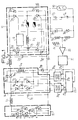
- - la figure 1 est un schéma de principe d'un système d'alimentation haute tension seion l'invention;
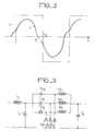
- - la figure 2 est un graphe illustrant le fonctionnement de l'onduleur ; et
- - la figure 3 illustre une variante possible des moyens de commutation formant hacheur.
- - Figure 1 is a block diagram of a high voltage power supply system according to the invention;
- - Figure 2 is a graph illustrating the operation of the inverter; and
- - Figure 3 illustrates a possible variant of the switching means forming a chopper.
Le schéma de la figure 1 représente un système d'alimentation d'une charge 10 qui est ici un tube générateur de rayons X. Ce système se compose essentiellement d'un pont redresseur 11 à diodes, d'un onduleur 12 du type à résonance, alimenté par le pont redresseur 11, de moyens de régulation et de règlage 13 pour stabiliser la tension délivrée à la charge 10 par l'onduleur à une valeur prédéterminée rèblable et de moyens de commutation commandés 14, formant hacheur, interconnectés entre le pont redreseur et l'onduleu. Le pont redresseur 11 est un classique pont de GRAETZ à six diodes D1 -D6 reliées à un réseau de distribution de courant alternatif triphasé 15. La sortie du pont redresseur 11 est reliée à l'entrée d'un quadripâle formant une cellule de filtrage comportant une self L1 en tête et un condensateur C1 en dérivation. Ce quadripôle est monté en cascade avec les moyens 14 formant hacheur, le point commun de la self L1 et du condensateur C1 étant relié à l'anode d'un thyristor Th1, constituant l'élément de commutation principal des moyens 14, lesquels seront décrits en détail plus loin. La sortie des moyens de commutation commandés 14 est connectée er. cascade à l'entrée d'un autre quadripôle formant cellule de filtrage, comportant une self L2 en tête et un condensateur C2 en dérivation. La sortie de ce quadripôle est connectée aux bornes d'alimentation 16,17 de l'onduleur 12. Celui-ci est d'un type connu dit "à résonance" c'est à dire constitué par un montage en pont de quatre thyristors Ty1, Ty2, TY3 et Ty4. Une diagonale du pont est constituée par les bornes d'alimentation 16,17 et reçoit donc une tension continue d'alimentation tandis que l'autre diagonale est constituée par un branchement en séries d'un condensateur C3, d'une self L3 et l'enroulement primaire 18 d'un transformateur élévateur T. Des diodes de récupération Dy1-Dy4 sont respectivement connectées en anti-parallèle aux bornes des thyristors Ty1-Ty4. Un circuit générateur d'impulsions de commande de l'onduleur G pilote d'une part les gachettes de deux thyristors Ty1 et Ty4 appartenant à deux branches différentes du pont pour appliquer la tension d'alimentation au circuit oscillant constitué par le condensateur C3 et les selfs L3 et 18 selon une polarité possible et, d'autre part, les gachettes des deux autres thyristors Ty2, Ty3 pour appliquer la tension d'alimentation au même circuit oscillant, selon l'autre polarité possible.The diagram in FIG. 1 represents a system for supplying a
L'enroulement secondaire 19 du transformateur élévateur T est relié à la charge 10 par l'intermédiaire d'un montage en pont connu formant doubleur de tension et constitué de deux diodes D7, D8 en série et de deux condensateurs C3, C4 en série, la charge 10 étant reliée aux points communs des diodes et condensateurs et l'enroulement secondaire étant relié entre le point commun des deux diodes et le point commun des deux condensateurs. Un diviseur de tension formé de deux résistances R1, R2 en série, branché en parallèle sur la charge 10, constitue le premier élément des moyens de régulation et de règlage 13 mentionnés plus haut. Le point commun des résistances R1 et R2 est relié à une entrée d'un amplificateur différentiel 20 qui reçoit sur son autre entrée une tension de référence réglable par un potentiomètre P1. La sortie de l'amplificateur 20 est reliée à un circuit 21 classique formant générateur d'impulsions de pilotage. Ces impulsions de durée variable assurent la commande du thyristor Th1. Le déclenchement du thyristor est piloté en synchronisme avec chaque front montant d'impulsion tandis que le blocage de ce même thyristor est commandé à partir de chaque front descendant. Pour cela, la sortie du circuit 21 est connectée à l'entrée d'un circuit d'aiguillage 22 (du genre bistable) qui est relié par deux sorties aux entrées de validation 23a, 23b respectives de deux circuits de pilotage 24a, 24b commandant chacun deux thyristors (T1, T'1-T2, T'2 respectivement) du circuit d'extinction 14a du thyristor Th1. Ces circuits de pilotage peuvert comporter notamment des transformateurs d'impulsion à double enroulement secondaire permettant le déclenchement simultané des deux thyristors correspondants, tout en les isolants galvani- quement l'un de l'autre. Chaque circuit de pilotage 24a, 24b comporte une entrée de commande 25a, 25b sensible à un front descendant d'impulsion et reliée à la sortie du circuit 21. Un tel circuit de pilotage élabore donc des impulsions de commande pour les thyristors auxquels il est relié, en synchronisme avec un front descendant d'une impulsion de sortie du circuit 21 et pour autant que son entrée 23 ait reçu un signal de validation du circuit d'aiguillage 22. Ainsi, le thyristor Th1 sera directement déclenché à chaque front montant d'une impulsion délivrée par le générateur 21 et s'éteindra avec le front descendant de cette même impulsion, le circuit d'extinction 14a étant déclenché alternativement par les thyristors T1, T' et T2, T'2. Ce circuit d'extinction comporte principalement un condensateur C5 (dont la charge est commandée par les quatres thyristors T1-T'1, T2-T'2), une self L4 et une diode D9 connectée en anti-parallèle entre l'anode et la cathode du thyristor Th1. La self L4 est en série avec une diode D10 dite "de roue libre" de la cellule de filtrage L2-C2 et l'ensemble est branché en parallèle à l'entrée de ce quadripôle, la self L4 étant reliée à la cathode du thyristor Th1. Les thyristors T et T'2 sont connectés en série ainsi que les thyristors T2 et T'1, ces deux branches étant connectées en parallèle entre l'anode du thyristor Th1 et le point commun de la self L4 et de la diode D10. Le condensateur C5 est branché entre le point commun des thyristors T1, T'2 et le point commun des thyristors T2, T'1. Le condensateur C5 et la diode L4 forment un circuit oscillant calculé pour contrôler la décharge du condensateur C5 pendant un temps suffisant pour annuler le courant du thyristor Th et le maintenir dans cet état pendant un intervalle de temps supérieur à son temps de désarmorçage.The
Le fonctionnement général du système qui vient d'être décrit est le suivant.The general operation of the system which has just been described is as follows.
Le circuit oscillant de l'onduleur, formé par le condensateur C3, la self L3 et l'enroulement primaire 18, à une fréquence de résonance donnée et la fréquence de fonctionnement de l'onduleur, imposée par le générateur G est fixe et choisie légèrement inférieure à cette fréquence de résonance. La figure 2 représente la relation tension-courant dans le circuit oscillant. La tension V a la forme d'une onde rectangulaire puisqu'elle est imposée par les commutations des thyristors. Le courant C est presque sinusoïdal, il s'annule à l'instant t1 et change de signe. Comme les deux thyristors correspondants ne peuvent conduire en inverse, le courant s'écoule par les diodes de récupération associées. A l'instant t2, les deux autres thyristors du pont sont amorcés. L'intervalle T1-T2 correspondant à l'avance du courant par rapport à la tension est choisi supérieur au temps de désamorçage des thyristors. La tension prélévée à l'enroulement secondaire 19 du transformateur est redressée et doublée par le circuit de diodes D7, D8 et condensateurs C3, C4 pour être appliquée au tube générateur de rayons X 10. Les moyens de régulation et de règlage 13 pilotés par la tension aux bornes de la charge permettent de faire varier le rapport cyclique de conduction du thyristor Thl, c'est à dire de faire varier en conséquence la tension d'alimentation de l'onduleur 12, appliquée entre les bornes 16, 17. Selon l'invention, un seul interrupteur statique, le thyristor Thl, permet de compenser les variations du réseau d'alimentation et de maintenir la valeur de la haute tension à la valeur désirée. La fréquence de fonctionnement est élevée, au minimum plusieurs khZ, et la rapidité de réponse du système est grande, très supérieure à celle des systèmes fonctionnant à la fréquence du réseau. Par rapport à un pont de Graetz à thyristors commandés par la phase, le système hacheur présente un meilleur Cos ψ et le filtrage de la tension de sortie est beaucoup plus facile.The oscillating circuit of the inverter, formed by the capacitor C 3 , the choke L 3 and the
Le fonctionnement particulier des moyens de commutation commandés 14 est le suivant. A chaque front montant d'une impulsion délivrée par le circuit 21, le thyristor Th1 est amorcé. Si l'on suppose que le condensateur C5 a été préalablement chargé par la mise en conduction des deux thyristors T1 et T'1, on pourra provoquer l'extinction du thyristor Th1 par la mise en conduction des thyristors T2, T'2, à la fin de l'impulsion délivrée par le circuit 21. Cette mise en conduction des thyristors T2, T'2 sera commandée par le circuit 24b préalablement validé par le circuit d'aiguillage 22. Le condensateur C5 se déchargera donc en commençant par annuler le courant traversant le thyristor Thl, condition de son extinction, puis en s'écoulant par la diode D9, ceci pendant un temps supérieur au temps de désamorçage du thyristor. D'autre part, comme le condensateur C5 et la self L4 définissent un circuit oscillant (calculé pour garantir un temps de décharge du condensateur supérieur au temps de désamorçage du thyristor) la tension va s'inverser aux bornes du condensateur C5 de sorte que celui-ci se trouvera rechargé avec une polarité inverse en vue de la prochaine extinction du thyristor Th1, qui aura lieu cette fois par mise en conduction des thyristors T1, T'1.The particular operation of the controlled switching means 14 is as follows. At each rising edge of a pulse delivered by the
Bien entendu, la structure des moyens de commutation commandés 14 n'est pas limitée aux modes de réalisation de la figure 1. En particulier, lorsque la puissance électrique demandée au système n'est pas trop importante, il devient avantageux d'utiliser un ou plusieurs transistors à la place du thyristor Thl, ce qui simplifie grandement l'agencement de commande du hacheur et permet de fonctionner à une fréquence plus élevée, facilitant encore le filtrage de la tension de sortie. Par ailleurs, on peut à la fois augmenter la puissance disponible et améliorer le filtrage en utilisant un hacheur polyphasé comme illustré à la figure 3 où les circuits de déclenchement et d'extinction n'ont pas été représentés mais découlent avec évidence de ceux de la figure 1. Selon cette variante, le thyristor Th1 est remplacé par trois thyristors Th11, Th12, Th13. Les anodes de ces thyristors sont communes et reliées comme précédemment à la self L1. Leurs cathodes sont respectivement reliées à des selfs L21, L22 et L23 formant avec le condensateur C2 une cellule de filtrage. Chaque self est également associée à sa propre diode dite "de roue libre" D11, D12 et D13. Les trois thyristors sont commandés pour fonctionner à la même fréquence mais déphasés de 2 M3 les uns par rapport aux autres. Tout se passe comme si l'on avait un seul hacheur trois fois plus puissant et fonctionnant à une fréquence triple.Of course, the structure of the controlled switching means 14 is not limited to the embodiments of FIG. 1. In particular, when the electrical power requested from the system is not too great, it becomes advantageous to use one or more several transistors in place of thyristor Th l , which greatly simplifies the control arrangement of the chopper and makes it possible to operate at a higher frequency, further facilitating the filtering of the output voltage. Furthermore, it is possible both to increase the available power and to improve the filtering by using a polyphase chopper as illustrated in FIG. 3 where the triggering and extinction circuits have not been shown but clearly follow from those of the Figure 1. According to this variant, the thyristor Th 1 is replaced by three thyristors Th 11 , Th 12 , Th 13 . The anodes of these thyristors are common and connected as previously at the self L 1 . Their cathodes are respectively connected to inductors L 21 , L 22 and L 23 forming with the capacitor C 2 a filter cell. Each inductor is also associated with its own so-called "freewheeling" diode D 11 , D 12 and D 13 . The three thyristors are controlled to operate at the same frequency but phase-shifted by 2 M 3 relative to each other. Everything happens as if we had a single chopper three times more powerful and operating at a triple frequency.
Dans tous les cas, locsque le système est utilisé en radiologie, il est avantageux de réger le temps de pose par l'intermédiaire de la commande lu hacheur, c'est le mode de commande qui permet de déterminer le début et la fin de l'exposition evec le plus de précision.In all cases, when the system is used in radiology, it is advantageous to adjust the exposure time by means of the chopper command, it is the command mode which makes it possible to determine the beginning and the end of the with the most precision.
Claims (7)
Applications Claiming Priority (2)
| Application Number | Priority Date | Filing Date | Title |
|---|---|---|---|
| FR8221398A FR2538183A1 (en) | 1982-12-21 | 1982-12-21 | HIGH-VOLTAGE POWER SUPPLY SYSTEM OF A LOAD SUCH AS FOR EXAMPLE AN X-RAY GENERATOR |
| FR8221398 | 1982-12-21 |
Publications (1)
| Publication Number | Publication Date |
|---|---|
| EP0112763A1 true EP0112763A1 (en) | 1984-07-04 |
Family
ID=9280323
Family Applications (1)
| Application Number | Title | Priority Date | Filing Date |
|---|---|---|---|
| EP83402407A Withdrawn EP0112763A1 (en) | 1982-12-21 | 1983-12-13 | High voltage power supply system for a load such as an X-ray generator |
Country Status (3)
| Country | Link |
|---|---|
| US (1) | US4652985A (en) |
| EP (1) | EP0112763A1 (en) |
| FR (1) | FR2538183A1 (en) |
Cited By (4)
| Publication number | Priority date | Publication date | Assignee | Title |
|---|---|---|---|---|
| FR2570230A1 (en) * | 1984-09-12 | 1986-03-14 | Trailigaz | DEVICE FORCED SWITCHING OF AN INVERTER AND DEVICE FOR SUPPLYING AN OZONEUR WITH APPLICATION |
| FR2572859A1 (en) * | 1984-11-06 | 1986-05-09 | Electricite De France | Thyristor-based invertor containing a fault protection circuit |
| EP0226256A1 (en) * | 1985-12-18 | 1987-06-24 | Océ-Nederland B.V. | Charging circuit for energy storage capacitors |
| CN102435800A (en) * | 2011-11-07 | 2012-05-02 | 四川中物海通特种电源有限责任公司 | High-voltage pulse generator |
Families Citing this family (12)
| Publication number | Priority date | Publication date | Assignee | Title |
|---|---|---|---|---|
| DE3522569A1 (en) * | 1985-06-24 | 1987-01-02 | Metallgesellschaft Ag | ELECTRICITY POWER SUPPLY |
| NL8601798A (en) * | 1986-07-10 | 1988-02-01 | Hollandse Signaalapparaten Bv | ENERGY CONVERTER. |
| FR2633115B1 (en) * | 1988-06-17 | 1993-02-12 | Gen Electric Cgr | STABILIZED POWER SUPPLY WITH REDUCED ROPE RATE |
| US4965709A (en) * | 1989-09-25 | 1990-10-23 | General Electric Company | Switching converter with pseudo-resonant DC link |
| FR2666000B1 (en) * | 1990-08-14 | 1996-09-13 | Gen Electric Cgr | DEVICE FOR SUPPLYING AND REGULATING THE CURRENT OF A CATHODE FILAMENT OF A RADIOGENIC TUBE. |
| US5208741A (en) * | 1991-03-28 | 1993-05-04 | General Electric Company | Chopper circuit for dynamic braking in an electric power conversion system |
| US5773799A (en) * | 1996-04-01 | 1998-06-30 | Gas Research Institute | High-frequency induction heating power supply |
| US5908575A (en) * | 1997-05-16 | 1999-06-01 | Gas Research Institute | Method of inductively fusion joining plastic pipes |
| DE10332417A1 (en) * | 2003-07-16 | 2005-02-24 | Sirona Dental Systems Gmbh | Method for controlling an X-ray device and X-ray device |
| US8179701B2 (en) * | 2009-01-09 | 2012-05-15 | Yaskawa America, Inc. | Variable frequency drive soft charge circuit |
| US8605469B2 (en) | 2012-02-13 | 2013-12-10 | Yasakawa America, Inc. | AC side soft charge circuit for variable frequency drives |
| CN114666960B (en) * | 2022-03-28 | 2024-07-19 | 珠海市睿影科技有限公司 | X-ray machine high voltage generator control circuit and X-ray machine |
Citations (4)
| Publication number | Priority date | Publication date | Assignee | Title |
|---|---|---|---|---|
| FR2293825A1 (en) * | 1974-12-03 | 1976-07-02 | Siemens Ag | SWITCHING DEVICE FOR STATIC CONVERTER INTENDED FOR POWERING ELECTRIC MOTORS |
| US4024453A (en) * | 1976-08-26 | 1977-05-17 | General Motors Corporation | Inverter for supplying a regulated voltage |
| FR2427728A1 (en) * | 1978-06-02 | 1979-12-28 | Tocco Stel | Variable-power static inverter - has bridge contg. four thyristors controlled by oscillator of frequency two thirds that of inverter |
| GB2085677A (en) * | 1980-09-17 | 1982-04-28 | Gen Motors Corp | Multiple phase choppers |
Family Cites Families (16)
| Publication number | Priority date | Publication date | Assignee | Title |
|---|---|---|---|---|
| US3510753A (en) * | 1967-12-04 | 1970-05-05 | Rowan Controller | Ripple eliminator for pulsating unidirectional current power supply |
| BE791943A (en) * | 1972-02-18 | 1973-03-16 | Telecomunicazioni Soc It | VOLTAGE AND / OR CURRENT REGULATOR |
| US3821630A (en) * | 1973-08-02 | 1974-06-28 | Gen Electric | Commutation failure detection and control for scr inverters |
| US3930193A (en) * | 1973-08-02 | 1975-12-30 | Gen Electric | SCR inverter systems |
| CH593585A5 (en) * | 1973-12-13 | 1977-12-15 | Danfoss As | |
| US4042871A (en) * | 1975-11-14 | 1977-08-16 | Ecc Corporation | Conversion system with overcurrent protection and start-up circuitry |
| US4074345A (en) * | 1976-11-02 | 1978-02-14 | Ackermann Walter J | Electronic power supply |
| JPS5426420A (en) * | 1977-07-28 | 1979-02-28 | Kin Tokai | Accac converter circuit |
| DE2802424A1 (en) * | 1978-01-20 | 1979-07-26 | Siemens Ag | ROYAL DIAGNOSTIC GENERATOR WITH AN INVERTER FEEDING ITS HIGH VOLTAGE TRANSFORMER |
| FR2421430A1 (en) * | 1978-03-29 | 1979-10-26 | Peugeot | DEVICE TO SIMULATE THE OPERATION OF AN ACCUMULATOR BATTERY, IN PARTICULAR A TRACTION BATTERY FOR AN ELECTRIC VEHICLE |
| US4277728A (en) * | 1978-05-08 | 1981-07-07 | Stevens Luminoptics | Power supply for a high intensity discharge or fluorescent lamp |
| US4220989A (en) * | 1978-12-08 | 1980-09-02 | Perilstein Fred M | Polyphase variable frequency inverter with output voltage control |
| DE2908767A1 (en) * | 1979-03-06 | 1980-09-18 | Siemens Ag | X-RAY DIAGNOSTIC GENERATOR WITH AN INVERTER UPstream of the HIGH VOLTAGE TRANSFORMER |
| US4293904A (en) * | 1979-11-21 | 1981-10-06 | The United States Of America As Represented By The Secretary Of The Navy | Power frequency converter |
| US4350891A (en) * | 1980-07-14 | 1982-09-21 | Pennwalt Corporation | Low ripple regulated X-ray tube power supply |
| SE426121B (en) * | 1981-04-28 | 1982-12-06 | Ericsson Telefon Ab L M | HOGS MONEY CONVERTER |
-
1982
- 1982-12-21 FR FR8221398A patent/FR2538183A1/en active Granted
-
1983
- 1983-12-13 EP EP83402407A patent/EP0112763A1/en not_active Withdrawn
- 1983-12-20 US US06/563,432 patent/US4652985A/en not_active Expired - Fee Related
Patent Citations (4)
| Publication number | Priority date | Publication date | Assignee | Title |
|---|---|---|---|---|
| FR2293825A1 (en) * | 1974-12-03 | 1976-07-02 | Siemens Ag | SWITCHING DEVICE FOR STATIC CONVERTER INTENDED FOR POWERING ELECTRIC MOTORS |
| US4024453A (en) * | 1976-08-26 | 1977-05-17 | General Motors Corporation | Inverter for supplying a regulated voltage |
| FR2427728A1 (en) * | 1978-06-02 | 1979-12-28 | Tocco Stel | Variable-power static inverter - has bridge contg. four thyristors controlled by oscillator of frequency two thirds that of inverter |
| GB2085677A (en) * | 1980-09-17 | 1982-04-28 | Gen Motors Corp | Multiple phase choppers |
Cited By (6)
| Publication number | Priority date | Publication date | Assignee | Title |
|---|---|---|---|---|
| FR2570230A1 (en) * | 1984-09-12 | 1986-03-14 | Trailigaz | DEVICE FORCED SWITCHING OF AN INVERTER AND DEVICE FOR SUPPLYING AN OZONEUR WITH APPLICATION |
| EP0176425A1 (en) * | 1984-09-12 | 1986-04-02 | Trailigaz | Forced-commutation device for an inverter and supply device of an ozonizer therefor |
| FR2572859A1 (en) * | 1984-11-06 | 1986-05-09 | Electricite De France | Thyristor-based invertor containing a fault protection circuit |
| EP0226256A1 (en) * | 1985-12-18 | 1987-06-24 | Océ-Nederland B.V. | Charging circuit for energy storage capacitors |
| CN102435800A (en) * | 2011-11-07 | 2012-05-02 | 四川中物海通特种电源有限责任公司 | High-voltage pulse generator |
| CN102435800B (en) * | 2011-11-07 | 2014-06-11 | 四川中物海通特种电源有限责任公司 | High-voltage pulse generator |
Also Published As
| Publication number | Publication date |
|---|---|
| US4652985A (en) | 1987-03-24 |
| FR2538183A1 (en) | 1984-06-22 |
| FR2538183B1 (en) | 1985-04-05 |
Similar Documents
| Publication | Publication Date | Title |
|---|---|---|
| EP0112763A1 (en) | High voltage power supply system for a load such as an X-ray generator | |
| WO2005109615A2 (en) | Anharmonic low-current ac-dc converter | |
| FR2606227A1 (en) | CONTROL DEVICE FOR CONTINUOUS / CONTINUOUS RESONANT CONVERTER | |
| FR2568715A1 (en) | DEVICE FOR CONTROLLING AN ELECTROMAGNET COIL AND ELECTRIC SWITCHING APPARATUS PROVIDED WITH SUCH A DEVICE | |
| EP0353112A1 (en) | DC/DC "Cük" converter and mains supply with direct conversion realised by means of such a converter | |
| FR2606228A1 (en) | DEVICE FOR CONTROLLING THE OUTPUT OF A HIGH FREQUENCY POWER SUPPLY UNIT | |
| FR2607996A1 (en) | METHOD AND DEVICE FOR IGNITION OF DISCHARGE LAMPS | |
| FR2663170A1 (en) | METHOD FOR CONTROLLING A CUTTING REGULATOR AND DEVICE FOR IMPLEMENTING SAID METHOD. | |
| EP0903829B1 (en) | Filter device having a control circuit and electric apparatus using such device | |
| EP0550336A1 (en) | Method and electric supply for a plasma torch | |
| EP0267252B1 (en) | Frequency converter for the stabilized supply of asynchronous motors | |
| EP0176413B1 (en) | Switched mode dc-dc converter | |
| EP0616415A1 (en) | Control device for the oscillating circuit of a voltage inverter with quasi-resonant operation and PWM regulation | |
| EP1586157B1 (en) | Supply generator for an oscillating circuit, particularly for an induction cooking hob | |
| FR2756678A1 (en) | ELECTRIC ARC GENERATOR WITH INVERTER AND THREE-PHASE POWER SUPPLY | |
| EP0143048B1 (en) | Dc-to-dc converter with switched storage inductance | |
| EP0507663B1 (en) | Method and apparatus for attenuating the effect of conducted radiointerference on the polyphase AC network | |
| EP2182622B1 (en) | Circuit for power factor correction | |
| FR2497421A1 (en) | Non-inverting variable ratio DC=DC switching regulator - uses series switch driving an LC circuit to step up input voltage and shunt switch to lower output voltage | |
| CA2869170C (en) | Current generator and method for generating current pulses | |
| EP0538102B1 (en) | Power supply device for ozonizer | |
| EP0405653B1 (en) | Electric energy power converter of which commutation is aided by an active control of the supplying voltage of the voltage inverter circuit | |
| FR2575010A1 (en) | Power unit for electrical discharge pulsed laser | |
| EP0538103B1 (en) | Improved power supply device for ozonizer | |
| FR2820560A1 (en) | FEEDING DEVICE |
Legal Events
| Date | Code | Title | Description |
|---|---|---|---|
| PUAI | Public reference made under article 153(3) epc to a published international application that has entered the european phase |
Free format text: ORIGINAL CODE: 0009012 |
|
| AK | Designated contracting states |
Designated state(s): DE GB NL SE |
|
| 17P | Request for examination filed |
Effective date: 19841215 |
|
| STAA | Information on the status of an ep patent application or granted ep patent |
Free format text: STATUS: THE APPLICATION IS DEEMED TO BE WITHDRAWN |
|
| 18D | Application deemed to be withdrawn |
Effective date: 19880110 |
|
| RIN1 | Information on inventor provided before grant (corrected) |
Inventor name: BOUGLE, JEAN |