EP0112717B1 - Continuous speech recognition apparatus - Google Patents
Continuous speech recognition apparatus Download PDFInfo
- Publication number
- EP0112717B1 EP0112717B1 EP83307796A EP83307796A EP0112717B1 EP 0112717 B1 EP0112717 B1 EP 0112717B1 EP 83307796 A EP83307796 A EP 83307796A EP 83307796 A EP83307796 A EP 83307796A EP 0112717 B1 EP0112717 B1 EP 0112717B1
- Authority
- EP
- European Patent Office
- Prior art keywords
- data
- speech
- similarity
- frame
- interval
- Prior art date
- Legal status (The legal status is an assumption and is not a legal conclusion. Google has not performed a legal analysis and makes no representation as to the accuracy of the status listed.)
- Expired
Links
Images




Classifications
-
- G—PHYSICS
- G10—MUSICAL INSTRUMENTS; ACOUSTICS
- G10L—SPEECH ANALYSIS TECHNIQUES OR SPEECH SYNTHESIS; SPEECH RECOGNITION; SPEECH OR VOICE PROCESSING TECHNIQUES; SPEECH OR AUDIO CODING OR DECODING
- G10L15/00—Speech recognition
Definitions
- the present invention relates to a continuous speech recognition apparatus to recognize an utterance or speech generated continuously.
- the reference patterns representative of respective words are used and by calculating the similarity between the feature patterns indicative of the input speech and the reference patterns, the input speech is recognized on a word unit basis; therefore, this type of apparatus is hardly affected by coarticulation between successive speech segments.
- the word identification method in this recognition apparatus is mainly divided into two methods: a first method being attained by detecting the word interval of the input speech and identifying the words in this word interval; and a second method being attained by detecting words which would possibly exist in the generation interval of the input speech without detecting the word interval.
- the word interval is determined by sequentially extracting the feature parameters of, e.g.
- reference patterns each having feature parameters of a plurality of frames are used for each word in the input speech, and the distances between the feature parameters of a plurality of frames of the input speech and the reference patterns are obtained for every frame, thereby determining the word which gives the minimum distance.
- the distances between the feature patterns of the input speech and the reference patterns are obtained by, e.g. a dynamic programming method. In this way all of the word series that can exist in the whole speech interval are detected and the word series in which the sum of the distances relating to the words is minimum among these series of words is detected, thereby recognizing the input speech.
- This word identification method is effective in the case where speakers are limited and where the word identification can be executed using a small number of reference patterns.
- the speech pattern of each word largely differs in dependence upon the speakers; therefore, it is necessary to prepare a great amount of reference patterns for each word in order to process the speech information from unspecified speakers. It is of course actually impossible to prepare the reference patterns of the number corresponding to the number of unspecified speakers and, accordingly, it is impossible to suitably recognize the speech from all of the unspecified speakers.
- an apparatus for recognizing the occurrence of a command word within continuous speech in which feature signals are derived from the input speech and part of the features are selected as feature subset masks depending upon whether or not the feature is found to generally occur during a given period of time.
- the feature subsets are compared with incoming features subsets to determine the time interval or boundary of command word candidates.
- a continuous speech recognition apparatus comprising speech signal generating means for generating a speech signal in response to input speech; acoustic analyzing means for extracting rough and detail feature parameter data of the speech signal from said speech signal generating means for each frame; said detail feature parameter data including N parameters which correspond to speech signal components respectively having N frequency bands which form the frequency band of said speech signal; speech interval detection means for detecting the speech interval of the input speech; first and second memory means in which rough and detail reference pattern data representative of a plurality of speech units are stored; data generating means for detecting the subperiods where the speech units exist in said speech intervals on the basis of the feature parameter data from said acoustic analyzing means, and for generating the speech unit data representative of the speech unit in each subperiod and the similarity between said speech unit data and said detail reference pattern data; and recognition means for detecting the sum of similarity data relating to subperiods in each subperiod series constituting said speech interval, and detecting maximum one of the sums of
- a continuous speech recognition apparatus comprising an acoustic analyzer to extract rough and detail feature parameter data of input speech for every frame; a speech interval detector; a first data generation circuit which calculates the similarity between the rough feature parameter data of a predetermined number of frames and the rough reference pattern data and generates the frame data representative of the frame position of the rough feature parameter which has given the similarity of not lower than a preset value together with the reference pattern indicative data corresponding to the rough reference pattern data which has given the similarity of not lower than this preset value; a second data generation circuit which detects a plurality of subperiods to be obtained by dividing a speech interval in accordance with that frame data and calculates the similarity between the detail feature pattern data corresponding to each subperiod and the detail reference pattern data designated by the reference pattern indicative data corresponding to this subperiod, thereby generating each subperiod data, similarity data and reference pattern indicative data relating to this subperiod data; and a recognition circuit which detects the subperio
- the subperiod where the minimum unit of the speech to be recognized exists is schematically detected using the rough feature parameters and the similarity with respect to each speech unit in the interval thus detected is calculated, thereby determining the effective word series in the speech interval; therefore, the speech can be efficiently and highly accurately recognized.
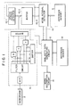
- Fig. 1 is a block diagram showing a continuous speech recognition apparatus according to one embodiment of the present invention.
- This continuous speech recognition apparatus comprises a microphone 2 to generate an electrical speech signal in accordance with input speeches; an acoustic analyzer 4 to extract rough and detail feature parameter data from the speech signal supplied from this microphone 2 for every frame; and reference memories 6 and 8 in which rough and detail reference pattern data are stored, respectively.
- the acoustic analyzer 4 includes an A/D converter to convert the speech signal from the microphone 2 into a digital signal at every 0.1 msec, for example, N band-pass filters which commonly receive the digital signal from this A/D converter and generate the output signals having the frequency bands to be obtained by dividing the frequency band of the speech signal into N channels (where, N is an integer of, e.g. 16 to 32), and N acoustic energy level detectors respectively connected to the band-pass filters.
- the feature parameter data including N parameters corresponding to the speech signal components having N frequency bands, respectively is extracted as a part of the detail feature pattern data from this acoustic analyzer 4 and is stored in the buffer memory at every 10 msec, for example.
- the feature parameter data including M parameters corresponding to M speech signal components having the frequency bands,-respectively, to be obtained by dividing the frequency band of the speech signal into M channels is extracted as a part of the rough feature pattern data from the acoustic analyzer 4 and is stored in the buffer memory at every 10 msec.
- the buffer memories to store part of the rough and detail feature pattern data are each constituted so as to have the memory capacity in which one-frame feature parameter data can be stored.
- the reference memory 6 stores a plurality of reference pattern data, each schematically representing the front portion of each of a plurality of words to be registered, and each having F1 frames of feature parameter data which are each formed of M parameters.
- the reference memory 8 stores a plurality of reference pattern data, each representing the above-mentioned plurality of words in detail, and each having F2 frames of reference parameter data which are each formed of N parameters.
- this recognition apparatus includes a probable-word-interval detection circuit 10 which fetches the rough feature parameter data from the acoustic analyzer 4 at every 10 msec, for example, and calculates the similarity between the rough feature pattern data constituted by the rough feature parameter data of F1 frames and all of the rough reference pattern data stored in the reference memory 6.
- This probable-word-interval detection circuit 10 comprises a speech interval detector 10-1 to detect the speech interval on the basis of the rough feature parameter data from the acoustic analyzer 4; a buffer memory 10-2 to sequentially store the rough feature parameter data from the acoustic analyzer 4 and consequently store the rough feature pattern data constituted by the rough feature parameter data of F1 frames; and a probable-word-interval detector 10-3 which calculates the similarity between the rough feature pattern data in this buffer memory 10-2 and rough reference pattern data in the reference memory 6 and generates, whenever the similarity of not lower than a preset value is obtained, the address data corresponding to the rough reference pattern data which gives this similarity and the frame data indicative of the position of the head frame of the rough feature pattern data which gives this similarity.
- This word interval detector 10-3 is constituted by, for example, a similarity calculation circuit; a counter circuit which is reset in response to the output signal indicating the start of the speech interval from the above-mentioned speech interval detector 10-1, and thereafter which counts the number of times of the calculations executed in the above-mentioned similarity calculation circuit; an address converter to convert the address data supplied to the reference memory 6 into the corresponding address data; and a control circuit which supplies the address data from the address converter to the outside whenever it is detected that the similarity of not lower than a preset value is obtained from the similarity calculation circuit, and at the same time which supplies the count data from the above-mentioned counter circuit as a frame data to the outside although these components are not shown in Fig. 1.
- This control circuit further supplies the output signal from the counter circuit to the outside even when the signal indicative of the end of the speech interval from the speech interval detector 10-1 is detected.
- This similarity data generating circuit 12 calculates the similarity between the detail feature pattern data from the acoustic analyzer 4 in the probable word-intervals determined by the frame data and the detail reference pattern data read out from the memory location in the reference memory 8 designated by the address data from the interval detection circuit 10. Then the circuit 12 supplies the interval data relating to the probable word-intervals, word data in the respective probable word-intervals and similarity data calculated with respect to these word data to a word recognition circuit 14.
- This word recognition circuit 14 detects all combinations of the probable word-interval or intervals constituting one speech interval; detects the sum of the similarity data relating to the probable word-intervals of each combination; and extracts the word series represented by the combination of probable word-intervals of which the above-mentioned sum of the similarity data becomes maximum as effective word data.
- the similarity data generating circuit 12 includes a frame register 20 and an address register 22 to sequentially store the frame data and address data from the interval detection circuit 10, respectively; a memory 24 to sequentially store the detail feature parameter data from the acoustic analyzer 4; an interval setting circuit 26 to set the word interval on the basis of the two frame data from the frame register 20; a re-sampling pattern generator 28 to take the detail feature parameter data read out from the memory 24 in accordance with the frame pattern corresponding to the interval data from this interval setting circuit 26; and a pattern register 30 to store the detail feature parameter data of F2 frames supplied from the memory 24 through this pattern generator 28.
- the similarity data generating circuit 12 further includes a similarity calculator 32 to calculate the similarity between the detail feature pattern data stored in the pattern register 30 and the corresponding reference pattern data read out from the memory 8; a maximum detector 34 to detect the maximum similarity from this similarity calculator 32; and a register 36 to sequentially store the similarity data from this maximum detector 34, front and rear frame data from the frame register 20, and address data from the address register 22.
- a control circuit 38 also controls the frame register 20, address register 22 and memory 24 in accordance with the front and rear frame data from the frame register 20.
- the similarity calculation in this embodiment can be carried out in accordance with multiple similarity calculation method disclosed in USP 3,688,267 or mixed similarity calculation method disclosed in USP 3,906,446.
- the speech having the acoustic power characteristic as shown in Fig. 3A is supplied to the microphone 2.
- This speech is converted into an electrical speech signal by this microphone 2, it is supplied to the acoustic analyzer 4.
- This acoustic analyzer 4 supplies the rough and detail feature parameter data in accordance with the input speech signal to the buffer 10-2 and memory 24, respectively, for every frame.
- the speech interval detector 10-1 detects the speech interval to be determined by the time point when it is detected that the rough feature parameter data from this acoustic analyzer 4 becomes a value not lower than a preset value and by the time point when it is detected that this rough feature parameter data becomes and is kept smaller than a.preset value for a predetermined period of time.
- the probable-word-interval detector 10-3 starts calculating the similarity between the rough feature pattern data in the buffer 10-2 and the rough reference pattern data in the reference memory 6 in response to the output signal indicative of the start of the speech interval from the speech interval detector 10-1.
- This similarity calculation processing to each rough feature pattern data in the buffer 10-2 is executed at every 10 msec, for example.
- this word-interval detector 10-3 supplies the frame data with respect to the frame position of the head frame of the rough characteristic pattern data in the buffer 10-2 which gives this similarity, and the address data representative of the memory location in the reference memory 8 in which the detail reference pattern data corresponding to the rough reference pattern data in the reference memory 6 which gives this similarity is stored to the similarity data generating circuit 10.
- the above-described operations are repeatedly executed until the speech signal is terminated.
- each similarity to words [X] and [Y] exceeds the preset value in the timings TS and T1 and in the timing T2, respectively, as shown in Figs. 3B and 3C.
- the word [X] may be started at the respective timings TS and T1
- the word [Y] may be started at the timing T2.
- the word-interval detector 10-3 generates frame data FR1 corresponding to the timing TS and address data X1 corresponding to word [Y], then generates frame data FR2 corresponding to the timing T2 and address data Y1 corresponding to word [Y].
- the control circuit 38 in the similarity data generating circuit 12 sets the frame register 20, address register 22 and memory 24 into the readout mode in response to the output signal indicative of the termination of the speech signal from the interval detector 10-1. Thereafter this control circuit 38 permits the frame register 20 to supply the frame data FR1 and FR2 to the interval setting circuit 26 and allows the address register 22 to supply the address data X1 to the reference memory 8.
- the circuit 38 further sequentially sends the readout address signals corresponding to the frame data FR1 and FR2 to the memory 24 and reads out the detail feature parameter data from the corresponding frame locations of the memory 24 for every frame.
- the interval setting circuit 26 supplies the output signal in response to the interval SW1 to the re-sampling pattern generator 28 in accordance with the frame data FR1 and FR2.
- the re-sampling pattern generator 28 sequentially supplies the detail feature parameter data of F2 frames in predetermined frame positions among the detail feature parameter data of a plurality of frames which are read out from the memory 24 to the pattern register 30.
- the detail feature pattern data of N channels x F2 frames is stored in this pattern register 30 and the similarity with the reference pattern data read out from the memory location in the memory 8 which is designated by the address data X1 is calculated by the similarity calculator 32.
- This similarity data together with the frame data FR1 and FR2 and address data X1 is stored in the register 36.
- the maximum detector 34 extracts, as an effective similarity data, the maximum one of the similarity data obtained by the similarity calculator 32 with respect to these different words in the same word-interval.
- the control circuit 38 then sends a first control signal to the frame register 20 and permits this frame register 20 to generate the frame data FR3 from the second output port in place of the frame data FR2. Due to this the interval setting circuit 26 supplies the output signal in response to the interval XW2 to the re-sampling pattern generator 28.
- This re-sampling pattern generator 28 selectively supplies the detail feature parameter data of F2 frames among the detail feature parameter data which are sequentially read out from the frame positions corresponding to the interval XW2 in the memory 24 to the pattern register 30.
- the similarity between the feature pattern data in this pattern register 30 and the reference pattern data read out from the memory location designated by the address data X1 in the reference memory 8 is calculated. This similarity data is stored in the register 36 together with the frame data FR1 and FR3 and address data X1.
- the control circuit 38 then sends the first control signal to the frame register 20 and allows the frame register 20 to generate the frame data FRE from the second output port in place of the frame data FR3. Due to this, the interval setting circuit 26 supplies the output signal corresponding to the interval XW3 to the re-sampling pattern generator 28. Thereafter the same operations as described before are executed, so that the similarity data with respect to the interval XW3, frame data FR1 and FRE, and address data X1 are stored in the register 36.
- control circuit 38 sends the first and second control signals to the frame register 20 and permits the frame register 20 to generate the frame data FR2 and FR3 from the first and second output ports in place of the frame data FR1 and FRE, respectively. Due to this, the interval setting circuit 26 supplies the output signal in response to the interval YW1 to the re-sampling pattern generator 28. In this case, the re-sampling pattern generator 28 selects the detail feature parameter data of F2 frames among the detail feature parameter data to be sequentially read out from the frame positions corresponding to the interval YW1 in the memory 24 and supplies to the pattern register 30.
- the similarity between the feature pattern data in this pattern register 30 and the reference pattern data read out from the memory location designated by the address data Y1 in the reference memory 8 is calculated.
- This similarity data is stored in the register 36 together with the frame data FR2 and FR3 are address data Y1.
- control circuit 38 sends the first control signal to the frame register 20 and allows this frame register 20 to generate the frame data FRE from the second output port in place of the frame data FR3. Thereafter the same operations as described before are executed, so that the similarity data with respect to the interval YW2, frame data FR2 and FRE, and address data Y1 are stored in the register 36.
- the control circuit 38 sends the first and second control signals to the frame register 20 and permits this frame register 20 to generate the frame data FR3 and FRE from the first and second output ports in place of the frame data FR2 and FRE.
- the interval setting circuit 26 supplies the output signal in accordance with the interval XW4 to the re-sampling pattern generator 28, thereby storing the detail feature parameter data of F2 frames in the frame positions corresponding to the interval XW4 in the memory 24 in the pattern register 30.
- the similarity between the feature pattern data in this pattern register 30 and the reference pattern data read out from the memory location designated by the address data X1 in the reference memory 8 is calculated. This similarity data is stored in the register 36 together with the frame data FR3 and FRE and address data X1.
- the two frame data indicative of the frame interval, similarity data, and address data are stored in the memory locations ML1 to ML6 in the register 36, respectively, in such a manner as described above.
- the individual data in these memory locations ML1 to ML6 represents the six word-intervals XW1 to XW4, YW1 and YW2 in the speech interval, and the similarity and address data with respect to those word-intervals.
- the word recognition circuit 14 creates all combinations in the frame intervals constituting the speech interval on the basis of the frame data in the register 36. For instance, in this example described hereinabove, the frame intervals XW1, YW1 and XW4; frame intervals XW1 and YW2; frame intervals XW2 and XW4; and frame interval XW3 cooperatively or solely constitute the probable speech intervals S11 to S14, respectively.
- the word recognition circuit 14 calculates the sum of the similarity data relating to the respective frame interval or intervals among the speech intervals SI1 to S14 and recognizes, as a series of effective words, a series of words determined by one of the speech intervals SI1 to SI4 having the maximum sum of similarity data.
- Fig. 7 shows an example of detail feature parameter data sequentially generated from the acoustic analyzer 4 and stored in the detail feature pattern memory 24.
- the detail feature parameter data correspond to a speech signal representing "0, 2, 8, 7" (pronounced as “[zero], [ni], [hatfi], [nana]” in Japanese way)".
- the size of each black circle indicates the intensity of acoustic energy.
- each detail feature parameter data includes 16 parameters, and each of rough feature parameter data may be obtained by dividing 16 parameters into four groups.
- head frame positions of the feature pattern data representing "0", "2", “8” and “7” may be detected by sequentially calculating the similarity between the rough feature pattern data and the reference pattern data.
- Detail feature parameter data are selectively extracted from the sequence of feature parameter data in each word interval defined by the head frame positions.
- Figs. 8A to 8D show detail feature pattern data obtained by re-sampling the feature parameter data in respective word intervals corresponding to "0", "2", “8” and “7".
- the similarity between each of the detail feature pattern data and each of the detail reference pattern data is sequentially calculated so that word data representing "0", "2", “8” and “7” can be detected, and stored together with the word interval data and the similarity data.
- word data, word interval data and similarity data input may be recognized.
- the present invention has been described in the above with respect to one embodiment, the invention is not limited to only this embodiment.
- the rough feature parameter data from the acoustic analyzer 4 are sequentially stored in the buffer 10-2 for every one frame in the above-described embodiment, it is for example possible to store these rough feature parameter data in the buffer 10-2 for every other frame using a logical control circuit which is ordinarily well known.
- the rough reference pattern data indicative of the front portion of the detailed reference pattern of each word are stored in the reference memory 6, it is possible to store the rough reference pattern data representative of the rear portion or central portion of the detailed reference pattern of each word in place of that data in this reference memory 6.
- the frame data to be generated from the . probable-word-interval detector 10-3 represents the rear end or central frame position of the corresponding feature pattern data; therefore, in order to determine the word-interval data, the data processing should be changed accordingly.
- words are used as a speech segment unit of the input speech to be recognized; however, it may be possible to recognize the input speech for every syllable, clause, or other speech segment unit.
Landscapes
- Engineering & Computer Science (AREA)
- Computational Linguistics (AREA)
- Health & Medical Sciences (AREA)
- Audiology, Speech & Language Pathology (AREA)
- Human Computer Interaction (AREA)
- Physics & Mathematics (AREA)
- Acoustics & Sound (AREA)
- Multimedia (AREA)
- Compression, Expansion, Code Conversion, And Decoders (AREA)
- Telephonic Communication Services (AREA)
- Measurement Of Mechanical Vibrations Or Ultrasonic Waves (AREA)
Abstract
Description
- The present invention relates to a continuous speech recognition apparatus to recognize an utterance or speech generated continuously.
- In word processors and audio typewriters which handle the input information as speech, it is important to recognize efficiently and highly reliably the speech which is continuously and naturally generated. In R. Schwartz and J. Makhoul: "Where the Phonemes Are: Dealing with Ambiguity in Acoustic-Phonetic Recognition", IEEE Trans. ASSP, Vol. ASSP-23, No. 1, pp. 50-53, 1975 a continuous speech recognition apparatus has been proposed which recognizes the input speech by first converting feature parameter sequence of the input speech into a series of phonemic symbols, i.e. into the so-called segment lattice using a minimum unit of the speech to be recognized as a speech segment unit. However, in the speech to be continuously generated, there may be a case where a certain speech segment is coarticulated with the speech segments to be generated before and after the segment, so that even in case of the same speech segment, it would have various different kinds of feature parameters. Due to this, it is difficult to convert the input speech into phonemic symbols with high degree of accuracy.
- In addition, in L.R. Rabiner and M.R. Sambur: "Some Preliminary Experiments in the Recognition of Connected Digits", IEEE Trans. ASSP, Vol. ASSP-24, No. 2, pp. 170-182, 1976, and in T.K. Vintsyuk: "Element Wise Recognition of Continuous Speech Composed of Words from a Specified Dictionary", Kibernetika (Cybernetics), No. 2, pp. 133-143, 1971 a continuous speech recognition apparatus has been proposed which identifies words from the feature parameter sequence of the input speech using the minimum unit of the input speech to be recognized as a word unit, thereby recognizing a series of these identified words as a sentence. In this recognition apparatus, the reference patterns representative of respective words are used and by calculating the similarity between the feature patterns indicative of the input speech and the reference patterns, the input speech is recognized on a word unit basis; therefore, this type of apparatus is hardly affected by coarticulation between successive speech segments. Furthermore, the word identification method in this recognition apparatus is mainly divided into two methods: a first method being attained by detecting the word interval of the input speech and identifying the words in this word interval; and a second method being attained by detecting words which would possibly exist in the generation interval of the input speech without detecting the word interval. In the former word identification method, the word interval is determined by sequentially extracting the feature parameters of, e.g. the acoustic powers or acoustic spectra of the input speech and by detecting the maximal or minimal point of changes in these feature parameters. However, in the case where, for example, "I (ai)" and "eat (i:t)" are continuously generated so that when "I eat (ai:t)" is formed, there is a problem such that it is impossible to correctly detect the word intervals in this speech.
- In addition, in the latter word identification method, reference patterns each having feature parameters of a plurality of frames are used for each word in the input speech, and the distances between the feature parameters of a plurality of frames of the input speech and the reference patterns are obtained for every frame, thereby determining the word which gives the minimum distance. In this case, the distances between the feature patterns of the input speech and the reference patterns are obtained by, e.g. a dynamic programming method. In this way all of the word series that can exist in the whole speech interval are detected and the word series in which the sum of the distances relating to the words is minimum among these series of words is detected, thereby recognizing the input speech.
- This word identification method is effective in the case where speakers are limited and where the word identification can be executed using a small number of reference patterns. However, for unspecified speakers, the speech pattern of each word largely differs in dependence upon the speakers; therefore, it is necessary to prepare a great amount of reference patterns for each word in order to process the speech information from unspecified speakers. It is of course actually impossible to prepare the reference patterns of the number corresponding to the number of unspecified speakers and, accordingly, it is impossible to suitably recognize the speech from all of the unspecified speakers.
- To cope with such a drawback, recently, an idea has been considered in L.R. Rabiner and C.E. Schmidt: "Application of Dynamic Time Warping to Connected Digit Recognition", IEEE Trans. ASSP, Vol. ASSP-28, No. 4, pp. 377-388, 1980 whereby a small limited number of reference patterns are used for each word and the speech information from unspecified speakers is processed by applying the clustering technique. In this case, however, the rate of correct recognition for a series of words will be remarkably reduced and furthermore it is necessary to calculate the distances between the reference patterns and the feature patterns of the input speech for every frame, causing the total amount of calculations to be extremely increased. Thus, it is very difficult to recognize efficiently and highly reliably speech which is continuously generated.
- Also, in US Patent 4107460, an apparatus for recognizing the occurrence of a command word within continuous speech is disclosed in which feature signals are derived from the input speech and part of the features are selected as feature subset masks depending upon whether or not the feature is found to generally occur during a given period of time. The feature subsets are compared with incoming features subsets to determine the time interval or boundary of command word candidates.
- Also, in 8180 IEEE Transactions on Pattern Analysis and Machine Intelligence, Volume PAM 1-2 (1980) March, No. 2, New York, USA, between pp. 136 and 148 in an article entitled Use of Fuzzy Algorithms for Phonetic and Phonemic Labeling of Continuous Speech (R. De Mori and P. Laface) gross feature parameters are described by languages or signals in accordance with rewriting rules and are then used to segment continuous speech into syllabic units by a syntactic recognition algorithm.
- It is an object of the present invention to provide a continuous speech recognition apparatus which can efficiently and highly accurately recognize the speech continuously generated by unspecified speakers.
- According to the invention, there is provided a continuous speech recognition apparatus comprising speech signal generating means for generating a speech signal in response to input speech; acoustic analyzing means for extracting rough and detail feature parameter data of the speech signal from said speech signal generating means for each frame; said detail feature parameter data including N parameters which correspond to speech signal components respectively having N frequency bands which form the frequency band of said speech signal; speech interval detection means for detecting the speech interval of the input speech; first and second memory means in which rough and detail reference pattern data representative of a plurality of speech units are stored; data generating means for detecting the subperiods where the speech units exist in said speech intervals on the basis of the feature parameter data from said acoustic analyzing means, and for generating the speech unit data representative of the speech unit in each subperiod and the similarity between said speech unit data and said detail reference pattern data; and recognition means for detecting the sum of similarity data relating to subperiods in each subperiod series constituting said speech interval, and detecting maximum one of the sums of similarity data on the basis of the output data from said data generation means, thereby recognizing the speech unit data having said detected maximum sum of similarity data as the input speech, characterized in that said rough feature parameter data includes M parameters, M being less than N (M < N), which M parameters correspond to speech signal components respectively having M frequency bands which form the frequency band of said speech signal, and said data generation means includes a first data generation circuit which calculates the similarity between rough feature pattern data including the rough feature parameter data of predetermined frames from said acoustic analyzing means and the plurality of rough reference pattern data stored in said first memory means, and which generates the frame data indicative of the frame position of the rough feature parameter data which gives the similarity of not lower than a preset value together with the reference pattern indicative data corresponding to the rough reference pattern data which gives this similarity of not lower than the preset value; and a second data generation circuit which detects the plurality of subperiods which are obtained by dividing said speech interval in accordance with the frame data from said first data generation circuit and calculates the similarity between the detail feature pattern data of the speech unit in each subperiod and the detail reference pattern data specified by the reference pattern indicative data corresponding to said subperiod, and which generates the subperiod data indicative of each subperiod together with the reference pattern indicative data and the similarity data relating to each subperiod data.
- In the described embodiment a continuous speech recognition apparatus is provided comprising an acoustic analyzer to extract rough and detail feature parameter data of input speech for every frame; a speech interval detector; a first data generation circuit which calculates the similarity between the rough feature parameter data of a predetermined number of frames and the rough reference pattern data and generates the frame data representative of the frame position of the rough feature parameter which has given the similarity of not lower than a preset value together with the reference pattern indicative data corresponding to the rough reference pattern data which has given the similarity of not lower than this preset value; a second data generation circuit which detects a plurality of subperiods to be obtained by dividing a speech interval in accordance with that frame data and calculates the similarity between the detail feature pattern data corresponding to each subperiod and the detail reference pattern data designated by the reference pattern indicative data corresponding to this subperiod, thereby generating each subperiod data, similarity data and reference pattern indicative data relating to this subperiod data; and a recognition circuit which detects the subperiod or a series of subperiods which constitute the speech interval and relate to the maximum similarity data on the basis of the output data from the second data generation circuit, thereby recognizing the input speech on the basis of the reference pattern indicative data relating to this detected subperiod or a series of subperiods.
- In the described embodiment the subperiod where the minimum unit of the speech to be recognized exists is schematically detected using the rough feature parameters and the similarity with respect to each speech unit in the interval thus detected is calculated, thereby determining the effective word series in the speech interval; therefore, the speech can be efficiently and highly accurately recognized.
- An embodiment of the invention will now be described, by way of example, with reference to the accompanying drawings, in which:
- Fig. 1 is a block diagram showing a continuous speech recognition apparatus according to one embodiment of the present invention;
- Fig. 2 is a block diagram showing a similarity data generating circuit shown in Fig. 1;
- Figs. 3A to 3E are diagrams to describe the operation of the continuous speech recognition apparatus shown in Figs. 1 and 2;
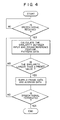
- Fig. 4 is a flowchart showing the operation of the word-interval detection circuit shown in Fig. 1;
- Fig. 5 shows examples of the frame data, similarity data and address data to be stored in the registers in the similarity data generating circuit shown in Fig. 2;
- Fig. 6 shows probable speech intervals each having the length which is substantially equal to the speech interval of the input speech and is constituted by a subperiod or a combination of subperiods determined by the frame data shown in Fig. 5;
- Fig. 7 shows an example of detail feature parameter data sequentially generated from an acoustic analyzer shown in Fig. 1; and
- Figs. 8A to 8D show detail feature pattern data obtained by selectively re-sampling the detail feature parameter data shown in Fig. 7.
- Fig. 1 is a block diagram showing a continuous speech recognition apparatus according to one embodiment of the present invention. This continuous speech recognition apparatus comprises a
microphone 2 to generate an electrical speech signal in accordance with input speeches; anacoustic analyzer 4 to extract rough and detail feature parameter data from the speech signal supplied from thismicrophone 2 for every frame; andreference memories acoustic analyzer 4 includes an A/D converter to convert the speech signal from themicrophone 2 into a digital signal at every 0.1 msec, for example, N band-pass filters which commonly receive the digital signal from this A/D converter and generate the output signals having the frequency bands to be obtained by dividing the frequency band of the speech signal into N channels (where, N is an integer of, e.g. 16 to 32), and N acoustic energy level detectors respectively connected to the band-pass filters. Thus, the feature parameter data including N parameters corresponding to the speech signal components having N frequency bands, respectively, is extracted as a part of the detail feature pattern data from thisacoustic analyzer 4 and is stored in the buffer memory at every 10 msec, for example. In addition, by combining the output signals of the N band-pass filters to M groups (where, M is an integer of, e.g. 2 to 4), the feature parameter data including M parameters corresponding to M speech signal components having the frequency bands,-respectively, to be obtained by dividing the frequency band of the speech signal into M channels is extracted as a part of the rough feature pattern data from theacoustic analyzer 4 and is stored in the buffer memory at every 10 msec. In this case, for example, the buffer memories to store part of the rough and detail feature pattern data are each constituted so as to have the memory capacity in which one-frame feature parameter data can be stored. - The
reference memory 6 stores a plurality of reference pattern data, each schematically representing the front portion of each of a plurality of words to be registered, and each having F1 frames of feature parameter data which are each formed of M parameters. On the other hand, thereference memory 8 stores a plurality of reference pattern data, each representing the above-mentioned plurality of words in detail, and each having F2 frames of reference parameter data which are each formed of N parameters. - In addition, this recognition apparatus includes a probable-word-
interval detection circuit 10 which fetches the rough feature parameter data from theacoustic analyzer 4 at every 10 msec, for example, and calculates the similarity between the rough feature pattern data constituted by the rough feature parameter data of F1 frames and all of the rough reference pattern data stored in thereference memory 6. - This probable-word-
interval detection circuit 10 comprises a speech interval detector 10-1 to detect the speech interval on the basis of the rough feature parameter data from theacoustic analyzer 4; a buffer memory 10-2 to sequentially store the rough feature parameter data from theacoustic analyzer 4 and consequently store the rough feature pattern data constituted by the rough feature parameter data of F1 frames; and a probable-word-interval detector 10-3 which calculates the similarity between the rough feature pattern data in this buffer memory 10-2 and rough reference pattern data in thereference memory 6 and generates, whenever the similarity of not lower than a preset value is obtained, the address data corresponding to the rough reference pattern data which gives this similarity and the frame data indicative of the position of the head frame of the rough feature pattern data which gives this similarity. - This word interval detector 10-3 is constituted by, for example, a similarity calculation circuit; a counter circuit which is reset in response to the output signal indicating the start of the speech interval from the above-mentioned speech interval detector 10-1, and thereafter which counts the number of times of the calculations executed in the above-mentioned similarity calculation circuit; an address converter to convert the address data supplied to the
reference memory 6 into the corresponding address data; and a control circuit which supplies the address data from the address converter to the outside whenever it is detected that the similarity of not lower than a preset value is obtained from the similarity calculation circuit, and at the same time which supplies the count data from the above-mentioned counter circuit as a frame data to the outside although these components are not shown in Fig. 1. This control circuit further supplies the output signal from the counter circuit to the outside even when the signal indicative of the end of the speech interval from the speech interval detector 10-1 is detected. - These frame data and address data from the
interval detection circuit 10 are supplied to a similaritydata generating circuit 12. This similaritydata generating circuit 12 calculates the similarity between the detail feature pattern data from theacoustic analyzer 4 in the probable word-intervals determined by the frame data and the detail reference pattern data read out from the memory location in thereference memory 8 designated by the address data from theinterval detection circuit 10. Then thecircuit 12 supplies the interval data relating to the probable word-intervals, word data in the respective probable word-intervals and similarity data calculated with respect to these word data to aword recognition circuit 14. Thisword recognition circuit 14 detects all combinations of the probable word-interval or intervals constituting one speech interval; detects the sum of the similarity data relating to the probable word-intervals of each combination; and extracts the word series represented by the combination of probable word-intervals of which the above-mentioned sum of the similarity data becomes maximum as effective word data. - As shown in Fig. 2, the similarity
data generating circuit 12 includes aframe register 20 and anaddress register 22 to sequentially store the frame data and address data from theinterval detection circuit 10, respectively; amemory 24 to sequentially store the detail feature parameter data from theacoustic analyzer 4; aninterval setting circuit 26 to set the word interval on the basis of the two frame data from theframe register 20; are-sampling pattern generator 28 to take the detail feature parameter data read out from thememory 24 in accordance with the frame pattern corresponding to the interval data from thisinterval setting circuit 26; and apattern register 30 to store the detail feature parameter data of F2 frames supplied from thememory 24 through thispattern generator 28. The similaritydata generating circuit 12 further includes asimilarity calculator 32 to calculate the similarity between the detail feature pattern data stored in the pattern register 30 and the corresponding reference pattern data read out from thememory 8; amaximum detector 34 to detect the maximum similarity from thissimilarity calculator 32; and aregister 36 to sequentially store the similarity data from thismaximum detector 34, front and rear frame data from theframe register 20, and address data from theaddress register 22. Acontrol circuit 38 also controls theframe register 20,address register 22 andmemory 24 in accordance with the front and rear frame data from theframe register 20. The similarity calculation in this embodiment can be carried out in accordance with multiple similarity calculation method disclosed in USP 3,688,267 or mixed similarity calculation method disclosed in USP 3,906,446. - The operations of the continuous speech recognition apparatus shown in Figs. 1 and 2 will be described hereinbelow.
- It is now considered the case where the speech having the acoustic power characteristic as shown in Fig. 3A is supplied to the
microphone 2. After this speech is converted into an electrical speech signal by thismicrophone 2, it is supplied to theacoustic analyzer 4. Thisacoustic analyzer 4 supplies the rough and detail feature parameter data in accordance with the input speech signal to the buffer 10-2 andmemory 24, respectively, for every frame. The speech interval detector 10-1 detects the speech interval to be determined by the time point when it is detected that the rough feature parameter data from thisacoustic analyzer 4 becomes a value not lower than a preset value and by the time point when it is detected that this rough feature parameter data becomes and is kept smaller than a.preset value for a predetermined period of time. - As shown in the flowchart of Fig. 4, the probable-word-interval detector 10-3 starts calculating the similarity between the rough feature pattern data in the buffer 10-2 and the rough reference pattern data in the
reference memory 6 in response to the output signal indicative of the start of the speech interval from the speech interval detector 10-1. This similarity calculation processing to each rough feature pattern data in the buffer 10-2 is executed at every 10 msec, for example. When this similarity becomes a value of not lower than a preset value, this word-interval detector 10-3 supplies the frame data with respect to the frame position of the head frame of the rough characteristic pattern data in the buffer 10-2 which gives this similarity, and the address data representative of the memory location in thereference memory 8 in which the detail reference pattern data corresponding to the rough reference pattern data in thereference memory 6 which gives this similarity is stored to the similaritydata generating circuit 10. The above-described operations are repeatedly executed until the speech signal is terminated. - Assume now that each similarity to words [X] and [Y] exceeds the preset value in the timings TS and T1 and in the timing T2, respectively, as shown in Figs. 3B and 3C. This means that the word [X] may be started at the respective timings TS and T1, and the word [Y] may be started at the timing T2. In this case, for example, the word-interval detector 10-3 generates frame data FR1 corresponding to the timing TS and address data X1 corresponding to word [Y], then generates frame data FR2 corresponding to the timing T2 and address data Y1 corresponding to word [Y]. Thereafter, it generates frame data FR3 corresponding to the timing T1 and address data X1 corresponding to word [X], and finally generates frame data FRE corresponding to the time point TE indicative of the end of the speech interval. In this case, as probable word-intervals where there is a possibility of existence of word [X], the intervals XW1, XW2, XW3, and XW4 to be defined by the timings TS and T2, timings TS and T1, timings TS and TE, and timings T1 and TE, respectively, are extracted as shown in Fig. 3D. On the other hand, as the probable word-intervals where there is a possibility of existence of word [Y], the intervals YW1 and YW2 to be defined by the timings T2 and T1, and timings T2 and TE, respectively, are extracted as shown in Fig. 3E.
- The
control circuit 38 in the similaritydata generating circuit 12 sets theframe register 20,address register 22 andmemory 24 into the readout mode in response to the output signal indicative of the termination of the speech signal from the interval detector 10-1. Thereafter thiscontrol circuit 38 permits theframe register 20 to supply the frame data FR1 and FR2 to theinterval setting circuit 26 and allows theaddress register 22 to supply the address data X1 to thereference memory 8. Thecircuit 38 further sequentially sends the readout address signals corresponding to the frame data FR1 and FR2 to thememory 24 and reads out the detail feature parameter data from the corresponding frame locations of thememory 24 for every frame. Theinterval setting circuit 26 supplies the output signal in response to the interval SW1 to there-sampling pattern generator 28 in accordance with the frame data FR1 and FR2. Due to this, there-sampling pattern generator 28 sequentially supplies the detail feature parameter data of F2 frames in predetermined frame positions among the detail feature parameter data of a plurality of frames which are read out from thememory 24 to thepattern register 30. In this way, the detail feature pattern data of N channels x F2 frames is stored in this pattern register 30 and the similarity with the reference pattern data read out from the memory location in thememory 8 which is designated by the address data X1 is calculated by thesimilarity calculator 32. This similarity data together with the frame data FR1 and FR2 and address data X1 is stored in theregister 36. When the similarity larger than a preset value with respect to different words in the same timing is detected by the word-interval detector 10-3, themaximum detector 34 extracts, as an effective similarity data, the maximum one of the similarity data obtained by thesimilarity calculator 32 with respect to these different words in the same word-interval. - The
control circuit 38 then sends a first control signal to theframe register 20 and permits this frame register 20 to generate the frame data FR3 from the second output port in place of the frame data FR2. Due to this theinterval setting circuit 26 supplies the output signal in response to the interval XW2 to there-sampling pattern generator 28. Thisre-sampling pattern generator 28 selectively supplies the detail feature parameter data of F2 frames among the detail feature parameter data which are sequentially read out from the frame positions corresponding to the interval XW2 in thememory 24 to thepattern register 30. Thereafter as already described previously, the similarity between the feature pattern data in this pattern register 30 and the reference pattern data read out from the memory location designated by the address data X1 in thereference memory 8 is calculated. This similarity data is stored in theregister 36 together with the frame data FR1 and FR3 and address data X1. - The
control circuit 38 then sends the first control signal to theframe register 20 and allows theframe register 20 to generate the frame data FRE from the second output port in place of the frame data FR3. Due to this, theinterval setting circuit 26 supplies the output signal corresponding to the interval XW3 to there-sampling pattern generator 28. Thereafter the same operations as described before are executed, so that the similarity data with respect to the interval XW3, frame data FR1 and FRE, and address data X1 are stored in theregister 36. - Thereafter the
control circuit 38 sends the first and second control signals to theframe register 20 and permits theframe register 20 to generate the frame data FR2 and FR3 from the first and second output ports in place of the frame data FR1 and FRE, respectively. Due to this, theinterval setting circuit 26 supplies the output signal in response to the interval YW1 to there-sampling pattern generator 28. In this case, there-sampling pattern generator 28 selects the detail feature parameter data of F2 frames among the detail feature parameter data to be sequentially read out from the frame positions corresponding to the interval YW1 in thememory 24 and supplies to thepattern register 30. After that, as described previously, the similarity between the feature pattern data in this pattern register 30 and the reference pattern data read out from the memory location designated by the address data Y1 in thereference memory 8 is calculated. This similarity data is stored in theregister 36 together with the frame data FR2 and FR3 are address data Y1. - Next, the
control circuit 38 sends the first control signal to theframe register 20 and allows this frame register 20 to generate the frame data FRE from the second output port in place of the frame data FR3. Thereafter the same operations as described before are executed, so that the similarity data with respect to the interval YW2, frame data FR2 and FRE, and address data Y1 are stored in theregister 36. - After that, the
control circuit 38 sends the first and second control signals to theframe register 20 and permits this frame register 20 to generate the frame data FR3 and FRE from the first and second output ports in place of the frame data FR2 and FRE. Thus, theinterval setting circuit 26 supplies the output signal in accordance with the interval XW4 to there-sampling pattern generator 28, thereby storing the detail feature parameter data of F2 frames in the frame positions corresponding to the interval XW4 in thememory 24 in thepattern register 30. Thereafter, in the same manner as described before, the similarity between the feature pattern data in this pattern register 30 and the reference pattern data read out from the memory location designated by the address data X1 in thereference memory 8 is calculated. This similarity data is stored in theregister 36 together with the frame data FR3 and FRE and address data X1. - As shown in Fig. 5, the two frame data indicative of the frame interval, similarity data, and address data are stored in the memory locations ML1 to ML6 in the
register 36, respectively, in such a manner as described above. As shown in Fig. 6, the individual data in these memory locations ML1 to ML6 represents the six word-intervals XW1 to XW4, YW1 and YW2 in the speech interval, and the similarity and address data with respect to those word-intervals. - The
word recognition circuit 14 creates all combinations in the frame intervals constituting the speech interval on the basis of the frame data in theregister 36. For instance, in this example described hereinabove, the frame intervals XW1, YW1 and XW4; frame intervals XW1 and YW2; frame intervals XW2 and XW4; and frame interval XW3 cooperatively or solely constitute the probable speech intervals S11 to S14, respectively. Theword recognition circuit 14 calculates the sum of the similarity data relating to the respective frame interval or intervals among the speech intervals SI1 to S14 and recognizes, as a series of effective words, a series of words determined by one of the speech intervals SI1 to SI4 having the maximum sum of similarity data. - Fig. 7 shows an example of detail feature parameter data sequentially generated from the
acoustic analyzer 4 and stored in the detailfeature pattern memory 24. The detail feature parameter data correspond to a speech signal representing "0, 2, 8, 7" (pronounced as "[zero], [ni], [hatfi], [nana]" in Japanese way)". In Fig. 7, the size of each black circle indicates the intensity of acoustic energy. In this example, each detail feature parameter data includes 16 parameters, and each of rough feature parameter data may be obtained by dividing 16 parameters into four groups. In this example, head frame positions of the feature pattern data representing "0", "2", "8" and "7" may be detected by sequentially calculating the similarity between the rough feature pattern data and the reference pattern data. Detail feature parameter data are selectively extracted from the sequence of feature parameter data in each word interval defined by the head frame positions. Figs. 8A to 8D show detail feature pattern data obtained by re-sampling the feature parameter data in respective word intervals corresponding to "0", "2", "8" and "7". The similarity between each of the detail feature pattern data and each of the detail reference pattern data is sequentially calculated so that word data representing "0", "2", "8" and "7" can be detected, and stored together with the word interval data and the similarity data. Using the word data, word interval data and similarity data, input may be recognized. - Although the present invention has been described in the above with respect to one embodiment, the invention is not limited to only this embodiment. For example, although the rough feature parameter data from the
acoustic analyzer 4 are sequentially stored in the buffer 10-2 for every one frame in the above-described embodiment, it is for example possible to store these rough feature parameter data in the buffer 10-2 for every other frame using a logical control circuit which is ordinarily well known. - Furthermore, in the above embodiment, until the frame data from the second output port of the
frame register 20 becomes equal to "FRE", the frame data are sequentially generated from this second output port in accordance with the write- in order, and after this frame data from the second output port becomes equal to "FRE", the frame data at the first and second output port are changed so that, the interval data with respect to all of the word intervals defined by the frame data FR1 to FR3 and FRE in the speech intervals are generated from thisframe register 20. However, if all of the interval data are generated, its sequence of generation should not be limited. - Furthermore,. although the rough reference pattern data indicative of the front portion of the detailed reference pattern of each word are stored in the
reference memory 6, it is possible to store the rough reference pattern data representative of the rear portion or central portion of the detailed reference pattern of each word in place of that data in thisreference memory 6. Of course in this case, the frame data to be generated from the . probable-word-interval detector 10-3 represents the rear end or central frame position of the corresponding feature pattern data; therefore, in order to determine the word-interval data, the data processing should be changed accordingly. - In addition, in the above-described embodiment, words are used as a speech segment unit of the input speech to be recognized; however, it may be possible to recognize the input speech for every syllable, clause, or other speech segment unit.
- It is also possible to remove the
re-sampling pattern generator 28 and to use a readout circuit for sequentially applying F2 readout address signals to thememory 24 in response to the readout address signals from thecontrol circuit 38 and the interval data from theinterval setting circuit 26. - Furthermore, even if the detail feature parameter data or the output signal of the
microphone 2 is supplied to the speech interval detector 10-1 in place of the rough feature parameter data, it is possible to detect the speech interval.
Claims (5)
Applications Claiming Priority (2)
| Application Number | Priority Date | Filing Date | Title |
|---|---|---|---|
| JP57227709A JPS59121100A (en) | 1982-12-28 | 1982-12-28 | Continuous voice recognition equipment |
| JP227709/82 | 1982-12-28 |
Publications (2)
| Publication Number | Publication Date |
|---|---|
| EP0112717A1 EP0112717A1 (en) | 1984-07-04 |
| EP0112717B1 true EP0112717B1 (en) | 1987-06-10 |
Family
ID=16865119
Family Applications (1)
| Application Number | Title | Priority Date | Filing Date |
|---|---|---|---|
| EP83307796A Expired EP0112717B1 (en) | 1982-12-28 | 1983-12-21 | Continuous speech recognition apparatus |
Country Status (4)
| Country | Link |
|---|---|
| US (1) | US4677673A (en) |
| EP (1) | EP0112717B1 (en) |
| JP (1) | JPS59121100A (en) |
| DE (1) | DE3372029D1 (en) |
Families Citing this family (21)
| Publication number | Priority date | Publication date | Assignee | Title |
|---|---|---|---|---|
| US5241649A (en) * | 1985-02-18 | 1993-08-31 | Matsushita Electric Industrial Co., Ltd. | Voice recognition method |
| JPS61252594A (en) * | 1985-05-01 | 1986-11-10 | 株式会社リコー | Audio pattern matching method |
| US5774851A (en) * | 1985-08-15 | 1998-06-30 | Canon Kabushiki Kaisha | Speech recognition apparatus utilizing utterance length information |
| US4802224A (en) * | 1985-09-26 | 1989-01-31 | Nippon Telegraph And Telephone Corporation | Reference speech pattern generating method |
| JPH06105394B2 (en) * | 1986-03-19 | 1994-12-21 | 株式会社東芝 | Voice recognition system |
| US4882755A (en) * | 1986-08-21 | 1989-11-21 | Oki Electric Industry Co., Ltd. | Speech recognition system which avoids ambiguity when matching frequency spectra by employing an additional verbal feature |
| JPH0760318B2 (en) * | 1986-09-29 | 1995-06-28 | 株式会社東芝 | Continuous speech recognition method |
| JPS63158596A (en) * | 1986-12-23 | 1988-07-01 | 株式会社東芝 | Phoneme analogy calculator |
| US5027407A (en) * | 1987-02-23 | 1991-06-25 | Kabushiki Kaisha Toshiba | Pattern recognition apparatus using a plurality of candidates |
| DE3888777T2 (en) * | 1987-10-06 | 1994-07-14 | Toshiba Kawasaki Kk | Method and device for speech recognition. |
| JPH0225898A (en) * | 1988-07-15 | 1990-01-29 | Toshiba Corp | Voice recognizing device |
| JPH02150899A (en) * | 1988-12-02 | 1990-06-11 | Toshiba Corp | Voice recognition system |
| CA2040025A1 (en) * | 1990-04-09 | 1991-10-10 | Hideki Satoh | Speech detection apparatus with influence of input level and noise reduced |
| DE69128990T2 (en) * | 1990-09-07 | 1998-08-27 | Toshiba Kawasaki Kk | Speech recognition device |
| US5386492A (en) * | 1992-06-29 | 1995-01-31 | Kurzweil Applied Intelligence, Inc. | Speech recognition system utilizing vocabulary model preselection |
| US5682464A (en) * | 1992-06-29 | 1997-10-28 | Kurzweil Applied Intelligence, Inc. | Word model candidate preselection for speech recognition using precomputed matrix of thresholded distance values |
| US5428707A (en) * | 1992-11-13 | 1995-06-27 | Dragon Systems, Inc. | Apparatus and methods for training speech recognition systems and their users and otherwise improving speech recognition performance |
| US6092043A (en) * | 1992-11-13 | 2000-07-18 | Dragon Systems, Inc. | Apparatuses and method for training and operating speech recognition systems |
| US5920836A (en) * | 1992-11-13 | 1999-07-06 | Dragon Systems, Inc. | Word recognition system using language context at current cursor position to affect recognition probabilities |
| DE60032776T2 (en) * | 2000-11-16 | 2007-11-08 | Sony Deutschland Gmbh | Method for speech recognition |
| US9646603B2 (en) * | 2009-02-27 | 2017-05-09 | Longsand Limited | Various apparatus and methods for a speech recognition system |
Family Cites Families (1)
| Publication number | Priority date | Publication date | Assignee | Title |
|---|---|---|---|---|
| US4107460A (en) * | 1976-12-06 | 1978-08-15 | Threshold Technology, Inc. | Apparatus for recognizing words from among continuous speech |
-
1982
- 1982-12-28 JP JP57227709A patent/JPS59121100A/en active Pending
-
1983
- 1983-12-21 DE DE8383307796T patent/DE3372029D1/en not_active Expired
- 1983-12-21 EP EP83307796A patent/EP0112717B1/en not_active Expired
- 1983-12-21 US US06/563,755 patent/US4677673A/en not_active Expired - Fee Related
Non-Patent Citations (5)
| Title |
|---|
| ASSP 23/1, pages 50-53 * |
| ASSP 24/2 pages 171-182 * |
| ASSP 28/4 pages 377-388 * |
| PROCEEDINGS OF THE FOURTH INTERNATIONAL JOINT CONFERENCE ON PATTERN RECOGNITION, November 7-10, 1978, Kyoto, Japan, IEEE, New York (US) S. CHIBA et al: "A speaker-independent word recognition system", pages 995-999 * |
| SYSTEMS, COMPUTERS, CONTROLS, vol. 9, no. 3, May-June 1978, Silver Spring, Maryland (US) S. NAKAGAWA et al: "A real-time spoken word recognition system with various learning capabilities of speaker differences", pages 63-71 * |
Also Published As
| Publication number | Publication date |
|---|---|
| JPS59121100A (en) | 1984-07-12 |
| EP0112717A1 (en) | 1984-07-04 |
| US4677673A (en) | 1987-06-30 |
| DE3372029D1 (en) | 1987-07-16 |
Similar Documents
| Publication | Publication Date | Title |
|---|---|---|
| US4677673A (en) | Continuous speech recognition apparatus | |
| US4651289A (en) | Pattern recognition apparatus and method for making same | |
| US4513435A (en) | System operable as an automaton for recognizing continuously spoken words with reference to demi-word pair reference patterns | |
| US5018201A (en) | Speech recognition dividing words into two portions for preliminary selection | |
| US4481593A (en) | Continuous speech recognition | |
| US4736429A (en) | Apparatus for speech recognition | |
| US4955056A (en) | Pattern recognition system | |
| US4962535A (en) | Voice recognition system | |
| EP0082000B1 (en) | Dp matching system for recognizing a string of words | |
| JPH0352640B2 (en) | ||
| US4769844A (en) | Voice recognition system having a check scheme for registration of reference data | |
| US5101434A (en) | Voice recognition using segmented time encoded speech | |
| EP0114500B1 (en) | Continuous speech recognition apparatus | |
| US4987596A (en) | Knowledge-guided automatic speech recognition apparatus and method | |
| US4852171A (en) | Apparatus and method for speech recognition | |
| US4924518A (en) | Phoneme similarity calculating apparatus | |
| JPS6138479B2 (en) | ||
| EP0215573B1 (en) | Apparatus and methods for speech recognition | |
| US4790017A (en) | Speech processing feature generation arrangement | |
| EP0177854B1 (en) | Keyword recognition system using template-concatenation model | |
| Can et al. | A syllable-based Turkish speech recognition system by using time delay neural networks (TDNNs) | |
| JPS57212586A (en) | Character recognizing system | |
| JP2757356B2 (en) | Word speech recognition method and apparatus | |
| CA2013263C (en) | Rejection method for speech recognition | |
| CA1258917A (en) | Apparatus and method for identifying spoken words |
Legal Events
| Date | Code | Title | Description |
|---|---|---|---|
| PUAI | Public reference made under article 153(3) epc to a published international application that has entered the european phase |
Free format text: ORIGINAL CODE: 0009012 |
|
| 17P | Request for examination filed |
Effective date: 19840111 |
|
| AK | Designated contracting states |
Designated state(s): DE FR GB IT NL |
|
| RAP1 | Party data changed (applicant data changed or rights of an application transferred) |
Owner name: KABUSHIKI KAISHA TOSHIBA |
|
| GRAA | (expected) grant |
Free format text: ORIGINAL CODE: 0009210 |
|
| AK | Designated contracting states |
Kind code of ref document: B1 Designated state(s): DE FR GB |
|
| REF | Corresponds to: |
Ref document number: 3372029 Country of ref document: DE Date of ref document: 19870716 |
|
| ET | Fr: translation filed | ||
| PLBE | No opposition filed within time limit |
Free format text: ORIGINAL CODE: 0009261 |
|
| STAA | Information on the status of an ep patent application or granted ep patent |
Free format text: STATUS: NO OPPOSITION FILED WITHIN TIME LIMIT |
|
| 26N | No opposition filed | ||
| PGFP | Annual fee paid to national office [announced via postgrant information from national office to epo] |
Ref country code: FR Payment date: 19961211 Year of fee payment: 14 |
|
| PGFP | Annual fee paid to national office [announced via postgrant information from national office to epo] |
Ref country code: GB Payment date: 19961212 Year of fee payment: 14 |
|
| PGFP | Annual fee paid to national office [announced via postgrant information from national office to epo] |
Ref country code: DE Payment date: 19961231 Year of fee payment: 14 |
|
| PG25 | Lapsed in a contracting state [announced via postgrant information from national office to epo] |
Ref country code: GB Free format text: LAPSE BECAUSE OF NON-PAYMENT OF DUE FEES Effective date: 19971221 |
|
| PG25 | Lapsed in a contracting state [announced via postgrant information from national office to epo] |
Ref country code: FR Free format text: THE PATENT HAS BEEN ANNULLED BY A DECISION OF A NATIONAL AUTHORITY Effective date: 19971231 |
|
| GBPC | Gb: european patent ceased through non-payment of renewal fee |
Effective date: 19971221 |
|
| PG25 | Lapsed in a contracting state [announced via postgrant information from national office to epo] |
Ref country code: DE Free format text: LAPSE BECAUSE OF NON-PAYMENT OF DUE FEES Effective date: 19980901 |
|
| REG | Reference to a national code |
Ref country code: FR Ref legal event code: ST |