EP0112248B1 - Method and apparatus for electrically determining pipe inside diameter - Google Patents
Method and apparatus for electrically determining pipe inside diameter Download PDFInfo
- Publication number
- EP0112248B1 EP0112248B1 EP83402412A EP83402412A EP0112248B1 EP 0112248 B1 EP0112248 B1 EP 0112248B1 EP 83402412 A EP83402412 A EP 83402412A EP 83402412 A EP83402412 A EP 83402412A EP 0112248 B1 EP0112248 B1 EP 0112248B1
- Authority
- EP
- European Patent Office
- Prior art keywords
- pipe
- signal
- inside diameter
- generating
- transmitter
- Prior art date
- Legal status (The legal status is an assumption and is not a legal conclusion. Google has not performed a legal analysis and makes no representation as to the accuracy of the status listed.)
- Expired
Links
Images


Classifications
-
- G—PHYSICS
- G01—MEASURING; TESTING
- G01B—MEASURING LENGTH, THICKNESS OR SIMILAR LINEAR DIMENSIONS; MEASURING ANGLES; MEASURING AREAS; MEASURING IRREGULARITIES OF SURFACES OR CONTOURS
- G01B7/00—Measuring arrangements characterised by the use of electric or magnetic techniques
- G01B7/02—Measuring arrangements characterised by the use of electric or magnetic techniques for measuring length, width or thickness
- G01B7/06—Measuring arrangements characterised by the use of electric or magnetic techniques for measuring length, width or thickness for measuring thickness
- G01B7/10—Measuring arrangements characterised by the use of electric or magnetic techniques for measuring length, width or thickness for measuring thickness using magnetic means, e.g. by measuring change of reluctance
-
- E—FIXED CONSTRUCTIONS
- E21—EARTH OR ROCK DRILLING; MINING
- E21B—EARTH OR ROCK DRILLING; OBTAINING OIL, GAS, WATER, SOLUBLE OR MELTABLE MATERIALS OR A SLURRY OF MINERALS FROM WELLS
- E21B47/00—Survey of boreholes or wells
- E21B47/08—Measuring diameters or related dimensions at the borehole
- E21B47/085—Measuring diameters or related dimensions at the borehole using radiant means, e.g. acoustic, radioactive or electromagnetic
Definitions
- This invention relates generally to a method and apparatus for electromagnetically measuring the inside diameter of a cylindrical structure and particularly relates to an electronic inside pipe caliper. More particularly, the invention relates to a method and apparatus for logging the inside diameter of oil and gas well tubular members, e.g., casing.
- Such metallic pipes are buried in the ground and, therefore, are not accessible for measurement. Both the inside and the outside of each metallic pipes is subject to corrosion damage. The corrosion may be caused by injected fluids or by corrosive fluids within the ground. Besides, the pipe may be subjected to internal wear from the rods of pumps or from wear due to wire lines which may be sent into the well. Also, wear may be caused by drilling or fishing operations utilizing a drill pipe.
- Measuring the damage of a pipe due to corrosion or wear is important in order to apply protective measures or to repair or replace the pipe when appopriate.
- Some of these mechanical feeler calipers utilize two sets of feelers, one for measuring the maximum penetration of the feeler, while the other continuously measures the average penetration of the feelers.
- a pipe caliper of the type having mechanical feelers has a number of disadvantages.
- such an instrument cannot detect longitudinal splits or cracks of the pipe.
- the pipe may be covered with paraffin, scale or other non-metallic material which may cover up faults in the pipe.
- the feeler of course, cannot distinguish between a metallic pipe and non-metallic material which may cover the pipe. Therefore, certain pits covered by hardened hydrocarbons and the like cannot be detected.
- each of the many feelers may scratch the pipe or scratch off the protective coating of the pipe. Even if the pipe has not been covered with a protective coating, the scratches caused by the feelers may initiate further corrosion. Consequently, the mechanical feeler-type instrument may cause change to the pipe inside diameter it is intended to measure.
- U.S. Patent US ⁇ A ⁇ 3,417,325 issued to McCullough and Stroud discloses a purely electrical caliper for determining the inside diameter of a metallic pipe in which a transmitter coil and receiver coil are supported on a cylindrical housing of a sonde adapted for movement through oil well casings and the like.
- the transmitter is excited with a.c. current of the order of 10 to 50 KHz.
- the voltage induced in the receiver coil is taken as a measure of the average inside diameter of the pipe being measured.
- Another object of the invention is to provide an inside pipe caliper which generates a signal representative of the inside diameter of the pipe which is substantially insensitive to variations of conductivity and permeability of the pipe.
- Another object of this invention is to provide well logging apparatus for logging borehole casing or tubing which yields an accurate log of the inside diameter of the casing versus depth, regardless of variations of casing conductivity or permeability.
- the objects, features and advantages of the invention are the result of providing two coaxial coils within the pipe including a transmitter coil in which is generated an a.c. exciting current, and a receiver coil disposed a longitudinal distance from the transmitter coil for producing an induced voltage in response to the transmitter current.
- a circuit is provided to generate an impedance signal proportional to the ratio of the receiver voltage to the transmitter current.
- the impedance signal is resolved into its vector components including a quadrature impedance signal and an inphase impedance signal.
- means responsive to the quadrature and the inphase impedance signals are provided to generate a corrected measurement output.
- This corrected measurement output is used to generate a signal representative of the inside diameter of the pipe.
- means are provided for linearly combining the quadrature and the inphase impedance signals to generate a corrected measurement output having a lessened sensitivity to the permeability and conductivity of metallic objects.
- means are provided for simultaneously solving two non-linear equations which express the quadrature and inphase impedance siganls as functions of a,, the inside radius of the pipe, and ⁇ , a parameter proportional to the ratio of the permeability of the pipe to the conductivity of the pipe.
- an iterative computing method for simultaneously solving the two equations by first assuming that T is equal to zero, then determining an estimate of a 1 from the first equation, determining T from the second equation, using the new T value in the first equation to determine a new value of a 1 and repeating the method until convergence is achieved.
- a method of measuring the inside diameter of a metallic pipe is outlined in claim 10.
- Figure 1 shows schematically an electrical caliper tool 10 constructed in accordance with the invention.
- the tool 10 determines the inside diameter of tubular members, shown illustratively as casing 20 of borehole 16.
- the tool includes a downhole sonde 12, downhole electronic cartridge 13, and surface equipment 14.
- the sonde 12 is adapted to be suspended in and movable through the tubular member or casing 20 by an armored cable, or wireline 18.
- the well bore 16 has a casing 20 having an inside diameter Which the tool 10 is designed to measure as a function of well depth as the tool is raised or lowered within the casing 20.
- the wireline or cable 18 may be a single conductor (referred to as mono-cable) or multi-conductor (which may be a heptacable having seven conductors).
- the surface equipment 14 communicates with the sonde 12 via the cable 18 for the purposes of controlling the position of the sonde 12 within the casing 20 and for receiving, processing, displaying, and recording signals transmitted from the sonde 12.
- a cable-following mechanical transducer 22 and linkage 23 provides position signals indicative of the depth of the sonde 12 in the well bore 16.
- the transducer 22 takes the form of a calibrated pressure wheel urged against the wireline 18 and generates electrical pulses as the wheel rotates due to travel of the sonde 12 within the casing.
- the down hole tool comprises a sonde 12, an electronic cartridge section 13, a pair of centralizers 27a, 27b, a tip or nose member 28 and a cable head adapter 30.
- the down hole tool is connected to the cable 18 via the cable head adapter 30.
- the sonde 12 contains caliper coils 50, 60 for making electromagnetic measurements as a function of depth of the sonde in the casing.
- a signal is generated which is proportional to casing inside diameter.
- Other signals are generated which are representative of the ratio of casing permeability to casing conductivity.
- Figure 2 shows a theoretical model of two coaxial coils 50, 60 separated from one another by a longitudinal distance L, both coils disposed coaxially within pipe or casing 20.
- the pipe inside radius is represented by a,, its outside radius by a z .
- the radius of receiver coil 60 is represented by b 2 ; the raduis of transmitter coil 50 is represented by b 1 .
- the electrical properties of medium 1 inside the pipe are e 1 , ⁇ 1 ⁇ 1 , the permittivity, the permeability and the conductivity of the medium.
- the properties of the pipe are represented by ⁇ 2 , ⁇ 2 , ⁇ 2 .
- Equation (4) can be expanded using equation (5) for r and equation (6) for T,
- the measured impedance between the coils, Z meas has real and imaginary (quadrature) parts
- Equation 12 indicates that where the coils 50 and 60 are of the same diameter b, the medium 1 permeability is that of free space ⁇ o and and when T from equation 9 is not small enough to ignore, it can be shown that where, where a 1 represents the inside radius of the pipe,
- an accurate determination of a 1 the inside radius of the pipe 20, can be made by measuring the impedance between the coils, resolving the impedance into its quadrature (imaginary) and inphase (real) components, taking the difference between those components and determining a 1 which satisfies equation 14.
- equation 14 may be precomputed for various AZ values as a function of a 1 .
- a polynomial may be fitted to the functional relationship between a 1 and ⁇ Z, or
- the polynomial may be stored in the memory of a digital computer disposed in surface instrumentation 14, so that as AZ is measured as a function of depth in the well 16, a 1 may be easily determined.
- equation (13) may be predetermined over a range of values of AZ and a 1 to produce a table of values which may be stored in a digital memory in surface instrumentation 14.
- the digital memory may then be addressed with a measured ⁇ Z value to generate a signal a 1 representative of the inside diameter of the pipe.
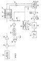
- FIG. 3 illustrates the electronic circuitry necessary to implement the invention.
- Caliper coils 50,60 are shown schematically within casing 20.
- Transmitter coil 50 is excited by means of a 65.5 kHz crystal oscillator via summing amplifier 101 and driver amplifier 102.
- a current sensing resistor provides an output to sensing amplifier 104 proportional to the current through transmitter coil 50.
- the output of sensing amplifier 104 is applied to rectifier 105 where a rectified error signal is applied to a differential error amplifier 106 for comparison with a reference signal.
- the error signal from error amplifier 106 is fed back to summing amplifier 101, completing the feedback constant current circuit.
- the signal from current sensing resistor 103 is applied to phase-locked loop oscillator 110 which generates reference signals in quadrature (e.g. 90° out of phase) with the transmitter current, on lead 111 and inphase (e.g., 180° out of phase) with transmitter current on lead 112.
- the current reference signal is also applied to switch network 120.
- a ground signal on lead 116 is additionally applied to switch network 120.
- switch network 120 it is possible to apply not only the received voltage on leads 115 to phase sensitive detector 130, but also a current signal on 113 and a ground signal 116, thereby providing ready means to calibrate the phase sensitive detector (PSD) 130 system for misalignment and drifts with temperature and time.
- PSD phase sensitive detector
- the signal from switch network 120 is applied to PSD 130 via differential amplifier 121 and band pass filter 122 having a band pass frequency substantially the same as that of oscillator 100.
- the output of the PSD 130 is applied to a low-pass filter 131, the output of which during logging operations is alternatively the inphase and quadrature components of the voltage signal indicated in coil 60 measured with respect to the phase of the current driving transmitter coil 50.
- Switch S is alternately connected to leads 111, 112 many times each second thereby producing many output readings each second, effectively insuring that for each depth location that coils 50, 60 are measuring, several outputs of the inphase and quadrature components are available for further processing as described previously to generate an inside diameter measurement and a T measurement indicative of the ratio of pipe permeability to conductivity.
- the circuitry of Figure 3 is preferably disposed in electronic cartridge 13, but may alternatively partially or totally reside in surface instrumentation, except input and output leads to coils 50 and 60.
- signals from the phase sensitive detector 130 are applied to surface instrumentation circuits 14 by means of telemetry circuits downhole and demodulation circuits uphole similar to that shown in U.S. Patent US-A-4,292,588 issued to Smith and incorporated herein.
- Coils 50 and 60 may be shielded in a conventional manner so as to prevent electric field coupling where logging is occurring in a salt-water filled environment.
- Well logs of casing inside diameter are effected through the apparatus shown in Figures 1 and 3 and the processing steps outlined above are preferably carried out in surface instrumentation 14.
- Logs are generated by correlating the depth signals of the coils 50, 60 through the use of measurement wheel 22 schematically shown connected to surface instrumentation 15, well known in the well logging art.
- a recorder 100 is provided for producing logs of casing inside diameter versus depth of the coils 50, 60.
- the parameter T proportional to the permeability-conductivity ratio may also be recorded as a function of logging depth.
- Figures 4A and 4B illustrate the efficacy of the invention in producing measurements of the inside diameter of tubular goods having wide variations in conductivity.
- Figure 4A shows that significant errors result in the apparent inside diameter of pipe for tubular brass, stainless steel, aluminum and other ferrous pipes having different permeability-conductivity ratios.
- the results of Figure 4A were generated in the prior known way of estimating inside diameter purely on the basis of the magnitude of received voltage of receiver coil 60.
- Figure 4B shows that by providing the corrections indicated by equations 13 and 14 above, errors to the estimate of pipe inside diameter are significantly reduced.
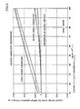
- Figure 5 illustrates the error expected in the measurement using the first order correction of equations 13 and 14 and the scond order correction of equations 15 through 22.
- the error curves are presented as a function of Li/6 of the tube under investigation and shows curves of casing inside diameters of 4, 5, 6, and 7 inches (i.e. 101.6,127,152.4 and 177.8 mm). It is seen that substantial reduction in casing inside diameter errors are achieved for large pla ratios.
Landscapes
- Physics & Mathematics (AREA)
- Mining & Mineral Resources (AREA)
- Geology (AREA)
- Life Sciences & Earth Sciences (AREA)
- Engineering & Computer Science (AREA)
- Geochemistry & Mineralogy (AREA)
- Fluid Mechanics (AREA)
- Environmental & Geological Engineering (AREA)
- Electromagnetism (AREA)
- Geophysics (AREA)
- General Physics & Mathematics (AREA)
- General Life Sciences & Earth Sciences (AREA)
- Investigating Or Analyzing Materials By The Use Of Magnetic Means (AREA)
- Length Measuring Devices With Unspecified Measuring Means (AREA)
- Length Measuring Devices By Optical Means (AREA)
- Length-Measuring Devices Using Wave Or Particle Radiation (AREA)
- Investigating Or Analyzing Materials By The Use Of Electric Means (AREA)
- Measurement Of Length, Angles, Or The Like Using Electric Or Magnetic Means (AREA)
Applications Claiming Priority (4)
| Application Number | Priority Date | Filing Date | Title |
|---|---|---|---|
| US449016 | 1982-12-13 | ||
| US449015 | 1982-12-13 | ||
| US06/449,015 US4546315A (en) | 1982-12-13 | 1982-12-13 | Apparatus for measuring the inside diameter of a metallic pipe in a well |
| US06/449,016 US4546314A (en) | 1982-12-13 | 1982-12-13 | Method and apparatus for measuring the inside diameter of a metallic pipe in a well |
Publications (2)
| Publication Number | Publication Date |
|---|---|
| EP0112248A1 EP0112248A1 (en) | 1984-06-27 |
| EP0112248B1 true EP0112248B1 (en) | 1987-02-04 |
Family
ID=27035566
Family Applications (1)
| Application Number | Title | Priority Date | Filing Date |
|---|---|---|---|
| EP83402412A Expired EP0112248B1 (en) | 1982-12-13 | 1983-12-13 | Method and apparatus for electrically determining pipe inside diameter |
Country Status (10)
| Country | Link |
|---|---|
| EP (1) | EP0112248B1 (enExample) |
| AU (1) | AU567135B2 (enExample) |
| BR (1) | BR8306849A (enExample) |
| DE (1) | DE3369728D1 (enExample) |
| DK (1) | DK167713B1 (enExample) |
| EG (1) | EG15994A (enExample) |
| IN (1) | IN162847B (enExample) |
| MX (1) | MX154073A (enExample) |
| NO (1) | NO166897C (enExample) |
| OA (1) | OA07610A (enExample) |
Cited By (2)
| Publication number | Priority date | Publication date | Assignee | Title |
|---|---|---|---|---|
| CN102168550A (zh) * | 2011-03-30 | 2011-08-31 | 江苏方建工程质量鉴定检测有限公司 | 一种井中地电位测量电极 |
| WO2017151123A1 (en) * | 2016-03-02 | 2017-09-08 | Halliburton Energy Services, Inc. | A space mapping optimization to characterize multiple concentric pipes |
Families Citing this family (7)
| Publication number | Priority date | Publication date | Assignee | Title |
|---|---|---|---|---|
| GB2158245B (en) * | 1984-05-04 | 1988-09-01 | Nl Industries Inc | Detection of location of pipe stuck in a borehole |
| DE3506622A1 (de) * | 1985-02-26 | 1986-08-28 | Hermann Dipl.-Ing. 4450 Lingen Rosen | Molch fuer eine fortlaufende messung und registrierung der innengeometrie einer rohrleitung |
| FR2700806B1 (fr) * | 1993-01-27 | 1995-03-17 | Elf Aquitaine | Procédé de détermination des variations de la morphologie d'un puits de forage. |
| FR2752935B1 (fr) | 1996-08-30 | 1998-09-18 | Commissariat Energie Atomique | Procede de mesure d'un volume conducteur et dispositif de mise en oeuvre de ce procede |
| CN110470205B (zh) * | 2019-08-13 | 2021-07-09 | 森泰英格(成都)数控刀具股份有限公司 | 无源线圈感应检测自动识别刀柄的方法 |
| CN113550741B (zh) * | 2020-04-26 | 2025-07-15 | 中国石油化工股份有限公司 | 一种套管最小内径检测方法 |
| CN113916121B (zh) * | 2021-09-17 | 2024-06-21 | 山东兰海新材料科技有限公司 | 金属微细线直径检测方法与装置 |
Family Cites Families (6)
| Publication number | Priority date | Publication date | Assignee | Title |
|---|---|---|---|---|
| US3405349A (en) * | 1965-04-07 | 1968-10-08 | Schlumberger Technology Corp | Well logging with borehole effect compensation and including memory storage of borehole measurements |
| US3417325A (en) * | 1968-02-15 | 1968-12-17 | Ira J. Mccullough | Inside pipe diameter caliper using coaxial excitation and pickup coils |
| US3532969A (en) * | 1968-02-20 | 1970-10-06 | Nat Lead Co | Method for magnetically measuring wall thickness of metal pipes and plate structures |
| AU436753B2 (en) * | 1968-09-19 | 1973-06-08 | JOHNSON McCULLOUGH and STANLEY GROVER STROUD ira | Inside pipe diameter caliper using coaxial excitation and pick up coils |
| US3727126A (en) * | 1970-09-11 | 1973-04-10 | Sev Kavkazsky Neftyanol Ni | Profilograph for examining pipes in oil wells |
| US4292588A (en) * | 1978-12-18 | 1981-09-29 | Schlumberger Technology Corporation | Electromagnetic inspection tool for ferromagnetic casings |
-
1983
- 1983-11-24 NO NO834317A patent/NO166897C/no unknown
- 1983-12-12 AU AU22328/83A patent/AU567135B2/en not_active Ceased
- 1983-12-13 EG EG771/83A patent/EG15994A/xx active
- 1983-12-13 MX MX199724A patent/MX154073A/es unknown
- 1983-12-13 BR BR8306849A patent/BR8306849A/pt not_active IP Right Cessation
- 1983-12-13 EP EP83402412A patent/EP0112248B1/en not_active Expired
- 1983-12-13 OA OA58182A patent/OA07610A/xx unknown
- 1983-12-13 IN IN1520/CAL/83A patent/IN162847B/en unknown
- 1983-12-13 DK DK573583A patent/DK167713B1/da not_active IP Right Cessation
- 1983-12-13 DE DE8383402412T patent/DE3369728D1/de not_active Expired
Cited By (5)
| Publication number | Priority date | Publication date | Assignee | Title |
|---|---|---|---|---|
| CN102168550A (zh) * | 2011-03-30 | 2011-08-31 | 江苏方建工程质量鉴定检测有限公司 | 一种井中地电位测量电极 |
| CN102168550B (zh) * | 2011-03-30 | 2013-04-24 | 江苏方建工程质量鉴定检测有限公司 | 一种井中地电位测量电极 |
| WO2017151123A1 (en) * | 2016-03-02 | 2017-09-08 | Halliburton Energy Services, Inc. | A space mapping optimization to characterize multiple concentric pipes |
| GB2559074A (en) * | 2016-03-02 | 2018-07-25 | Halliburton Energy Services Inc | A space mapping optimization to characterize multiple concentric pipes |
| US11655702B2 (en) | 2016-03-02 | 2023-05-23 | Halliburton Energy Services, Inc. | Space mapping optimization to characterize multiple concentric pipes |
Also Published As
| Publication number | Publication date |
|---|---|
| AU2232883A (en) | 1984-06-21 |
| DK167713B1 (da) | 1993-12-06 |
| EG15994A (en) | 1987-10-30 |
| DK573583D0 (da) | 1983-12-13 |
| NO166897C (no) | 1991-09-11 |
| DK573583A (da) | 1984-06-14 |
| MX154073A (es) | 1987-04-27 |
| DE3369728D1 (en) | 1987-03-12 |
| EP0112248A1 (en) | 1984-06-27 |
| BR8306849A (pt) | 1984-07-24 |
| AU567135B2 (en) | 1987-11-12 |
| IN162847B (enExample) | 1988-07-16 |
| OA07610A (en) | 1985-03-31 |
| NO834317L (no) | 1984-06-14 |
| NO166897B (no) | 1991-06-03 |
Similar Documents
| Publication | Publication Date | Title |
|---|---|---|
| US4546314A (en) | Method and apparatus for measuring the inside diameter of a metallic pipe in a well | |
| US7960969B2 (en) | Electromagnetic imaging method and device | |
| EP0384537B1 (en) | Method to improve directional survey accuracy | |
| EP1717412B1 (en) | A method for electromagnetically measuring physical parameters of a pipe | |
| US4292588A (en) | Electromagnetic inspection tool for ferromagnetic casings | |
| CN101089363B (zh) | 一种绘制下套管的井的轨迹的方法 | |
| NL1041916B1 (en) | Inspection of wellbore conduits using a distributed sensor system | |
| US5041975A (en) | Borehole correction system for an array induction well-logging apparatus | |
| US8239172B2 (en) | Method of deep resistivity transient measurement while drilling | |
| AU749178B2 (en) | System and method for determining a characteristic of an earth formation and/or borehole traversing the formation | |
| US6285026B1 (en) | Borehole caliper derived from neutron porosity measurements | |
| CN100363758C (zh) | 用于感应-球形聚焦侧向测井的测井仪器和方法 | |
| WO2001055749A1 (en) | Bed boundary detection and invasion profiling with uncompensated electromagnetic wave resistivity sensors | |
| GB2195023A (en) | Improvements in or relating to the surveying of boreholes | |
| US4546315A (en) | Apparatus for measuring the inside diameter of a metallic pipe in a well | |
| EP0112248B1 (en) | Method and apparatus for electrically determining pipe inside diameter | |
| NL1023177C2 (nl) | Werkwijze voor het door een omhulling heen detecteren van gas. | |
| US4335353A (en) | Method and apparatus for detecting an anomaly in a resistivity measurement of an earth formation | |
| US4916400A (en) | Method for determining characteristics of the interior geometry of a wellbore | |
| US3417325A (en) | Inside pipe diameter caliper using coaxial excitation and pickup coils | |
| US6449561B1 (en) | Induction logging | |
| CA1051518A (en) | Well logging methods and apparatus | |
| CA3019471C (en) | Ranging and resistivity evaluation using current signals | |
| JPH06130158A (ja) | 高分解能検層方法及び装置 | |
| JPH0339561B2 (enExample) |
Legal Events
| Date | Code | Title | Description |
|---|---|---|---|
| PUAI | Public reference made under article 153(3) epc to a published international application that has entered the european phase |
Free format text: ORIGINAL CODE: 0009012 |
|
| AK | Designated contracting states |
Designated state(s): DE FR GB IT NL |
|
| 17P | Request for examination filed |
Effective date: 19841207 |
|
| 17Q | First examination report despatched |
Effective date: 19860421 |
|
| GRAA | (expected) grant |
Free format text: ORIGINAL CODE: 0009210 |
|
| AK | Designated contracting states |
Kind code of ref document: B1 Designated state(s): DE FR GB IT NL |
|
| ITF | It: translation for a ep patent filed | ||
| REF | Corresponds to: |
Ref document number: 3369728 Country of ref document: DE Date of ref document: 19870312 |
|
| ET | Fr: translation filed | ||
| PLBE | No opposition filed within time limit |
Free format text: ORIGINAL CODE: 0009261 |
|
| STAA | Information on the status of an ep patent application or granted ep patent |
Free format text: STATUS: NO OPPOSITION FILED WITHIN TIME LIMIT |
|
| 26N | No opposition filed | ||
| ITTA | It: last paid annual fee | ||
| PGFP | Annual fee paid to national office [announced via postgrant information from national office to epo] |
Ref country code: DE Payment date: 19940127 Year of fee payment: 11 |
|
| PG25 | Lapsed in a contracting state [announced via postgrant information from national office to epo] |
Ref country code: DE Effective date: 19950901 |
|
| PGFP | Annual fee paid to national office [announced via postgrant information from national office to epo] |
Ref country code: FR Payment date: 19951017 Year of fee payment: 13 |
|
| PGFP | Annual fee paid to national office [announced via postgrant information from national office to epo] |
Ref country code: NL Payment date: 19951230 Year of fee payment: 13 |
|
| PGFP | Annual fee paid to national office [announced via postgrant information from national office to epo] |
Ref country code: GB Payment date: 19961001 Year of fee payment: 14 |
|
| PG25 | Lapsed in a contracting state [announced via postgrant information from national office to epo] |
Ref country code: NL Effective date: 19970701 |
|
| PG25 | Lapsed in a contracting state [announced via postgrant information from national office to epo] |
Ref country code: FR Effective date: 19970829 |
|
| NLV4 | Nl: lapsed or anulled due to non-payment of the annual fee |
Effective date: 19970701 |
|
| REG | Reference to a national code |
Ref country code: FR Ref legal event code: ST |
|
| PG25 | Lapsed in a contracting state [announced via postgrant information from national office to epo] |
Ref country code: GB Free format text: LAPSE BECAUSE OF NON-PAYMENT OF DUE FEES Effective date: 19971213 |
|
| GBPC | Gb: european patent ceased through non-payment of renewal fee |
Effective date: 19971213 |