EP0112203B1 - Appareil d'imagerie médicale permettant la tomographie longitudinale - Google Patents
Appareil d'imagerie médicale permettant la tomographie longitudinale Download PDFInfo
- Publication number
- EP0112203B1 EP0112203B1 EP19830402191 EP83402191A EP0112203B1 EP 0112203 B1 EP0112203 B1 EP 0112203B1 EP 19830402191 EP19830402191 EP 19830402191 EP 83402191 A EP83402191 A EP 83402191A EP 0112203 B1 EP0112203 B1 EP 0112203B1
- Authority
- EP
- European Patent Office
- Prior art keywords
- radioluminescent
- radiation
- screen
- stimulable
- reading
- Prior art date
- Legal status (The legal status is an assumption and is not a legal conclusion. Google has not performed a legal analysis and makes no representation as to the accuracy of the status listed.)
- Expired
Links
- 238000003325 tomography Methods 0.000 title claims description 12
- 238000002059 diagnostic imaging Methods 0.000 title claims description 4
- 230000005855 radiation Effects 0.000 claims description 45
- 238000006073 displacement reaction Methods 0.000 claims description 2
- 230000005284 excitation Effects 0.000 claims 4
- 230000000638 stimulation Effects 0.000 description 26
- 239000013078 crystal Substances 0.000 description 2
- 230000003111 delayed effect Effects 0.000 description 2
- 239000005086 radioluminescent agent Substances 0.000 description 2
- 238000010586 diagram Methods 0.000 description 1
- 238000001914 filtration Methods 0.000 description 1
- 230000006870 function Effects 0.000 description 1
- 229910052743 krypton Inorganic materials 0.000 description 1
- DNNSSWSSYDEUBZ-UHFFFAOYSA-N krypton atom Chemical compound [Kr] DNNSSWSSYDEUBZ-UHFFFAOYSA-N 0.000 description 1
- 238000005259 measurement Methods 0.000 description 1
- 230000003287 optical effect Effects 0.000 description 1
- 108091008695 photoreceptors Proteins 0.000 description 1
- 230000010287 polarization Effects 0.000 description 1
- 238000002360 preparation method Methods 0.000 description 1
- 239000010979 ruby Substances 0.000 description 1
- 229910001750 ruby Inorganic materials 0.000 description 1
- 230000004936 stimulating effect Effects 0.000 description 1
Images


Classifications
-
- A—HUMAN NECESSITIES
- A61—MEDICAL OR VETERINARY SCIENCE; HYGIENE
- A61B—DIAGNOSIS; SURGERY; IDENTIFICATION
- A61B6/00—Apparatus or devices for radiation diagnosis; Apparatus or devices for radiation diagnosis combined with radiation therapy equipment
- A61B6/02—Arrangements for diagnosis sequentially in different planes; Stereoscopic radiation diagnosis
- A61B6/025—Tomosynthesis
-
- G—PHYSICS
- G01—MEASURING; TESTING
- G01T—MEASUREMENT OF NUCLEAR OR X-RADIATION
- G01T1/00—Measuring X-radiation, gamma radiation, corpuscular radiation, or cosmic radiation
- G01T1/16—Measuring radiation intensity
- G01T1/20—Measuring radiation intensity with scintillation detectors
- G01T1/2012—Measuring radiation intensity with scintillation detectors using stimulable phosphors, e.g. stimulable phosphor sheets
- G01T1/2014—Reading out of stimulable sheets, e.g. latent image
-
- G—PHYSICS
- G03—PHOTOGRAPHY; CINEMATOGRAPHY; ANALOGOUS TECHNIQUES USING WAVES OTHER THAN OPTICAL WAVES; ELECTROGRAPHY; HOLOGRAPHY
- G03B—APPARATUS OR ARRANGEMENTS FOR TAKING PHOTOGRAPHS OR FOR PROJECTING OR VIEWING THEM; APPARATUS OR ARRANGEMENTS EMPLOYING ANALOGOUS TECHNIQUES USING WAVES OTHER THAN OPTICAL WAVES; ACCESSORIES THEREFOR
- G03B42/00—Obtaining records using waves other than optical waves; Visualisation of such records by using optical means
- G03B42/02—Obtaining records using waves other than optical waves; Visualisation of such records by using optical means using X-rays
-
- G—PHYSICS
- G03—PHOTOGRAPHY; CINEMATOGRAPHY; ANALOGOUS TECHNIQUES USING WAVES OTHER THAN OPTICAL WAVES; ELECTROGRAPHY; HOLOGRAPHY
- G03C—PHOTOSENSITIVE MATERIALS FOR PHOTOGRAPHIC PURPOSES; PHOTOGRAPHIC PROCESSES, e.g. CINE, X-RAY, COLOUR, STEREO-PHOTOGRAPHIC PROCESSES; AUXILIARY PROCESSES IN PHOTOGRAPHY
- G03C5/00—Photographic processes or agents therefor; Regeneration of such processing agents
- G03C5/16—X-ray, infrared, or ultraviolet ray processes
Definitions
- the present invention relates to a medical imaging device allowing in particular longitudinal tomography.
- a stimulable radiuminescent screen exposed to radiation such as X-rays, a-rays, P-rays or rays there stores part of the energy of the radiation received.
- the radiation image is therefore stored in the radioluminescent screen.
- this stimulable radioluminescent screen when exposed to stimulation radiation, it emits light radiation as a function of the stored radiation energy. This light radiation is captured by a photodetector which transforms it into an exploitable electrical signal.
- Such devices for reading a radiation image contained in a stimulable radioluminescent screen are known, in particular by American patent n ° 4,239,968 of December 16, 1980. Stimulation of the stimulable radioluminescent screen requires strong stimulation radiation. energy, this is why the stimulation is generally done by a laser beam stimulating a point on the radioluminescent screen, this beam of stimulation rays being deflected by a deflection means so as to scan point by point the entire radioluminescent screen stimulable.
- the deflection means used in the devices for reading a radiation image according to the known art are most often rotating mirrors. It is therefore a deflection means comprising moving parts, which limits the scanning speed of the stimulable radioluminescent screen.
- This scanning speed is determined by the random access time which measures the time required for the beam of stimulation rays to pass from one point of the stimulable radioluminescent screen to any other point of the stimulable radioluminescent screen.
- This random access time is of the order of 1 ms for a beam of stimulation rays deflected by a rotating mirror.
- the stimulation time of the entire stimulatable radioluminescent screen is then of the order of one minute.
- this reading time is not a constraint because there is time to read the stimulable radioluminescent screen between two radiographs.
- this time for reading the stimulable radiolumimescent screen prevents longitudinal tomography where it is necessary to take several x-rays quickly, that is to say at intervals of the order of a second.
- the object of the present invention is to improve the random access time to a point on the stimulable radioluminescent screen with a view to making, in particular, longitudinal tomography.
- the stimulable radioluminescent screen is continuous.
- FIG. 1 shows a device 2 for reading a radiation image contained in a stimulable radioluminescent screen 4.
- two deflection means are required, one providing a horizontal deflection of the stimulation radiation beam and the other a vertical deflection of this beam.
- the stimulatable radioluminescent screen 4 is linear; only one means of deflection is then necessary.
- the reading device 2 comprises a source 6 generating the beam of stimulation rays.
- This source 6 can be a laser, for example a He-Ne laser, a ruby laser, a krypton laser Or other.
- This source 6 will be chosen such that the wavelength of its radiation is sufficiently different from the wavelength of the light radiation emitted by the stimulable radioluminescent screen 4 so that the photoreceptor is sensitive to the second radiation and not to the first.
- the measurement of the emitted radiation can be facilitated by adequate filtering.
- the beam of stimulation rays coming from the source 6 is focused by a lens 8 on a means 10 for controlling the intensity of the source 6.
- the light radiation emitted by the stimulable radioluminescent screen 4 varies with the intensity of the beam of stimulation rays. It is therefore important to stimulate the stimulable radioluminescent screen 4 with a beam of stimulation rays of constant intensity in order to have an image of light radiation identical to the memory image in the stimulable radioluminescent screen 4.
- This control is carried out by a detector 10d receiving part of the beam of stimulation rays reflected by a semi-transparent plate 12 and focused by a lens 14.
- This detector 10d is connected to an oscillator 10c which controls through an amplifier 10b a modulator 10a, for example of the acousto-optical type.
- This stimulation beam control loop ensures uniform stimulation of the stimulable radioluminescent screen 4.
- the beam of stimulation rays leaving the modulator 10a passes through a polarizer 16 which directs the plane of polarization of the stimulation wave in a direction suitable for the deflector 18a.
- Lenses 20, 22 and 24 are placed between the modulator 10a and the deflector 18a; their role of focusing and defocusing is clearly shown in FIG. 1.
- the deflection means 18, of acousto-optical type comprises the deflector 18a and a control means 18b.
- the control means 18b generates an electrical signal with a frequency of the order of 100 to 200 MHz, with a power of a few watts.
- This electrical signal applied to a piezoelectric crystal transforms this electrical wave into a pressure wave which crosses the deflector 18a, consisting for example of a crystal such as MoPb0 4 , varying its optical index n and consequently deflecting the beam of rays of stimulation which is then focused by the lens 26 on the stimulable radioluminescent screen 4.
- the electrical signal is of course adjusted so that the bundle of stimulation pads scans the entire stimulable radioluminescent screen 4.
- Such a reading device provided with an acousto-optical deflection means, has a random access time of 10 microseconds or less, 100 times less than that of a reading device provided with a deflection means by mirror turning. This saving in reading time makes it possible to do longitudinal tomography. But it can also prove to be interesting for the rapid reading of any image of radiation.
- FIGs 2a and 2b schematically show a tomography apparatus using the device according to the invention.
- This device comprises a source of radiation 28 passing through a patient 30 placed on a flat surface 32. The radiation is received by the stimulable radioluminescent screen 4 located under the flat surface 32.
- a collimator 34 limits the width of the radiation beam to the width of the stimulable radioluminescent screen 4, the term of width applying to the transverse dimensions.
- a collimator 36 limits the thickness of the radiation beam 38 to a line.
- These two collimators 34 and 36 are movable around an axis 31, visible in FIG. 2b. By displacement of this collimator 36, the radiation beam can move between the extreme limits 40 and 42 to scan the length of the stimulable radioluminescent screen 4.
- the tomography apparatus further comprises a reading device 2 in accordance with the invention, a photodetector 46 and processing means 48.
- processing means we mean any means which a person skilled in the art usually uses in a such a device, namely amplifier, analog-digital converter, memory, display, etc.
- Longitudinal tomography consists of taking images of the same plane from different angles. The longitudinal section is then reconstructed by digital processing and combination of the different images.
- the capture of radiographic images to reconstruct the longitudinal section 44 operates as follows.
- the radiation source 28 and the two collimators 34 and 36, movable integrally in the longitudinal direction as indicated by the arrows, are placed in the position, for example A, making it possible to take an X-ray of the plane 44 at the chosen angle.
- the stimulable radioluminescent screen 4, movable in the logitudinal direction independently of the radiation source 28 is positioned so as to receive the radiation coming from the radiation source 28.
- the radiation image is stored in the stimulable radioluminescent screen 4 , the latter is moved to position C where it is stimulated by the reading device 2.
- the light radiation emitted picked up by the photodetector 46 is then processed by the processing means 48.
- the radiation source 28 can then be moved in a another position such as B and the stimulable radioluminescent screen 4 placed opposite in the corresponding position B to operate for the capture of another image.
- the waiting time between two radiographs is then at least equal to the reading time of the radioluminescent screen 4 in position C and the transfer times from A to C then from C to B. This time can be reduced if one has several radioluminescent screens such as 4 stimulable, one can then simultaneously read a radioluminescent screen in position C and capture a radiation image on a radioluminescent screen in position A.
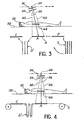
- FIGS 3 and 4 give different possibilities of such radioluminescent screens.
- FIG. 3 represents a set of radioluminescent screens such as 4 stimulable in storage position S. It is possible to perform simultaneously 3 operations: reading of a radioluminescent screen in position C, acquisition of radiation image in a position such as A, preparation of a radioluminescent screen in position P for the next x-ray.
- a storage position S ' which receives the radioluminescent screens which have acquired a radiation image, the reading being carried out at a delayed time.
- FIG. 4 shows a variant in which the radioluminescent screens are replaced by a continuous radioluminescent strip with sequential scrolling. This strip can be closed on itself thus forming a loop.
- the primary coil S is used to store blank radioluminescent screens. Between the radiation image acquisition position such as A and the reading position C, there may be a storage position S 'allowing delayed reading.
Landscapes
- Health & Medical Sciences (AREA)
- Life Sciences & Earth Sciences (AREA)
- Physics & Mathematics (AREA)
- General Physics & Mathematics (AREA)
- Medical Informatics (AREA)
- High Energy & Nuclear Physics (AREA)
- Molecular Biology (AREA)
- Engineering & Computer Science (AREA)
- Pathology (AREA)
- Animal Behavior & Ethology (AREA)
- Nuclear Medicine, Radiotherapy & Molecular Imaging (AREA)
- Optics & Photonics (AREA)
- Spectroscopy & Molecular Physics (AREA)
- Radiology & Medical Imaging (AREA)
- Biomedical Technology (AREA)
- Heart & Thoracic Surgery (AREA)
- Surgery (AREA)
- Biophysics (AREA)
- General Health & Medical Sciences (AREA)
- Public Health (AREA)
- Veterinary Medicine (AREA)
- Apparatus For Radiation Diagnosis (AREA)
- Facsimile Scanning Arrangements (AREA)
- Analysing Materials By The Use Of Radiation (AREA)
- Radiography Using Non-Light Waves (AREA)
Description
- La présente invention a pour objet un appareil d'imagerie médicale permettant notamment la tomographie longitudinale.
- Un écran radiuminescent stimulable exposé à un rayonnement comme des rayons X, des rayons a, des rayons P ou des rayons y emmagasine une partie de l'énergie du rayonnement reçu. L'image de rayonnement est donc mémorisée dans l'écran radioluminescent. Ensuite, lorsque cet écran radioluminescent stimulable est exposé à un rayonnement de stimulation, il émet un rayonnement lumineux en fonction de l'énergie de rayonnement emmagasinée. Ce rayonnement lumineux est capté par un photodétecteur qui le transforme en un signal électrique exploitable.
- On connaît de tels dispositifs de lecture d'une image de rayonnement contenue dans un écran radioluminescent stimulable, notamment par le brevet américain n° 4 239 968 du 16 décembre 1980. La stimulation de l'écran radioluminescent stimulable requiert un rayonnement de stimulation de forte énergie, c'est pourquoi la stimulation se fait en général par un faisceau laser stimulant un point de l'écran radioluminescent, ce faisceau de rayons de stimulation étant dévié par un moyen de déflexion de manière à balayer point par point tout l'écran radioluminescent stimulable.
- Les moyens de déflexion utilisés dans les dispositifs de lecture d'une image de rayonnement selon l'art connu sont le plus souvent des miroirs tournants. Il s'agit donc d'un moyen de déflexion comprenant des pièces mobiles, ce qui limite la vitesse de balayage de l'écran radioluminescent stimulable. Cette vitesse de balayage est déterminée par le temps d'accès aléatoire qui mesure la durée nécessaire au faisceau de rayons de stimulation pour passer d'un point de l'écran radioluminescent stimulable à un autre point quelconque de l'écran radioluminescent stimulable. Ce temps d'accès aléatoire est de l'ordre de 1 ms pour un faisceau de rayons de stimulation dévié par un miroir tournant. Le temps de stimulation de la totalité de l'écran radioluminescent stimulable est alors de l'ordre de la minute. En radiologie medicale ce temps de lecture n'est pas une contrainte car on a le temps de lire l'écran radioluminescent stimulable entre deux radiographies. Par contre, ce temps de lecture de l'écran radiolumimescent stimulable empêche de faire de la tomographie longitudinale où il faut prendre plusieurs radiographies rapidement, c'est-à-dire à des intervalles de l'ordre de la seconde.
- La présente invention a pour but d'améliorer le temps d'accès aléatoire à un point de l'écran radioluminescent stimulable en vue de faire, notamment, de la tomographie longitudinale.
- La présente invention consiste notamment à doter les dispositifs de lecture d'images de rayonnement d'un moyen de déflexion ne comportant pas de pièces mobiles, ce qui assure une plus grande vitesse de déflexion et une meilleure précision, donc un temps d'acces aléatoire moindre.
- L'invention a pour objet un appareil d'imagerie médicale permettant la tomographie longitudinale comprenant:
- - une surface de réception d'un patient
- - une source de rayonnement X ou y, mobile selon une direction parallèle à la surface et munie de collimateurs mobiles selon un axe parallèle à ladite surface et perpendiculaire à la direction de déplacement de la source,
- - un écran radioluminescent stimulable, mobile selon une direction parallèle à celle de la source de rayonnement et interceptant le faisceau de rayonnement ayant traversé le patient,
- - un dispositif de lecture émettant un faisceau de stimulation pour lire un écran radioluminescent stimulable contenant une image de rayonnement,
- - un photodétecteur pour recevoir l'image lumineuse émise par l'écran radioluminescent stimulé par le faisceau de stimulation,
- - des moyens de traitement du signal électrique délivré par le photodétecteur
- Selon une autre caractéristique, l'écran radioluminescent stimulable est continu.
- L'invention sera mieux comprise à la lecture de la description qui suit d'un exemple de réalisation donné à titre indicatif et non limitatif, en référence aux dessins annexés sur lesquels:
- - la figure 1 représente, vu de dessus, un dessin schématique d'un dispositif de lecture conforme à l'invention;
- - la figure 2a represente schématiquement, vu de face, un appareil de tomographie longitudinale utilisant le dispositif de lecture selon l'invention;
- - la figure 2b représente le même appareil de tomographie vu de côte;
- - les figures 3 et 4 représentent différents systèmes de mise en place d'écrans radioluminescents stimulables.
- Sur la figure 1, on a représenté un dispositif de lecture 2 d'une image de rayonnement contenue dans un écran radioluminescent 4 stimulable. Pour balayer l'écran radioluminescent 4 stimulable, il faut deux moyens de déflexion, l'un réalisant une déflexion horizontale du faisceau de rayonnement de stimulation et l'autre une déflexion verticale de ce faisceau. Pour simplifier le schéma de la figure 1, on a supposé que l'écran radioluminescent 4 stimulable était linéaire; un seul moyen de déflexion est alors nécessaire.
- Le dispositif de lecture 2 comprend une source 6 générant le faisceau de rayons de stimulation. Cette source 6 peut être un laser, par exemple un laser He-Ne, un laser à rubis, un laser à krypton ou autre. Cette source 6 sera choisie telle que la longueur d'onde de son rayonnement soit suffisamment différente de la longueur d'onde du rayonnement lumineux émis par l'écran radioluminescent 4 stimulable pour que le photorécepteur soit sensible au second rayonnement et non au premier. La mesure du rayonnement émis peut être facilitée par un filtrage adéquat.
- Le faisceau de rayons de stimulation issu de la source 6 est focalisé par une lentille 8 sur un moyen de contrôle 10 de l'intensité de la source 6. En effet, le rayonnement lumineux émis par l'écran radioluminescent 4 stimulable varie avec l'intensité du faisceau de rayons de stimulation. Il importe donc de stimuler l'écran radioluminescent 4 stimulable avec un faisceau de rayons de stimulation d'intensité constante pour avoir une image de rayonnement lumineux identique à l'image mémoire dans l'écran radioluminescent 4 stimulable.
- Ce contrôle est effectué par un détecteur 10d recevant une partie du faisceau de rayons de stimulation réfléchi par une lame semi- transparente 12 et focalisé par une lentille 14. Ce détecteur 10d est relié à un oscillateur 10c qui commande au travers d'un amplificateur 10b un modulateur 10a, par exemple de type acousto-optique. Cette boucle de contrôle du faisceau de rayons de stimulation assure une stimulation uniforme de l'écran radioluminescent 4 stimulable. Le faisceau de rayons de stimulation sortant du modulateur 10a traverse un polariseur 16 qui oriente le plan de polarisation de l'onde de stimulation dans une direction convenable pour le déflecteur 18a. Des lentilles 20, 22 et 24 sont placées entre le modulateur 10a et le déflecteur 18a; leur rôle de focalisation et de défocalisation apparaît clairement sur la figure 1. Le moyen de déflexion 18, de type acousto-optique, comprend le déflecteur 18a et un moyen de commande 18b. Le moyen de commande 18b génère un signal électrique de fréquence de l'ordre de 100 à 200 MHz, d'énergie quelques watts. Ce signal électrique appliqué sur un cristal piézoélectrique transforme cette onde électrique en une onde de pression qui traverse le déflecteur 18a, constitué par exemple d'un cristal tel que MoPb04, faisant varier son indice optique n et par conséquent déviant le faisceau de rayons de stimulation qui est ensuite focalisé par la lentille 26 sur l'écran radioluminescent 4 stimulable. Le signal électrique est bien entendu ajusté de façon que le faisceau de tayons de stimulation balaie tout l'écran radioluminescent 4 stimulable.
- Un tel dispositif de lecture, muni d'un moyen de déflexion acousto-optique, a un temps d'accès aléatoire de 10 microsecondes ou moins, 100 fois moindre que celui d'un dispositif de lecture muni d'un moyen de déflexion par miroir tournant. Ce gain de temps de lecture permet de faire de la tomographie longitudinale. Mais il peut aussi se révéler intéressant pour la lecture rapide de toute image de rayonnement.
- Les figures 2a et 2b représentent schématiquement un appareil de tomographie utilisant le dispositif selon l'invention. Cet appareil comprend une source de rayonnement 28 traversant un patient 30 placé sur une surface plane 32. Le rayonnement est reçu par l'écran radioluminescent 4 stimulable situé sous la surface plane 32. Un collimateur 34 limite la largeur du faisceau de rayonnment à la largeur de l'écran radioluminescent 4 stimulable, le terme de largeur s'appliquant aux dimensions transverses. Un collimateur 36 limite l'épaisseur du faisceau de rayonnement 38 à un trait. Ces deux collimateurs 34 et 36 sont mobiles autour d'un axe 31, visible sur la figure 2b. Par déplacement de ce collimateur 36, le faisceau de rayonnement peut se déplacer entre les limites extrêmes 40 et 42 pour balayer la longueur de l'écran radioluminescent 4 stimulable. L'appareil de tomographie comprend en outre un dispositif de lecture 2 conforme à l'invention, un photodétecteur 46 et des moyens de traitement 48. Par moyen de traitement, nous entendons tout moyen que l'homme de l'art utilise habituellement dans un tel appareil à savoir amplificateur, convertisseur analogique- numérique, mémoire, visualisation, etc...
- La tomographie longitudinale consiste à prendre des images d'un même plan sous différents angles. La coupe longitudinale est alors reconstituée par traitement numérique et combinaison des différentes images.
- La saisie d'images radiographiques pour reconstituer la coupe longitudinale 44 s'opère de la façon suivante. La source de rayonnement 28 et les deux collimateurs 34 et 36, mobiles solidairement dans le sens longitudinal comme indiqué par les flèches, sont placés dans la position, par exemple A, permettant de faire une radiographie du plan 44 sous l'angle choisi. L'écran radioluminescent 4 stimulable, mobile dans le sens logitudinal indépendamment de la source de rayonnement 28 est positionné de manière à recevoir le rayonnement issu de la source de rayonnement 28. Lorsque l'image de rayonnement est mémorisée dans l'écran radioluminescent 4 stimulable, celui-ci est déplacé en position C où il est stimulé par le dispositif de lecture 2. Le rayonnement lumineux émis capté par le photodétecteur 46 est ensuite traité par le moyen de traitement 48. La source de rayonnement 28 peut être ensuite déplacée dans une autre position telle que B et l'écran radioluminescent 4 stimulable placé en regard dans la position B correspondante pour opérer la saisie d'une autre image.
- Le temps d'attente entre deux radiographies est alors au moins égal au temps de lecture de l'écran radioluminescent 4 en position C et aux temps de transfert de A en C puis de C en B. Ce temps peut être réduit si l'on dispose de plusieurs écrans radioluminescents tels que 4 stimulables, on peut alors simultanément lire un écran radioluminescent en position C et saisir une image de rayonnement sur un écran radioluminescent en position A.
- Les figures 3 et 4 donnent différentes possibilités de tels écrans radioluminescents.
- La figure 3 représente un ensemble d'écrans radioluminescents tel que 4 stimulables en position de stockage S. On peut effectuer simultanément 3 opérations: lecture d'un écran radioluminescent en position C, acquisition d'image de rayonnement dans une position telle que A, préparation d'un écran radioluminescent en position P pour la prochaine radiographie. On peut aussi imaginer une position de stockage S' qui reçoit les écrans radioluminescents ayant acquis une image de rayonnement, la lecture se faisant en différé au moment le plus opportun.
- La figure 4 montre une variante où les écrans radioluminescents sont remplacés par une bande radioluminescente continue à défilement séquentiel. Cette bande peut être refermée sur elle-même formant ainsi une boucle. La bobine primaire S sert de stockage d'écrans radioluminescents vierges. Entre la position d'acquisition d'image de rayonnement telle que A et la position de lecture C, on peut avoir une position de stockage S' permettant une lecture différée.
ledit appareil étant caractérisé en ce qu'il comprend un ensemble d'écrans radioluminescents stimulables et en ce que le dispositif de lecture comprend un moyen de déflexion de type acousto-optique pour balayer le faisceau de stimulation sur la surface d'un écran radioluminescent stimulable.
Claims (5)
Applications Claiming Priority (2)
| Application Number | Priority Date | Filing Date | Title |
|---|---|---|---|
| FR8219228A FR2536181B1 (fr) | 1982-11-17 | 1982-11-17 | Dispositif de lecture d'une image de rayonnement contenue dans un ecran radioluminescent et appareil de tomographie comprenant ledit dispositif |
| FR8219228 | 1982-11-17 |
Publications (2)
| Publication Number | Publication Date |
|---|---|
| EP0112203A1 EP0112203A1 (fr) | 1984-06-27 |
| EP0112203B1 true EP0112203B1 (fr) | 1986-09-03 |
Family
ID=9279252
Family Applications (1)
| Application Number | Title | Priority Date | Filing Date |
|---|---|---|---|
| EP19830402191 Expired EP0112203B1 (fr) | 1982-11-17 | 1983-11-10 | Appareil d'imagerie médicale permettant la tomographie longitudinale |
Country Status (4)
| Country | Link |
|---|---|
| EP (1) | EP0112203B1 (fr) |
| JP (1) | JPS59103652A (fr) |
| DE (1) | DE3365898D1 (fr) |
| FR (1) | FR2536181B1 (fr) |
Families Citing this family (3)
| Publication number | Priority date | Publication date | Assignee | Title |
|---|---|---|---|---|
| US4816690A (en) * | 1983-12-02 | 1989-03-28 | Fuji Photo Film Co., Ltd. | Method and apparatus for radiation image recording and read-out including control of read-out in accordance with irradiation field definition |
| US4816677A (en) * | 1983-12-02 | 1989-03-28 | Fuji Photo Film Co., Ltd. | Method and apparatus for radiation image recording and read-out including data processing based on a portion of image data defined by an irradiation field stop |
| EP0181520B1 (fr) * | 1984-10-16 | 1992-04-01 | Fuji Photo Film Co., Ltd. | Dispositif pour l'enregistrement et la reproduction d'image de rayonnement |
Family Cites Families (10)
| Publication number | Priority date | Publication date | Assignee | Title |
|---|---|---|---|---|
| US3617931A (en) * | 1969-05-05 | 1971-11-02 | Bell Telephone Labor Inc | Acousto-optic devices using lead molybdate and related compounds |
| JPS538478B2 (fr) * | 1972-12-29 | 1978-03-29 | ||
| US4114987A (en) * | 1976-03-05 | 1978-09-19 | Vagi Robert J | Deflector control circuit |
| DE2719068A1 (de) * | 1977-04-28 | 1978-11-02 | Siemens Ag | Strahlendiagnostikgeraet fuer die erzeugung von schichtbildern |
| US4179100A (en) * | 1977-08-01 | 1979-12-18 | University Of Pittsburgh | Radiography apparatus |
| JPS5944333B2 (ja) * | 1978-07-12 | 1984-10-29 | 富士写真フイルム株式会社 | 放射線像変換方法 |
| JPS5618798A (en) * | 1979-07-24 | 1981-02-21 | Fuji Photo Film Co Ltd | Information recording method in radiation image record |
| JPS56104645A (en) * | 1979-12-25 | 1981-08-20 | Fuji Photo Film Co Ltd | Radiation picture treating method and its device |
| US4581535A (en) * | 1981-10-16 | 1986-04-08 | Fuji Photo Film Co., Ltd. | Method of recording X-ray image |
| CA1192674A (fr) * | 1981-10-16 | 1985-08-27 | Hisatoyo Kato | Systeme d'enregistrement et de lecture d'images par rayonnement |
-
1982
- 1982-11-17 FR FR8219228A patent/FR2536181B1/fr not_active Expired
-
1983
- 1983-11-10 DE DE8383402191T patent/DE3365898D1/de not_active Expired
- 1983-11-10 EP EP19830402191 patent/EP0112203B1/fr not_active Expired
- 1983-11-16 JP JP58215879A patent/JPS59103652A/ja active Pending
Also Published As
| Publication number | Publication date |
|---|---|
| JPS59103652A (ja) | 1984-06-15 |
| FR2536181A1 (fr) | 1984-05-18 |
| FR2536181B1 (fr) | 1985-10-11 |
| EP0112203A1 (fr) | 1984-06-27 |
| DE3365898D1 (en) | 1986-10-09 |
Similar Documents
| Publication | Publication Date | Title |
|---|---|---|
| EP0074877B1 (fr) | Système de contrôle non destructif de la structure interne d'objets | |
| EP0425333B1 (fr) | Dispositif de localisation en temps réel de sources de rayonnement | |
| Wiersma et al. | An accurate technique to record the angular distribution of backscattered light | |
| US5303710A (en) | Apparatus for imaging an object in or through a scattering medium using coherent anti-Stokes Raman scattering | |
| EP0157688B1 (fr) | Installation de radiologie à filtre compensateur | |
| EP0141724B1 (fr) | Dispositif d'asservissement pour l'alignement automatique d'un faisceau laser | |
| FR2471178A1 (fr) | Appareil de radiographie | |
| FR2623996A1 (fr) | Dispositif de surveillance du patient dans un appareil d'examen medical | |
| FR2763699A1 (fr) | Detecteur-optoelectronique | |
| FR2760833A1 (fr) | Procede et dispositif de mesure de l'epaisseur d'une couche mince par fluorescence aux rayons x | |
| FR2538240A1 (fr) | Installation a rayons x pour l'examen radiologique d'un sujet et procede pour exposer un sujet a des rayons x pendant un ou plusieurs balayages | |
| US5270853A (en) | Method and apparatus for imaging an object in or through a scattering medium by using multiple-wave mixing | |
| FR2477712A1 (fr) | Dispositif produisant un niveau de tension continue absolu avec un gain stabilise pour commander la sensibilite d'un appareil de controle par application de lumiere | |
| EP0112203A1 (fr) | Appareil d'imagerie médicale permettant la tomographie longitudinale | |
| US4943871A (en) | Image read-out and reproducing apparatus | |
| EP0600014B1 (fr) | Procede et appareil de determination de la position exacte d'une cible a l'aide d'un dispositif de reception comprenant une partie active lineaire formee d'une multiplicite d'elements discrets sensibles aux rayonnements | |
| EP0518733A1 (fr) | Procédé et dispositif de balayage pour un dispositif de prise de vue opto-électronique à grand champ et à haute résolution | |
| US3449945A (en) | Optical scanning systems for photoelectric tonometers | |
| FR2533713A1 (fr) | Dispositif de detection de la position d'un faisceau destine a un dispositif de balayage optique | |
| FR2570489A1 (fr) | Procede et dispositif pour le controle des volumes de verre apres decoupe | |
| EP0562924B1 (fr) | Dispositif de mesure de la vitesse de déplacement d'un objet | |
| US3720832A (en) | Infrared scanning system for material testing | |
| FR2674342A1 (fr) | Procede et dispositif pour concentrer sur une cible l'energie d'un faisceau de rayonnement monochromatique. | |
| FR2803916A1 (fr) | Procede et dispositif d'imagerie par rayons ionisants | |
| FR2807602A1 (fr) | Dispositif et procede de traitement de lumiere, cassette de prise d'images, module de mesure de dose et appareil de radiologie |
Legal Events
| Date | Code | Title | Description |
|---|---|---|---|
| PUAI | Public reference made under article 153(3) epc to a published international application that has entered the european phase |
Free format text: ORIGINAL CODE: 0009012 |
|
| AK | Designated contracting states |
Designated state(s): DE GB NL |
|
| 17P | Request for examination filed |
Effective date: 19841128 |
|
| GRAA | (expected) grant |
Free format text: ORIGINAL CODE: 0009210 |
|
| AK | Designated contracting states |
Kind code of ref document: B1 Designated state(s): DE GB NL |
|
| REF | Corresponds to: |
Ref document number: 3365898 Country of ref document: DE Date of ref document: 19861009 |
|
| PLBE | No opposition filed within time limit |
Free format text: ORIGINAL CODE: 0009261 |
|
| STAA | Information on the status of an ep patent application or granted ep patent |
Free format text: STATUS: NO OPPOSITION FILED WITHIN TIME LIMIT |
|
| 26N | No opposition filed | ||
| PGFP | Annual fee paid to national office [announced via postgrant information from national office to epo] |
Ref country code: NL Payment date: 19871130 Year of fee payment: 5 |
|
| PG25 | Lapsed in a contracting state [announced via postgrant information from national office to epo] |
Ref country code: GB Effective date: 19881110 |
|
| PG25 | Lapsed in a contracting state [announced via postgrant information from national office to epo] |
Ref country code: NL Effective date: 19890601 |
|
| NLV4 | Nl: lapsed or anulled due to non-payment of the annual fee | ||
| GBPC | Gb: european patent ceased through non-payment of renewal fee | ||
| PG25 | Lapsed in a contracting state [announced via postgrant information from national office to epo] |
Ref country code: DE Effective date: 19890801 |