EP0112032B1 - Safety belt emergency locking retractor - Google Patents
Safety belt emergency locking retractor Download PDFInfo
- Publication number
- EP0112032B1 EP0112032B1 EP83306854A EP83306854A EP0112032B1 EP 0112032 B1 EP0112032 B1 EP 0112032B1 EP 83306854 A EP83306854 A EP 83306854A EP 83306854 A EP83306854 A EP 83306854A EP 0112032 B1 EP0112032 B1 EP 0112032B1
- Authority
- EP
- European Patent Office
- Prior art keywords
- spool
- teeth
- frame members
- retractor according
- axis
- Prior art date
- Legal status (The legal status is an assumption and is not a legal conclusion. Google has not performed a legal analysis and makes no representation as to the accuracy of the status listed.)
- Expired
Links
Images


Classifications
-
- B—PERFORMING OPERATIONS; TRANSPORTING
- B60—VEHICLES IN GENERAL
- B60R—VEHICLES, VEHICLE FITTINGS, OR VEHICLE PARTS, NOT OTHERWISE PROVIDED FOR
- B60R22/00—Safety belts or body harnesses in vehicles
- B60R22/34—Belt retractors, e.g. reels
- B60R22/36—Belt retractors, e.g. reels self-locking in an emergency
- B60R22/405—Belt retractors, e.g. reels self-locking in an emergency responsive to belt movement and vehicle movement
Definitions
- This invention relates to an emergency locking retractor, for a vehicle safety belt, comprising a pair of mutually parallel frame members, a spool comprising a shaft for receiving a safety belt and a respective disc adjacent to each end of the shaft, each disc having uniformly spaced locking teeth on its outer periphery, the spool being mounted on the frame members in bearings arranged to permit limited movement relative to the frame members, in a direction perpendicular to the axis of rotation, into a position in which said teeth engage with complementary teeth on the frame members to inhibit rotation of the spool, the tips of the teeth on the frame members being located on a circle centred on the released position of the axis of the spool when the latter is in its released position, resilient means being arranged to bias the spool into its position of disengagement and actuating means being arranged to cause movement of the spool into its engaged position.
- a retractor of this type is disclosed in FR-A-2481604.
- the complementary teeth on the frame members are commonly symmetrical with respect to the circle on which their tips are located, each tooth having its locking face oriented at the same angle to the radial line from such tooth to the centre of such circle, which is coincident with the axis of the spool when in its released position.
- This arrangement suffers from the disadvantage that, when the spool is in its engaged position, not more than two teeth on each disc are in engagement with corresponding teeth on the frame. Consequently, the entire load imposed by the safety belt on the retractor is taken by a maximum of four teeth.
- it is necessary for both the discs and the frame members to be formed of a relatively hard material, such as hardened steel, which is both heavy and expensive.
- the present invention is concerned with the provision of a retractor which is not subject to these disadvantages.
- the locking face of each tooth facing away from the plane in which the axis of the spool moves between its engaged position and its released position is oriented at the same angle to the radial line from such tooth to the axis of the spool when in its engaged position as that between the locking face of each tooth on the discs and the corresponding radius thereof.
- all the teeth on the frame members facing towards the plane in which the axis of the spool moves have their locking faces parallel to said plane. This has the advantage that each such face is engaged by at least the tip of one of the teeth on the corresponding disc when the spool is in its engaged position.
- the troughs between adjacent teeth on the frame members lie on a circle of the same radius as the maximum radius of the spool but centred on the axis of the spool when it is in its fully engaged position. This avoids making any of the troughs unnecessarily deep since the tips of the teeth on the discs then reach the bottoms of the troughs simultaneously.
- the teeth on the frame members may be formed at the inner ends of open-ended slots in which the spool is received.
- the teeth may form part of the edge of a respective closed aperture in each frame member completely surrounding the corresponding disc.
- the frame members may comprise the side limbs of a unitary U-shaped frame.
- the frame members may be individually secured to, or may form part of, the body of a motor vehicle in which the retractor is to be used.
- an additional tooth may be provided on one or both of the frame members with its abutment face formed of a soft resilient material such as plastics and spaced angularly in advance of the abutment faces of the other teeth.
- a soft resilient material such as plastics
- the retractor illustrated in Figure 1 has a generally U-shaped frame 10, the base portion of which is provided with a hole 12 whereby the frame 10 may be secured to the body of a motor vehicle.
- the side limbs of the U-shape constitute substantially identical frame members 14 and 16 each of which contains a generally circular aperture having a respective toothed segment 18 forming part of its upper periphery.
- the bottoms of the circular apertures are enlarged by being squared-off so as to accommodate parts of the mechanism which will be described hereinafter.
- a spool 20 is mounted in the frame 10.
- the spool 20 comprises a central shaft portion 22, on which a safety belt may be wound, two toothed discs 24 and 26, for engagement with the toothed segments 18 on the frame members 14 and 16 respectively, and two projecting stub axles 28 and 30.
- the end limbs 34 and 36 project beyond the edges of the openings in the frame members 14 and 16 so as to overlap the toothed discs 24 and 26 of the spool and prevent axial displacement thereof.
- the distance bar 32 has respective hook formations 39 and 41 on its two ends which serve to retain a retractor spring cassette 42 in engagement with the outer side face of the frame member 16 and a locking mechanism cassette 43 in engagement with the outer side face of the frame member 14.
- the enclosure for the retractor spring cassette 42 comprises an end member 44, which abuts the frame member 16 and is engaged by the hook formation 39, together with a cover 46 which carries a stop (not shown) to which the outer end of a retractor spring 48 is secured.
- the inner end of the spring 48 is secured to a plastics boss 50 having a cylindrical outer surface and a slotted opening for engagement with the flattened end of the stub axle 30 of the spool 20.
- the axial length of the boss 50 is greater than the width of the spring 48 so as to be long enough for one end thereof to project into an opening in a plastics bearing plate 52 which is slidably mounted in an elongate recess 54 in the surface of the end plate 44.
- an elongate slot 56 Centrally disposed within the recess 54 is an elongate slot 56 through which project the stub axle 30 and a boss on the bearing plate 52.
- the lengths of the recess 54 and the slot 56 are such that the bearing plate 52 can slide between a position in which the teeth on the disc 26 engage with the toothed segments 18 on the end plate 16 and a position in which they are clear of such engagement.
- a spring 58 engages with a formation on the bearing plate 52 to bias it into the disengaged position.
- the locking mechanism cassette 43 is enclosed by an end plate 60, which abuts the outer face of the frame member 14 and is engaged by the hook formation 41 on the distance bar 32, together with a cover 62.
- the end plate 60 has an elongate slot 64 and a sliding bearing 66, which is spring biased away from the toothed segments 18 on the end plate 14 by a spring 68, in a similar manner to the corresponding components of the retractor spring cassette 42.
- the boss 50 is replaced by a stub axle 70 which is rigidly attached to a ratchet wheel 72, the stub axle 70 having a cylindrical outer surface for engagement in the bearing 66 and a slot for engagement with the flattened end portion of the stub axle 28 of the spool 20.
- the sliding bearing 66 is an integral part of a control member 74 which is subject to an angular bias in the belt retractor direction by an extended limb 75 of the spring 68.
- a pawl 76 is pivotally mounted on the control member 74 so that it can be moved into engagement with the teeth of the ratchet wheel 72 by a conventional ball-in-saucer inertia sensing mechanism 78 mounted on the bottom of the end plate 60.
- the control member 74 also has an elongate slot 80 which engages with a projection 82 on a blocking pawl 84 which, in turn, is pivotally mounted on a pin 86 secured to the side of the end plate 60 facing the frame member 14.
- the end plate 60 has an elongate opening 88 through which the formation 82 projects.
- Figures 2 to 5 show the locking mechanism schematically and some of the components illustrated therein have been broken away or modified as compared with Figure 1, while others have been omitted, to enable the operation of the mechanism to be seen more clearly.
- the inertia sensing mechanism 78 comprises a carrier 90, which includes a saucer for a ball 92.
- the carrier 90 is secured to the end plate 60 and has a ball follower lever 94 pivotally mounted on a projecting part thereof.
- the follower lever 94 engages with the pawl 76.
- the direction of rotation to wind the safety belt on to the spool is anti-clockwise.
- the pivot axle 96 is relieved of the load imposed on the pawl 76 during locking by a stop 98 formed as a projection of control member 74 ( Figure 1) behind the tip of the pawl 76.
- a stop 98 formed as a projection of control member 74 ( Figure 1) behind the tip of the pawl 76.
- the back of the tip of the pawl 76 engages with the stop 98 when the pawl has moved into its locking position.
- the pawl 76 is preferably a loose fit on its pivot axle 96 in order to facilitate this action.
- the locking mechanism cassette 43 also includes a belt-pull-sensitive actuating mechanism which is of conventional type and which is not shown in Figures 2 to 5.
- the belt-pull-sensitive locking mechanism consists of an inertia disc 100 which is pivotally mounted on the stub axle 70 of the ratchet wheel 72 and a pawl 102 which is pivotally mounted on a pin 104 secured to one side face of the ratchet wheel 72 adjacent to its periphery.
- the inertia disc 100 has a pin 106 which engages in a slot in the pawl 102 to cause the latter to move outwardly, if the inertia disc 100 lags behind the ratchet wheel 72, against the action of a spring 108, when the belt is being withdrawn from the spool 20. If the belt is accelerated in the withdrawal direction, the disc 100 has sufficient inertia to overcome the action of the spring 108 with the result that the pawl 102 moves outwardly into engagement with internal ratchet teeth 109 formed on a flange projecting from the control member 74 so that the latter is thereby coupled to the ratchet wheel 72. Continued withdrawal of the belt than causes angular movement of the control plate 74 and locking of the mechanism proceeds as described above with reference to Figures 4 and 5.
- the locking faces 114 of the teeth of the segments 18 which are on the left-hand side of the plane B - B are all disposed at the same angle a to the corresponding radii of this second circle at the adjacent troughs between the teeth.
- the locking faces 115, 116 and 117 of the teeth on the righthand side of the plane B - B are all parallel to this plane. The effect of this is that the locking faces 114 are all parallel to the corresponding locking faces 118 on the toothed disc 24.
- the shaft portion 22 comprises a hollow cylinder 120 having two dimetrically opposed radial webs 122 and 124 coupled to transverse webs 126 and 128 which bound a central slot extending dimetrically across the entire shaft portion 22 for receiving the inner end of the webbing of the safety belt.
- One end of the slot has a broadened portion 130 of rectangular cross-section for receiving a locking bar of T-shaped cross-section (not shown) inserted through a loop formed in the end of the webbing.
- Two central semi-circular reinforcing webs are disposed one on each side of the central slot and interconnect the cylinder 120 and the webs 122, 124 and 126.
- Respective disc portions 24 and 26 are formed on each end of the shaft portion 22.
- Each of the disc portions 24 and 26 has a circular recess 134 from which apertures communicate with the cavities within the cylindrical shaft portion 22.
- Teeth 136 are formed on the peripheries of the disc portions 24 and 26. As can be seen from Figure 9, these teeth 136 are of symmetrical trapezoidal shape with the result that the spool 20 can be inserted into the frame 10 either way round with equally satisfactory result, thereby simplifying assembly.
- Flanges 138 project outwardly beyond the teeth 136 and help to prevent axial movement of the spool 20 relative to the frame members when the spool 20 is in the locked position.
- FIG. 10 An alternative form of spool, constructed from extruded material, is shown in Figure 10.
- the toothed discs take the form of annular members 140 and 142, their outer peripheries having teeth to engage with the toothed segments 18 on the frame and their inner peripheries having teeth which engage with grooves formed from an extruded cylindrical shaft member 144.
- the shaft member 144 has a slot 146 extending along its entire length from its periphery to its centre for reception of a bar 148 which has a narrower slot 150 through which the belt is threaded and the end portions of which form the stub axles 28 and 30.
- the belt projects through a narrow slot 152 in the member 144 opposite the slot 146.
- FIG 11 illustrates an alternative frame 160 to the frame 10 illustrated in Figure 1.
- the frame 160 is also generally U-shaped, having side frame members 162 and 164 each of which carries a toothed segment 166 similar to the toothed segments 18 of Figure 1.
- the bottom part of each side frame member 162 and 164 is omitted.
- the outer end of each of the toothed segments 166 is connected to the base portion of the frame member 160 by a respective offset reinforcing portion 168 which carries a pair of downwardly extending parallel fingers 170, 172 to define open-ended slots for receiving the stub axles 28 and 30 of the spool.
- Figures 12 and 13 illustrate another alternative in which the frame itself resists axial movement of the spool.
- the frame 180 illustrated in Figure 12, is similar to the frame 10 illustrated in Figure 1 except that the basically circular opening 182 in the side members of the frame, which is centred on the axis 184 of rotation of the spool when in its released position is enlarged by a second circular portion of larger radius centred on the point 186.
- the spool 20 is replaced by a spool 188, the toothed discs 190 of which have flanges 192 projecting radially outwardly beyond their teeth 194 to a greater extent than the flanges 138 of the spool 20.
- the diameter of that part of each of the apertures of the frame which is centred on the point 186 is greater than that of the flanges 192 while the diameter of the part centred on the released position 184 of the spool axis is between that of the flanges 192 and that of the toothed portion 194. Consequently, during assembly, the spool 188 can be inserted into the frame 180 by aligning its axis with the centre 186 but, after assembly movement of the axis of the spool to the point 186 is prevented by the sliding bearing plates 52 and 66, with the result that the spool 188 is retained against axial movement relative to the frame 180.
- the resilient plastics insert 202 is always the first part of the toothed segments 18 to come into contact with the teeth of the discs 24 and 26 and therefore takes all the wear due to operation of the locking mechanism during normal acceleration, gentle braking and cornering of the vehicle in which the retractor is fitted. Under accident conditions, the insert 202 is compressed sufficiently for the remaining teeth of the segments 18 to come into engagement with the teeth of the discs 24 and 26 in order to take full crash load.
- an insert similar to the insert 202 may be provided on the frame illustrated in Figures 11 and 12. It will also be appreciated that the insert 202 can be used in conjunction with a spool having trapezoidal teeth as illustrated in Figure 9.
Description
- This invention relates to an emergency locking retractor, for a vehicle safety belt, comprising a pair of mutually parallel frame members, a spool comprising a shaft for receiving a safety belt and a respective disc adjacent to each end of the shaft, each disc having uniformly spaced locking teeth on its outer periphery, the spool being mounted on the frame members in bearings arranged to permit limited movement relative to the frame members, in a direction perpendicular to the axis of rotation, into a position in which said teeth engage with complementary teeth on the frame members to inhibit rotation of the spool, the tips of the teeth on the frame members being located on a circle centred on the released position of the axis of the spool when the latter is in its released position, resilient means being arranged to bias the spool into its position of disengagement and actuating means being arranged to cause movement of the spool into its engaged position. A retractor of this type is disclosed in FR-A-2481604.
- In this type of retractor, the complementary teeth on the frame members are commonly symmetrical with respect to the circle on which their tips are located, each tooth having its locking face oriented at the same angle to the radial line from such tooth to the centre of such circle, which is coincident with the axis of the spool when in its released position. This arrangement suffers from the disadvantage that, when the spool is in its engaged position, not more than two teeth on each disc are in engagement with corresponding teeth on the frame. Consequently, the entire load imposed by the safety belt on the retractor is taken by a maximum of four teeth. As a consequence of this, it is necessary for both the discs and the frame members to be formed of a relatively hard material, such as hardened steel, which is both heavy and expensive. The present invention is concerned with the provision of a retractor which is not subject to these disadvantages.
- According to the invention, in a retractor of the foregoing type, the locking face of each tooth facing away from the plane in which the axis of the spool moves between its engaged position and its released position is oriented at the same angle to the radial line from such tooth to the axis of the spool when in its engaged position as that between the locking face of each tooth on the discs and the corresponding radius thereof.
- Preferably, all the teeth on the frame members facing towards the plane in which the axis of the spool moves, have their locking faces parallel to said plane. This has the advantage that each such face is engaged by at least the tip of one of the teeth on the corresponding disc when the spool is in its engaged position.
- It is desirable for the troughs between adjacent teeth on the frame members lie on a circle of the same radius as the maximum radius of the spool but centred on the axis of the spool when it is in its fully engaged position. This avoids making any of the troughs unnecessarily deep since the tips of the teeth on the discs then reach the bottoms of the troughs simultaneously.
- The teeth on the frame members may be formed at the inner ends of open-ended slots in which the spool is received. However, as an alternative, the teeth may form part of the edge of a respective closed aperture in each frame member completely surrounding the corresponding disc.
- The frame members may comprise the side limbs of a unitary U-shaped frame. Alternatively, the frame members may be individually secured to, or may form part of, the body of a motor vehicle in which the retractor is to be used.
- In order to reduce wear on the teeth as the spool moves repeatedly into and out of its engaged position during normal use (i.e. not under accident conditions), an additional tooth may be provided on one or both of the frame members with its abutment face formed of a soft resilient material such as plastics and spaced angularly in advance of the abutment faces of the other teeth. On occasions when the mechanism locks but there is insufficient load to compress the plastics material to bring the faces of the other teeth into engagement with the corresponding faces of teeth on the spool, there will be no wear on these teeth. On the other hand, under accident conditions, the resilient plastics tooth is compressed and does not take any significant load.
- Embodiments of the invention will now be described, by way of example, with reference to the accompanying drawings, in which:
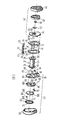
- Figure 1 is an exploded perspective view of an emergency locking retractor in accordance with the invention;
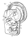
- Figure 2 is a schematic perspective diagram showing the inertia sensing mechanism in its released position;
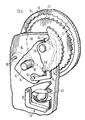
- Figure 3 is a view similar to Figure 2 showing the sensing mechanism in a preliminary locking position;
- Figure 4 is a view similar to Figures 2 and 3 showing the sensing mechanism in its fully blocked position prior to engagement of the main locking mechanism;
- Figure 5 is a view similar to Figures 2, 3 and 4 , showing the mechanism in its fully locked position;
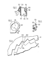
- Figure 6 is a schematic side view of one of the frame members and the corresponding locking disc showing the angular relationship between the teeth when the mechanism is in the released position.
- Figure 7 is a schematic view, similar to Figure 6, but showing the mechanism in a partially engaged position;
- Figure 8 is a longitudinal sectional view of a one-piece spool for use in the embodiment illustrated in Figure 1;
- Figure 9 is a cross-sectional view taken on the line 9-9 on Figure 8;
- Figure 10 is a perspective view of an alternative form of spool for use with the embodiment illustrated in Figure 1;
- Figure 11 is a perspective view of an alternative frame to that illustrated in Figure 1;
- Figure 12 is a side view of a further alternative frame;
- Figure 13 is a side view of one end of a modified spool for use with the frame illustrated in Figure 12; and
- Figure 14 is a fragmentary side view of part of one of the frame members and the corresponding disc of the spool, illustrating a modification to reduce tooth wear.
- The retractor illustrated in Figure 1 has a generally
U-shaped frame 10, the base portion of which is provided with ahole 12 whereby theframe 10 may be secured to the body of a motor vehicle. The side limbs of the U-shape constitute substantiallyidentical frame members respective toothed segment 18 forming part of its upper periphery. The bottoms of the circular apertures are enlarged by being squared-off so as to accommodate parts of the mechanism which will be described hereinafter. - A
spool 20 is mounted in theframe 10. Thespool 20 comprises acentral shaft portion 22, on which a safety belt may be wound, twotoothed discs toothed segments 18 on theframe members stub axles - A
distance bar 32 having perpendicularly projectingside limbs notches frame members end limbs frame members toothed discs distance bar 32 hasrespective hook formations retractor spring cassette 42 in engagement with the outer side face of theframe member 16 and alocking mechanism cassette 43 in engagement with the outer side face of theframe member 14. - The enclosure for the
retractor spring cassette 42 comprises anend member 44, which abuts theframe member 16 and is engaged by thehook formation 39, together with acover 46 which carries a stop (not shown) to which the outer end of aretractor spring 48 is secured. The inner end of thespring 48 is secured to aplastics boss 50 having a cylindrical outer surface and a slotted opening for engagement with the flattened end of thestub axle 30 of thespool 20. The axial length of theboss 50 is greater than the width of thespring 48 so as to be long enough for one end thereof to project into an opening in aplastics bearing plate 52 which is slidably mounted in anelongate recess 54 in the surface of theend plate 44. Centrally disposed within therecess 54 is an elongate slot 56 through which project thestub axle 30 and a boss on thebearing plate 52. The lengths of therecess 54 and the slot 56 are such that thebearing plate 52 can slide between a position in which the teeth on thedisc 26 engage with thetoothed segments 18 on theend plate 16 and a position in which they are clear of such engagement. Aspring 58 engages with a formation on thebearing plate 52 to bias it into the disengaged position. - The
locking mechanism cassette 43 is enclosed by anend plate 60, which abuts the outer face of theframe member 14 and is engaged by thehook formation 41 on thedistance bar 32, together with acover 62. Theend plate 60 has anelongate slot 64 and a sliding bearing 66, which is spring biased away from thetoothed segments 18 on theend plate 14 by aspring 68, in a similar manner to the corresponding components of theretractor spring cassette 42. However, in thelocking mechanism cassette 43, theboss 50 is replaced by astub axle 70 which is rigidly attached to aratchet wheel 72, thestub axle 70 having a cylindrical outer surface for engagement in thebearing 66 and a slot for engagement with the flattened end portion of thestub axle 28 of thespool 20. - The sliding bearing 66 is an integral part of a
control member 74 which is subject to an angular bias in the belt retractor direction by anextended limb 75 of thespring 68. Apawl 76 is pivotally mounted on thecontrol member 74 so that it can be moved into engagement with the teeth of theratchet wheel 72 by a conventional ball-in-saucerinertia sensing mechanism 78 mounted on the bottom of theend plate 60. Thecontrol member 74 also has anelongate slot 80 which engages with aprojection 82 on a blockingpawl 84 which, in turn, is pivotally mounted on apin 86 secured to the side of theend plate 60 facing theframe member 14. Theend plate 60 has anelongate opening 88 through which theformation 82 projects. - Figures 2 to 5 show the locking mechanism schematically and some of the components illustrated therein have been broken away or modified as compared with Figure 1, while others have been omitted, to enable the operation of the mechanism to be seen more clearly. It will be seen that the
inertia sensing mechanism 78 comprises acarrier 90, which includes a saucer for aball 92. Thecarrier 90 is secured to theend plate 60 and has a ball follower lever 94 pivotally mounted on a projecting part thereof. The follower lever 94 engages with thepawl 76. The direction of rotation to wind the safety belt on to the spool is anti-clockwise. - The operation of the locking mechanism is as follows. When any horizontal acceleration to which the retractor is subject, is below the threshold level at which actuation of the locking mechanism is required, the
ball 92 remains in the centre of its saucer and thepawl 76 is out of engagement with theratchet wheel 72, as shown in Figure 2. - Turning to Figure 3, when the above-mentioned threshold level of acceleration is exceeded, the
ball 92 is displaced to nearer the edge of its saucer, lifting thelever 94 so that thepawl 76 is moved into engagement with theratchet wheel 72. As already mentioned, theratchet wheel 72 is fast with thespool 20 and consequently any withdrawal of the safety belt from thespool 20 will cause clockwise angular movement of the ratchet wheel 72 (as viewed in Figures 2 to 5) and this angular movement is transmitted by thepawl 76 to thecontrol plate 74. As shown in Figure 4, such angular movement of thecontrol plate 74 results in the blockingpawl 84 pivoting into engagement with thetoothed disc 24 of thespool 20 so as to block angular movement of the latter about itsstub axles spool 20 pivots on the tip of the blockingpawl 84, the bearingplates slots 56 and 64 against the action of thesprings 58 and 68 (Figure 1) until the teeth of thediscs toothed segments 18 on theframe members control plate 74 has commenced, the mechanism will move into and then remain in its fully locked position until tension in the safety belt is removed, even if theball 92 has returned to its central position in its saucer. - The
pivot axle 96 is relieved of the load imposed on thepawl 76 during locking by astop 98 formed as a projection of control member 74 (Figure 1) behind the tip of thepawl 76. As can best be seen from Figure 4, the back of the tip of thepawl 76 engages with thestop 98 when the pawl has moved into its locking position. Thepawl 76 is preferably a loose fit on itspivot axle 96 in order to facilitate this action. - Reverting to Figure 1, the
locking mechanism cassette 43 also includes a belt-pull-sensitive actuating mechanism which is of conventional type and which is not shown in Figures 2 to 5. Briefly, the belt-pull-sensitive locking mechanism consists of aninertia disc 100 which is pivotally mounted on thestub axle 70 of theratchet wheel 72 and apawl 102 which is pivotally mounted on apin 104 secured to one side face of theratchet wheel 72 adjacent to its periphery. Theinertia disc 100 has apin 106 which engages in a slot in thepawl 102 to cause the latter to move outwardly, if theinertia disc 100 lags behind theratchet wheel 72, against the action of aspring 108, when the belt is being withdrawn from thespool 20. If the belt is accelerated in the withdrawal direction, thedisc 100 has sufficient inertia to overcome the action of thespring 108 with the result that thepawl 102 moves outwardly into engagement withinternal ratchet teeth 109 formed on a flange projecting from thecontrol member 74 so that the latter is thereby coupled to theratchet wheel 72. Continued withdrawal of the belt than causes angular movement of thecontrol plate 74 and locking of the mechanism proceeds as described above with reference to Figures 4 and 5. - Referring now to Figures 6 and 7, it will be seen that, although the radially inner tips of the teeth of the
segments 18 on theframe member 14 lie on a circle of radius R1 centred on theaxis 110 of thespool 20 when in its fully disengaged position, the radially outer troughs between these teeth lie on a circle of radius R2 equal to the maximum radius R3 of thedisc 24 and having itscentre 112 coincident with the axis of thespool 20 when it has moved into its fully engaged position. Moreover, the locking faces 114 of the teeth of thesegments 18 which are on the left-hand side of the plane B - B (as viewed in Figures 6 and 7), are all disposed at the same angle a to the corresponding radii of this second circle at the adjacent troughs between the teeth. On the other hand the locking faces 115, 116 and 117 of the teeth on the righthand side of the plane B - B are all parallel to this plane. The effect of this is that the locking faces 114 are all parallel to the corresponding locking faces 118 on thetoothed disc 24. Since the angle c between the plane B - B and the radial line from thecentre 112 to thetooth face 115 is equal to the angle a, thistooth face 115 is also parallel to thecorresponding locking face 118. The result is that, as thespool 20 moves into its engaged position, all of the locking faces 114 and 115 come into full face engagement with the corresponding locking faces 118 on thetoothed disc 24. At the same time, thefaces tips 119 of the corresponding teeth on the toothed disc, thesetips 119 sliding over thefaces spool 20 moves towards its fully engaged position. A similar result is achieved with thedisc 26 at the other end of the spool. As a consequence, the load carried by each individual tooth is minimised, with the result that both thediscs frame members - One consequence of the acceptability of forming the
lock locking discs entire spool 20 as a single die casting. Such a spool is shown in Figures 8 and 9. Theshaft portion 22 comprises ahollow cylinder 120 having two dimetrically opposedradial webs transverse webs 126 and 128 which bound a central slot extending dimetrically across theentire shaft portion 22 for receiving the inner end of the webbing of the safety belt. One end of the slot has a broadenedportion 130 of rectangular cross-section for receiving a locking bar of T-shaped cross-section (not shown) inserted through a loop formed in the end of the webbing. Two central semi-circular reinforcing webs, one of which can be seen at 132 in Figure 8, are disposed one on each side of the central slot and interconnect thecylinder 120 and thewebs -
Respective disc portions shaft portion 22. Each of thedisc portions circular recess 134 from which apertures communicate with the cavities within thecylindrical shaft portion 22.Teeth 136 are formed on the peripheries of thedisc portions teeth 136 are of symmetrical trapezoidal shape with the result that thespool 20 can be inserted into theframe 10 either way round with equally satisfactory result, thereby simplifying assembly.Flanges 138 project outwardly beyond theteeth 136 and help to prevent axial movement of thespool 20 relative to the frame members when thespool 20 is in the locked position. - An alternative form of spool, constructed from extruded material, is shown in Figure 10. The toothed discs take the form of
annular members toothed segments 18 on the frame and their inner peripheries having teeth which engage with grooves formed from an extrudedcylindrical shaft member 144. Theshaft member 144 has aslot 146 extending along its entire length from its periphery to its centre for reception of abar 148 which has a narrower slot 150 through which the belt is threaded and the end portions of which form thestub axles narrow slot 152 in themember 144 opposite theslot 146. - Figure 11 illustrates an
alternative frame 160 to theframe 10 illustrated in Figure 1. Theframe 160 is also generally U-shaped, havingside frame members toothed segment 166 similar to thetoothed segments 18 of Figure 1. However, the bottom part of eachside frame member toothed segments 166 is connected to the base portion of theframe member 160 by a respective offset reinforcingportion 168 which carries a pair of downwardly extendingparallel fingers stub axles spool 20 is in place, the offset reinforcingportions 168 confront the outer end faces of thetoothed discs spool 20. Movement of thestub axles fingers plates 52 and 56 of the twocassettes side members frame 10 illustrated in Figure 1, the omission of such bottom edges has no effect on the operation of the mechanism. - Figures 12 and 13 illustrate another alternative in which the frame itself resists axial movement of the spool. The
frame 180, illustrated in Figure 12, is similar to theframe 10 illustrated in Figure 1 except that the basicallycircular opening 182 in the side members of the frame, which is centred on theaxis 184 of rotation of the spool when in its released position is enlarged by a second circular portion of larger radius centred on thepoint 186. Thespool 20 is replaced by aspool 188, thetoothed discs 190 of which haveflanges 192 projecting radially outwardly beyond theirteeth 194 to a greater extent than theflanges 138 of thespool 20. The diameter of that part of each of the apertures of the frame which is centred on thepoint 186 is greater than that of theflanges 192 while the diameter of the part centred on the releasedposition 184 of the spool axis is between that of theflanges 192 and that of thetoothed portion 194. Consequently, during assembly, thespool 188 can be inserted into theframe 180 by aligning its axis with thecentre 186 but, after assembly movement of the axis of the spool to thepoint 186 is prevented by the slidingbearing plates spool 188 is retained against axial movement relative to theframe 180. - Finally, although ideally, in accordance with the invention, the teeth of the toothed segments 18 (Figure 1) and 166 (Figure 11) are so arranged that each tooth comes into engagement with a corresponding tooth of the spool simultaneously, in practice, manufacturing tolerances make this simultaneous engagement difficult to achieve with the result that one of the teeth is frequently subject to more wear than the others during normal use (i.e. under non-accident conditions). Referring to Figure 14, this difficulty can be overcome by cutting away the
bearing face 200 of one of the teeth of eachtoothed segments 18 in order to receive aninsert 202 of resilient plastics material which can conveniently be a projection formed integrally with theend members cassettes insert 202 has itsbearing surface 204 slightly proud of thesurface 200. The result is that the resilient plastics insert 202 is always the first part of thetoothed segments 18 to come into contact with the teeth of thediscs insert 202 is compressed sufficiently for the remaining teeth of thesegments 18 to come into engagement with the teeth of thediscs - It will be appreciated that an insert similar to the
insert 202 may be provided on the frame illustrated in Figures 11 and 12. It will also be appreciated that theinsert 202 can be used in conjunction with a spool having trapezoidal teeth as illustrated in Figure 9.
Claims (11)
Priority Applications (1)
| Application Number | Priority Date | Filing Date | Title |
|---|---|---|---|
| MYPI87002077A MY102600A (en) | 1982-11-20 | 1987-09-28 | Safty belt emergency locking retractor. |
Applications Claiming Priority (2)
| Application Number | Priority Date | Filing Date | Title |
|---|---|---|---|
| GB8233187 | 1982-11-20 | ||
| GB8233187 | 1982-11-20 |
Publications (4)
| Publication Number | Publication Date |
|---|---|
| EP0112032A2 EP0112032A2 (en) | 1984-06-27 |
| EP0112032A3 EP0112032A3 (en) | 1985-01-23 |
| EP0112032B1 true EP0112032B1 (en) | 1988-02-10 |
| EP0112032B2 EP0112032B2 (en) | 1991-09-18 |
Family
ID=10534405
Family Applications (1)
| Application Number | Title | Priority Date | Filing Date |
|---|---|---|---|
| EP83306854A Expired - Lifetime EP0112032B2 (en) | 1982-11-20 | 1983-11-10 | Safety belt emergency locking retractor |
Country Status (11)
| Country | Link |
|---|---|
| US (1) | US4506844A (en) |
| EP (1) | EP0112032B2 (en) |
| JP (1) | JPS59105466A (en) |
| AU (1) | AU560345B2 (en) |
| BR (1) | BR8306306A (en) |
| CA (1) | CA1225978A (en) |
| DE (1) | DE3375653D1 (en) |
| ES (1) | ES8500565A1 (en) |
| IN (1) | IN160516B (en) |
| MY (1) | MY102600A (en) |
| ZA (1) | ZA838354B (en) |
Families Citing this family (18)
| Publication number | Priority date | Publication date | Assignee | Title |
|---|---|---|---|---|
| DE3411067A1 (en) * | 1984-03-26 | 1985-10-17 | Autoflug Gmbh, 2084 Rellingen | SELF-LOCKING BELT REEL FOR SAFETY BELTS |
| DE3546227A1 (en) * | 1985-12-27 | 1987-07-02 | Trw Repa Gmbh | BELT TAPE CLAMPING DEVICE |
| DE3621622A1 (en) * | 1986-06-27 | 1988-01-21 | Trw Repa Gmbh | BELT TENSIONERS ON A SAFETY BELT REEL |
| DE3622411A1 (en) * | 1986-07-03 | 1988-01-14 | Trw Repa Gmbh | CLUTCH DEVICE FOR THE REEL SHAFT OF A SAFETY BELT REEL WITH REVERSE DEVICE |
| JPS6394070U (en) * | 1986-12-04 | 1988-06-17 | ||
| US4765559A (en) * | 1987-07-07 | 1988-08-23 | American Safety Equipment Corporation | Synchronized safety belt retractor with structural control locking means |
| US5368251A (en) * | 1989-02-24 | 1994-11-29 | Autoliv-Kolb Gmbh & Co. | Inertial reel assembly for a safety belt |
| DE4403764C2 (en) * | 1994-02-07 | 1996-06-05 | Hs Tech & Design | Automatic retractor for a seat belt |
| DE19524162A1 (en) * | 1995-07-03 | 1997-01-09 | Trw Repa Gmbh | Belt retractor for a seat belt |
| US5624087A (en) * | 1995-09-01 | 1997-04-29 | Trw Vehicle Safety Systems Inc. | Seat belt retractor with cinch mechanism |
| US5765774A (en) * | 1996-04-05 | 1998-06-16 | Takata Corporation | Seat belt retractor employing ultrasonic motor |
| JP4667600B2 (en) | 1998-10-28 | 2011-04-13 | タカタ シート ベルツ インコーポレイテッド | Reclining seat belt retractor for seat back |
| JP3645445B2 (en) * | 1999-04-09 | 2005-05-11 | 株式会社東海理化電機製作所 | Webbing take-up device |
| DE20215835U1 (en) * | 2002-10-15 | 2003-02-27 | Trw Repa Gmbh | retractor |
| JP4685674B2 (en) * | 2006-03-20 | 2011-05-18 | 株式会社東海理化電機製作所 | Webbing take-up device |
| JP5753736B2 (en) * | 2011-06-07 | 2015-07-22 | 芦森工業株式会社 | Seat belt retractor |
| DE102012005330A1 (en) * | 2012-03-19 | 2013-09-19 | Trw Automotive Gmbh | Belt retractor and method for locking a belt retractor |
| DE102012016614A1 (en) * | 2012-08-23 | 2014-02-27 | Trw Automotive Gmbh | belt reel |
Family Cites Families (6)
| Publication number | Priority date | Publication date | Assignee | Title |
|---|---|---|---|---|
| US3138405A (en) * | 1962-08-14 | 1964-06-23 | John R Hanway | Safety belt reel |
| US3237879A (en) * | 1963-10-04 | 1966-03-01 | Aircraft Mechanics | Inertia locking reel |
| DE2646238C2 (en) * | 1976-10-13 | 1989-02-23 | TRW Repa GmbH, 7077 Alfdorf | Belt retractors for vehicle seat belts |
| DE2936053A1 (en) * | 1979-09-06 | 1981-03-19 | Repa Feinstanzwerk Gmbh, 7071 Alfdorf | BELT REEL FOR VEHICLE SAFETY BELTS |
| DE3017097A1 (en) | 1980-05-03 | 1981-11-05 | Autoflug Gmbh, 2084 Rellingen | SELF-LOCKING BELT REEL FOR MOTOR VEHICLE SAFETY BELTS |
| DE3120379A1 (en) * | 1981-05-22 | 1982-12-23 | Hans-Hellmut Ing.(grad.) 2061 Sülfeld Ernst | SAFETY BELT REEL |
-
1983
- 1983-11-09 ZA ZA838354A patent/ZA838354B/en unknown
- 1983-11-09 IN IN745/DEL/83A patent/IN160516B/en unknown
- 1983-11-10 DE DE8383306854T patent/DE3375653D1/en not_active Expired
- 1983-11-10 EP EP83306854A patent/EP0112032B2/en not_active Expired - Lifetime
- 1983-11-14 AU AU21336/83A patent/AU560345B2/en not_active Ceased
- 1983-11-15 US US06/551,945 patent/US4506844A/en not_active Expired - Lifetime
- 1983-11-15 CA CA000441159A patent/CA1225978A/en not_active Expired
- 1983-11-17 BR BR8306306A patent/BR8306306A/en not_active IP Right Cessation
- 1983-11-18 ES ES527401A patent/ES8500565A1/en not_active Expired
- 1983-11-21 JP JP58219322A patent/JPS59105466A/en active Granted
-
1987
- 1987-09-28 MY MYPI87002077A patent/MY102600A/en unknown
Also Published As
| Publication number | Publication date |
|---|---|
| EP0112032B2 (en) | 1991-09-18 |
| CA1225978A (en) | 1987-08-25 |
| ES527401A0 (en) | 1984-11-01 |
| MY102600A (en) | 1992-08-17 |
| JPS59105466A (en) | 1984-06-18 |
| AU2133683A (en) | 1984-05-24 |
| BR8306306A (en) | 1984-07-03 |
| IN160516B (en) | 1987-07-18 |
| ZA838354B (en) | 1984-06-27 |
| JPH0451378B2 (en) | 1992-08-18 |
| ES8500565A1 (en) | 1984-11-01 |
| EP0112032A2 (en) | 1984-06-27 |
| AU560345B2 (en) | 1987-04-02 |
| DE3375653D1 (en) | 1988-03-17 |
| EP0112032A3 (en) | 1985-01-23 |
| US4506844A (en) | 1985-03-26 |
Similar Documents
| Publication | Publication Date | Title |
|---|---|---|
| EP0112032B1 (en) | Safety belt emergency locking retractor | |
| EP0112033B1 (en) | Safety belt emergency locking retractor | |
| US5826813A (en) | Seat belt retractor | |
| GB1602985A (en) | Safety belts for motor vehicles | |
| US4619418A (en) | Self-locking belt reel-in mechanism for safety belts | |
| US4651946A (en) | Belt retractor with belt retraction lock | |
| US4993657A (en) | Dual spring retractor | |
| EP1312517B1 (en) | Webbing retractor and method of assembling webbing retractor | |
| US4607805A (en) | Safety belt emergency locking retractor | |
| US5002236A (en) | Seat belt retractor with hollow spool | |
| US4508289A (en) | Roll-up device for safety belts | |
| EP0715577B1 (en) | Seat belt retraction mechanism | |
| EP0121256B1 (en) | Emergency lock safety belt retractor with lock-up release mechanism | |
| US4461434A (en) | Self-locking belt reeling mechanism for buckle-on safety belts in passenger-carrying vehicles | |
| US5820059A (en) | Retractor for seat belt | |
| US4687156A (en) | Lock mechanism for webbing retractor | |
| GB2156198A (en) | Safety belt emergency locking retractor | |
| US4938431A (en) | Vehicle seat belt retractor | |
| EP0669233A2 (en) | Seat belt retractor | |
| SU1346037A3 (en) | Emergency locking drawing-in arrangement for safety belt of vehcile | |
| US4103845A (en) | Take-up force eliminator for safety belt retractor | |
| US6446899B1 (en) | Seat belt retractor | |
| GB2155764A (en) | Safety belt emergency locking retractor | |
| SU931531A1 (en) | Emergency-locked drawing-in device of vehicle safety belt | |
| US4896843A (en) | Comfort mechanism with slack limit |
Legal Events
| Date | Code | Title | Description |
|---|---|---|---|
| PUAI | Public reference made under article 153(3) epc to a published international application that has entered the european phase |
Free format text: ORIGINAL CODE: 0009012 |
|
| AK | Designated contracting states |
Designated state(s): DE FR GB IT SE |
|
| PUAL | Search report despatched |
Free format text: ORIGINAL CODE: 0009013 |
|
| AK | Designated contracting states |
Designated state(s): DE FR GB IT SE |
|
| 17P | Request for examination filed |
Effective date: 19841222 |
|
| 17Q | First examination report despatched |
Effective date: 19860117 |
|
| D17Q | First examination report despatched (deleted) | ||
| GRAA | (expected) grant |
Free format text: ORIGINAL CODE: 0009210 |
|
| AK | Designated contracting states |
Kind code of ref document: B1 Designated state(s): DE FR GB IT SE |
|
| ITF | It: translation for a ep patent filed |
Owner name: ING. A. GIAMBROCONO & C. S.R.L. |
|
| REF | Corresponds to: |
Ref document number: 3375653 Country of ref document: DE Date of ref document: 19880317 |
|
| ET | Fr: translation filed | ||
| PLBI | Opposition filed |
Free format text: ORIGINAL CODE: 0009260 |
|
| 26 | Opposition filed |
Opponent name: AUTOFLUG GMBH & CO FAHRZEUGTECHNIK Effective date: 19881110 |
|
| RAP2 | Party data changed (patent owner data changed or rights of a patent transferred) |
Owner name: AUTOLIV-KOLB GMBH & CO. |
|
| PGFP | Annual fee paid to national office [announced via postgrant information from national office to epo] |
Ref country code: SE Payment date: 19901114 Year of fee payment: 8 |
|
| ITTA | It: last paid annual fee | ||
| PUAH | Patent maintained in amended form |
Free format text: ORIGINAL CODE: 0009272 |
|
| STAA | Information on the status of an ep patent application or granted ep patent |
Free format text: STATUS: PATENT MAINTAINED AS AMENDED |
|
| 27A | Patent maintained in amended form |
Effective date: 19910918 |
|
| AK | Designated contracting states |
Kind code of ref document: B2 Designated state(s): DE FR GB IT SE |
|
| PG25 | Lapsed in a contracting state [announced via postgrant information from national office to epo] |
Ref country code: SE Effective date: 19911111 |
|
| ET3 | Fr: translation filed ** decision concerning opposition | ||
| EUG | Se: european patent has lapsed |
Ref document number: 83306854.7 Effective date: 19920109 |
|
| PGFP | Annual fee paid to national office [announced via postgrant information from national office to epo] |
Ref country code: FR Payment date: 20011113 Year of fee payment: 19 |
|
| PGFP | Annual fee paid to national office [announced via postgrant information from national office to epo] |
Ref country code: GB Payment date: 20011114 Year of fee payment: 19 |
|
| PGFP | Annual fee paid to national office [announced via postgrant information from national office to epo] |
Ref country code: DE Payment date: 20011126 Year of fee payment: 19 |
|
| REG | Reference to a national code |
Ref country code: GB Ref legal event code: IF02 |
|
| PG25 | Lapsed in a contracting state [announced via postgrant information from national office to epo] |
Ref country code: GB Free format text: LAPSE BECAUSE OF NON-PAYMENT OF DUE FEES Effective date: 20021110 |
|
| PG25 | Lapsed in a contracting state [announced via postgrant information from national office to epo] |
Ref country code: DE Free format text: LAPSE BECAUSE OF NON-PAYMENT OF DUE FEES Effective date: 20030603 |
|
| GBPC | Gb: european patent ceased through non-payment of renewal fee | ||
| PG25 | Lapsed in a contracting state [announced via postgrant information from national office to epo] |
Ref country code: FR Free format text: LAPSE BECAUSE OF NON-PAYMENT OF DUE FEES Effective date: 20030731 |
|
| REG | Reference to a national code |
Ref country code: FR Ref legal event code: ST |