EP0111676B1 - Centrifugally powered pelletizing machine and method - Google Patents
Centrifugally powered pelletizing machine and method Download PDFInfo
- Publication number
- EP0111676B1 EP0111676B1 EP83110430A EP83110430A EP0111676B1 EP 0111676 B1 EP0111676 B1 EP 0111676B1 EP 83110430 A EP83110430 A EP 83110430A EP 83110430 A EP83110430 A EP 83110430A EP 0111676 B1 EP0111676 B1 EP 0111676B1
- Authority
- EP
- European Patent Office
- Prior art keywords
- rotor
- housing
- temperature
- orifices
- heat
- Prior art date
- Legal status (The legal status is an assumption and is not a legal conclusion. Google has not performed a legal analysis and makes no representation as to the accuracy of the status listed.)
- Expired
Links
- 238000000034 method Methods 0.000 title claims description 9
- 238000005453 pelletization Methods 0.000 title claims description 8
- 239000000463 material Substances 0.000 claims abstract description 18
- 239000008188 pellet Substances 0.000 claims abstract description 17
- 230000007246 mechanism Effects 0.000 claims abstract description 15
- 239000012815 thermoplastic material Substances 0.000 claims abstract description 14
- 230000004907 flux Effects 0.000 claims abstract description 10
- 230000009969 flowable effect Effects 0.000 claims abstract description 6
- 238000010438 heat treatment Methods 0.000 claims description 15
- 239000004033 plastic Substances 0.000 claims description 5
- 229920003023 plastic Polymers 0.000 claims description 5
- 230000005855 radiation Effects 0.000 claims description 5
- 238000001816 cooling Methods 0.000 claims description 3
- 230000002093 peripheral effect Effects 0.000 claims description 3
- 239000004020 conductor Substances 0.000 claims 1
- 238000009987 spinning Methods 0.000 abstract description 6
- 239000012768 molten material Substances 0.000 abstract 1
- 229920000642 polymer Polymers 0.000 description 10
- 230000000712 assembly Effects 0.000 description 4
- 238000000429 assembly Methods 0.000 description 4
- PMVSDNDAUGGCCE-TYYBGVCCSA-L Ferrous fumarate Chemical compound [Fe+2].[O-]C(=O)\C=C\C([O-])=O PMVSDNDAUGGCCE-TYYBGVCCSA-L 0.000 description 3
- XEEYBQQBJWHFJM-UHFFFAOYSA-N Iron Chemical group [Fe] XEEYBQQBJWHFJM-UHFFFAOYSA-N 0.000 description 3
- 230000033001 locomotion Effects 0.000 description 3
- 230000035699 permeability Effects 0.000 description 3
- 239000007921 spray Substances 0.000 description 3
- 238000004804 winding Methods 0.000 description 3
- 229910000831 Steel Inorganic materials 0.000 description 2
- 239000002826 coolant Substances 0.000 description 2
- 230000001419 dependent effect Effects 0.000 description 2
- 238000004519 manufacturing process Methods 0.000 description 2
- -1 polyethylene Polymers 0.000 description 2
- 238000010791 quenching Methods 0.000 description 2
- 230000000171 quenching effect Effects 0.000 description 2
- 239000010959 steel Substances 0.000 description 2
- XLYOFNOQVPJJNP-UHFFFAOYSA-N water Substances O XLYOFNOQVPJJNP-UHFFFAOYSA-N 0.000 description 2
- 238000012935 Averaging Methods 0.000 description 1
- 239000004698 Polyethylene Substances 0.000 description 1
- 239000004743 Polypropylene Substances 0.000 description 1
- 239000004793 Polystyrene Substances 0.000 description 1
- 229910000639 Spring steel Inorganic materials 0.000 description 1
- 239000000654 additive Substances 0.000 description 1
- XAGFODPZIPBFFR-UHFFFAOYSA-N aluminium Chemical compound [Al] XAGFODPZIPBFFR-UHFFFAOYSA-N 0.000 description 1
- 229910052782 aluminium Inorganic materials 0.000 description 1
- 238000004140 cleaning Methods 0.000 description 1
- 230000000295 complement effect Effects 0.000 description 1
- 238000010276 construction Methods 0.000 description 1
- 230000008878 coupling Effects 0.000 description 1
- 238000010168 coupling process Methods 0.000 description 1
- 238000005859 coupling reaction Methods 0.000 description 1
- 230000003467 diminishing effect Effects 0.000 description 1
- 230000005672 electromagnetic field Effects 0.000 description 1
- RDYMFSUJUZBWLH-UHFFFAOYSA-N endosulfan Chemical compound C12COS(=O)OCC2C2(Cl)C(Cl)=C(Cl)C1(Cl)C2(Cl)Cl RDYMFSUJUZBWLH-UHFFFAOYSA-N 0.000 description 1
- 238000005265 energy consumption Methods 0.000 description 1
- 238000001125 extrusion Methods 0.000 description 1
- 239000012530 fluid Substances 0.000 description 1
- 229910052742 iron Inorganic materials 0.000 description 1
- 238000012423 maintenance Methods 0.000 description 1
- 238000005259 measurement Methods 0.000 description 1
- 230000003287 optical effect Effects 0.000 description 1
- 229920000573 polyethylene Polymers 0.000 description 1
- 229920001155 polypropylene Polymers 0.000 description 1
- 229920002223 polystyrene Polymers 0.000 description 1
- 229920000915 polyvinyl chloride Polymers 0.000 description 1
- 239000004800 polyvinyl chloride Substances 0.000 description 1
- 238000012545 processing Methods 0.000 description 1
- 230000011514 reflex Effects 0.000 description 1
- 238000011160 research Methods 0.000 description 1
- 238000007711 solidification Methods 0.000 description 1
- 230000008023 solidification Effects 0.000 description 1
- 229910001220 stainless steel Inorganic materials 0.000 description 1
- 239000010935 stainless steel Substances 0.000 description 1
- 238000012546 transfer Methods 0.000 description 1
Images

Classifications
-
- B—PERFORMING OPERATIONS; TRANSPORTING
- B29—WORKING OF PLASTICS; WORKING OF SUBSTANCES IN A PLASTIC STATE IN GENERAL
- B29B—PREPARATION OR PRETREATMENT OF THE MATERIAL TO BE SHAPED; MAKING GRANULES OR PREFORMS; RECOVERY OF PLASTICS OR OTHER CONSTITUENTS OF WASTE MATERIAL CONTAINING PLASTICS
- B29B9/00—Making granules
- B29B9/02—Making granules by dividing preformed material
- B29B9/06—Making granules by dividing preformed material in the form of filamentary material, e.g. combined with extrusion
- B29B9/065—Making granules by dividing preformed material in the form of filamentary material, e.g. combined with extrusion under-water, e.g. underwater pelletizers
-
- B—PERFORMING OPERATIONS; TRANSPORTING
- B29—WORKING OF PLASTICS; WORKING OF SUBSTANCES IN A PLASTIC STATE IN GENERAL
- B29B—PREPARATION OR PRETREATMENT OF THE MATERIAL TO BE SHAPED; MAKING GRANULES OR PREFORMS; RECOVERY OF PLASTICS OR OTHER CONSTITUENTS OF WASTE MATERIAL CONTAINING PLASTICS
- B29B9/00—Making granules
-
- B—PERFORMING OPERATIONS; TRANSPORTING
- B29—WORKING OF PLASTICS; WORKING OF SUBSTANCES IN A PLASTIC STATE IN GENERAL
- B29C—SHAPING OR JOINING OF PLASTICS; SHAPING OF MATERIAL IN A PLASTIC STATE, NOT OTHERWISE PROVIDED FOR; AFTER-TREATMENT OF THE SHAPED PRODUCTS, e.g. REPAIRING
- B29C48/00—Extrusion moulding, i.e. expressing the moulding material through a die or nozzle which imparts the desired form; Apparatus therefor
- B29C48/25—Component parts, details or accessories; Auxiliary operations
- B29C48/36—Means for plasticising or homogenising the moulding material or forcing it through the nozzle or die
-
- B—PERFORMING OPERATIONS; TRANSPORTING
- B29—WORKING OF PLASTICS; WORKING OF SUBSTANCES IN A PLASTIC STATE IN GENERAL
- B29C—SHAPING OR JOINING OF PLASTICS; SHAPING OF MATERIAL IN A PLASTIC STATE, NOT OTHERWISE PROVIDED FOR; AFTER-TREATMENT OF THE SHAPED PRODUCTS, e.g. REPAIRING
- B29C48/00—Extrusion moulding, i.e. expressing the moulding material through a die or nozzle which imparts the desired form; Apparatus therefor
- B29C48/03—Extrusion moulding, i.e. expressing the moulding material through a die or nozzle which imparts the desired form; Apparatus therefor characterised by the shape of the extruded material at extrusion
- B29C48/04—Particle-shaped
-
- B—PERFORMING OPERATIONS; TRANSPORTING
- B29—WORKING OF PLASTICS; WORKING OF SUBSTANCES IN A PLASTIC STATE IN GENERAL
- B29C—SHAPING OR JOINING OF PLASTICS; SHAPING OF MATERIAL IN A PLASTIC STATE, NOT OTHERWISE PROVIDED FOR; AFTER-TREATMENT OF THE SHAPED PRODUCTS, e.g. REPAIRING
- B29C48/00—Extrusion moulding, i.e. expressing the moulding material through a die or nozzle which imparts the desired form; Apparatus therefor
- B29C48/03—Extrusion moulding, i.e. expressing the moulding material through a die or nozzle which imparts the desired form; Apparatus therefor characterised by the shape of the extruded material at extrusion
- B29C48/05—Filamentary, e.g. strands
Definitions
- the invention relates to a centrifugal pelletizing apparatus and to a method for forming pellets of thermoplastic material.
- EP-A-87 014 is subject matter of EP-A-87 014 (this document falls under Art. 54(3), EPC) which is directed to a method and an apparatus for forming pellets of thermoplastic materials, such as polystyrene, polyethylene, polyvinylchloride, and polypropylene, for example.
- thermoplastic materials such as polystyrene, polyethylene, polyvinylchloride, and polypropylene, for example.
- thermoplastic material including a housing, a hollow thermally conductive rotor journaled for rotation in the housing and having a series of orifices along its outer rim portion opening from the interior of the rotor for centrifugally expressing strands of heated thermoplastic material from a body of said material in a flowable state within the interior of the rotor, upon rotation of the rotor; the housing being a non-rotary housing with side walls generally parallel to the rotor sides and a peripheral wall spaced from the rim portion of the rotor; a cooling and collecting duct communicating with the housing for receiving pellets cut by the knife, mechanism for driving the rotor at a selected rate of rotation, an element for supplying material to the interior of the rotor, and a heating mechanism for introducing heat to the rotor and discloses also a method for forming pellets of thermoplastic material by centrifugally expressing strands of thermoplastic material from orifices
- the apparatus described in the aforementioned application utilizes centrifugal force to extrude the polymer through die holes in a cylindrical rotor die, operating in the range 2000 to 4000 r.p.m., and cuts the polymer strands as they are extruded into pellets which are passed to a quenching water spray.
- the compounder that incorporates additives into the polymer can increase production, as compared to previous pelletizing machines without increasing energy consumption, or can reduce energy costs without sacrificing output.
- a 22 KW unit of the type indicated is capable of the same production rates as a 55 KW extruder/underwater pelletizer, and this power savings become even more pronounced as the capacity of the units is increased.
- a heating mechanism is provided for introducing heat to the rotor in order to add heat to the material and to compensate for heat loss.
- the invention is concerned with a housing generally designated 10, within which a cooled rotor shaft is mounted, and on which a hollow rotor 11 is mounted to be driven by a suitable electric motor or the like at speeds preferably on the order of about 2000 to 4000 r.p.m.
- the rotor 11 as in the patent mentioned, includes a plurality of radially directed polymer strand expressing orifices 12, opening from the interior of the rotor through the rotor rim 13.
- a hollow sleeve 14 extends axially outwardly from the rotor side wall beyond the adjacent side wall 15 of housing 10, sleeve 14 passing freely through an opening 16 in the rotor housing side wall 15, which is mounted to be separable from the remainder of the housing so that it can function as a cover plate.
- Rotor sleeve 14 is formed with a central opening 14a, into which a stationary feed tube 17 may be inserted with clearance to feed a hot and fluid thermoplastic material at a predetermined velocity or feed rate into the hollow interior of rotor 11 opposite an impeller 18 having a flared annular surface 18a, and a front face 18b broken by communicating slots 18c extending radially at 90° intervals to form impellers which help to accelerate the flow from the zero r.p.m. at which the polymer is received, to the speed of rotation of rotor 11.
- fins 19 cruciformly arranged in the embodiment shown which are of a length, at the outlet of pipe 17, about one pipe diameter long. While the cruciform arrangement of fins 19 is presently preferred, it is also thought that other useful divisions might be 3, 5, 6 or 8.
- the dividing fins 19 divide and divert the flow in the manner indicated in Figure 5 in a uniform angular manner to avoid the creation of imbalances which would tend to cause the rotor 11 to vibrate. Without fins 19, the approximately parabolic flow profile of polymer down the feed tube 17, caused by the fact that the velocity is much higher at the center than at the wall, tends to prevent the divergence of undivided flows, and this also is a problem if the fins 19 are too long.
- the strands are, as previously, converted into pellets by a severing device generally designated 20 of the same type as in the aforementioned patent.
- the severing device 20 may include a bracket 21, upon which a pair of pulleys 22 and 23 are supported for rotation.
- the pulley 22 may be a driven pulley mounted upon the shaft 24 of a drive motor whose housing is fixedly mounted upon the bracket 21.
- Idler pulley 23 is mounted for free rotation about a shaft 25, carried on an arm 26 mounted on bracket 21, and an endless severing band 27 (which may be constructed of thin spring steel in the range 0.1 to 1.0 mm in thickness) is trained about pulleys 22 and 23 to be driven continuously in an endless path of travel.
- endless severing band 27 (which may be constructed of thin spring steel in the range 0.1 to 1.0 mm in thickness) is trained about pulleys 22 and 23 to be driven continuously in an endless path of travel.
- the lower run of endless band 27 extends generally parallely to the axis of rotor 11 and is located to extend transversely across the path of movement of the strands of plastic expressed from the rotor orifices 12.
- housing 10 includes rotor housing side plates 15 and 28, which are spaced from rotor 11 with but a slight axial clearance.
- the circumferential portion 28a ( Figure 3) of housing 10 is, however, spaced a substantial distance from the periphery of rotor 11 to allow for a substantial radial growth and projection of strands from the rotor orifices 12 and provide a chamber C between wall 28a and the rotor 11.
- the rotor housing is formed with an opening 29 ( Figure 1) to permit movement of the band 27 and band assembly into and out of operative relationship with the rotor 11.
- Member 30 which forms a continuation of rotor housing 10, comprises a pellet-passing and quenching water spray duct for receiving pellets which are severed by the band 27 and conducting them via passage 31, through a further cooling and coolant conducting system (not shown). Pellets severed by the band 27 continue in straight line motion, in a path that is generally tangential to rotor 11, and pass into the passage 31 which has coolant spray ports 32 provided therein.
- electromagnet assemblies 33 are provided at each side of the pelletizing machine, supported on rotor housing 10 in opposed alignment.
- Each assembly 33 includes, in the embodiment shown, a complement of preferably four electromagnets 34, comprising, as usual, iron cores 34a surrounded by field windings 34b.
- Each magnet assembly 33 further includes front and back magnetic field connecting plates 35 and 36 respectively, which are encased within a relatively non-conductive casing generally designated 37.
- the magnet plate 36 extends sufficiently inwardly to overlie the peripheral end of rotor housing 10, while the plate 35 is split as at 35', for purpose which will later be described, and has an abutting extension portion 35a.
- the plates or arms 35-35a and 36 are made up of very high magnetic permeability material, such as steel or iron.
- the cover 37 and rotor housing 10, however, are constructed of a relatively low permeability material, such as aluminum or 300 Series stainless steel.
- flux plates 39 which have contact with the magnet plates 35-35a and 36, and which lie in close proximity, i.e., within less than 3 mm, to the spinning rotor which itself is constructed of steel of high magnetic conductivity. In view of this proximity, we avoid the diminishing of the flux intensity across the air gaps and, because the housing 10 is constructed of a low permeability material, magnetic lines of force do not short circuit across the housing 10.
- FIGS 2 and 3 are sections through the magnet assembly 33a. It is to be understood that the magnet assembly 33b is identical, except that the magnet plates 35 and 35a are connected by a hinge 40, comprising plates 40a connected by a hinge pin 40b. With assemblies 33a and 33b being so constructed, the front wall 15 of rotor housing 10 can be pivoted outwardly about the hinge pin 40b to provide ready access to the rotor when the pelletizing operation has finished and it is desired to have access to the interior of the rotor.
- toggle clamps generally designated C, of a readily releasable variety, are provided for securing the cover 15 securely in place. This ready accessibility facilitates maintenance, cleaning, and whatever is necessary in the way of changing parts, or replacement thereof. Because the magnet assemblies are housing supported in the manner indicated, they do not create interference with either the feed supply or spindle support systems.
- the electromagnets in assembly 33a provide a magnetic field of one polarity, while the electromagnets in assembly 33b provide an electromagnetic field of opposite polarity, since it is necessary from a practical point of view that the spinning rotor pass through magnetic fields of opposite polarity. This is accomplished bywinding the coils in opposite directions at the 33a and 33b locations to create a different north-south pole arrangement at each location.
- a control of the rotor die temperature can be provided by sensing the temperature of the rotor via an infrared wave length radiation measuring optical pyrometer, and using the signal generated to control current flow to the coils 34b.
- this commercially available, noncontact radiation sensor device is shown generally at41, secured to the rotor housing wall 28.
- the lens system 41a of the device provides single lens reflex focusing along a line of sight at 41 b which is shown also in Figure 3 as directed at the rim of rotor 11 between the rows of orifices 12. It is control of the temperatures of the walls of the orifices 12 along their length which is important to provide a properly flowing polymer which does not plug the orifices, and yet, is not overheated.
- the sensor head focuses on a small spot adjacent the orifices 12, i.e., in the neighborhood of inch diameter, and is preferably sensitive to a narrow band of radiation which it integrates to an average temperature over a time period (see Figure 4).
- the sensor device 41 may be a commercially available Capintech/Heimann model obtainable from Capin- tec Instruments, Inc., of Ramsey, New Jersey, U.S.A., or Ray-O-Tube@ unit obtainable from Leeds and Northrup Company of North Wales, Pennsylvania, U.S.A., or a unit obtained from Ircon Company of Skokie, Illinois, U.S.A.
- the pyrometer electrically connects to a commercially available signal converter 42, such as a unit obtainable from Capintech, orthe Leeds and Northrup linearizer, or an Ircon indicator unit, which converts its output signal to a linear scale temperature signal, having a DC millivolt output.
- the signal from the sensor is amplified, compensated for the emissivity factor, and converted to binary form.
- the binary signal is the input to a microprocessor that linearizes the measurement and performs the computation necessary for the averaging and peak picking. The results of this computation can be displayed in temperature units and in the present system are sent to output circuits.
- a current-adjusting type temperature controller 43 such as the Leeds and Northrup Electromax V, or Ircon's proportional controller, is electrically connected with the signal converter 42 to compare the actual (input) signal with a signal representing temperature which is preset on controller 43 and provide a "differential" output signal. Then this signal is in turn fed to a DC power controller 44, which modulates the current supply flowing to the electromagnets.
- the power controller which provides the controlled current DC output to the field coils 34b from a suitable line power source may be the Model 64600 Phaser power controller manufactured commercially by Research, Inc. of Minneapolis, Minnesota, U.S.A. All of the units 41, 42, 43 and 44 are commercially available, and require no further recitation of their construction or operation than stated herein.
- the pryometer generates an electronic output signal which is dependent on the heat radiation sensed.
- This non-linear signal output is then converted to a linear temperature signal by the signal converter 42, which has a millivolt output.
- the millivolt output signal is then supplied to the temperature controller which, in turn, provides a milliamp direct current control signal, and it is this signal which outputs to the power controller 44 to modulate the supply of current to the magnet coils.
Landscapes
- Engineering & Computer Science (AREA)
- Mechanical Engineering (AREA)
- Processing And Handling Of Plastics And Other Materials For Molding In General (AREA)
- Centrifugal Separators (AREA)
Abstract
Description
- The invention relates to a centrifugal pelletizing apparatus and to a method for forming pellets of thermoplastic material.
- Such apparatus and method are subject matter of EP-A-87 014 (this document falls under Art. 54(3), EPC) which is directed to a method and an apparatus for forming pellets of thermoplastic materials, such as polystyrene, polyethylene, polyvinylchloride, and polypropylene, for example.
- This EP-document describes in detail a centrifugal pelletizing apparatus for forming pellets from thermoplastic material including a housing, a hollow thermally conductive rotor journaled for rotation in the housing and having a series of orifices along its outer rim portion opening from the interior of the rotor for centrifugally expressing strands of heated thermoplastic material from a body of said material in a flowable state within the interior of the rotor, upon rotation of the rotor; the housing being a non-rotary housing with side walls generally parallel to the rotor sides and a peripheral wall spaced from the rim portion of the rotor; a cooling and collecting duct communicating with the housing for receiving pellets cut by the knife, mechanism for driving the rotor at a selected rate of rotation, an element for supplying material to the interior of the rotor, and a heating mechanism for introducing heat to the rotor and discloses also a method for forming pellets of thermoplastic material by centrifugally expressing strands of thermoplastic material from orifices in the rim portion of a rotating hollow rotor bounded radially by a housing chamber, and severing said strands at a selected location adjacent the periphery of the rotor to form pellets, the plastic material being delivered to the rotating hollow rotor generally centrally and accelerated to approximately the speed of rotation of the rotor while the material is moving radially in the rotor to the orifices and the strands of plastic material expressed from the orifices being severed to form pellets. The apparatus described in the aforementioned application utilizes centrifugal force to extrude the polymer through die holes in a cylindrical rotor die, operating in the range 2000 to 4000 r.p.m., and cuts the polymer strands as they are extruded into pellets which are passed to a quenching water spray.
- In the system described, the compounder that incorporates additives into the polymer can increase production, as compared to previous pelletizing machines without increasing energy consumption, or can reduce energy costs without sacrificing output. For example, a 22 KW unit of the type indicated is capable of the same production rates as a 55 KW extruder/underwater pelletizer, and this power savings become even more pronounced as the capacity of the units is increased.
- In an apparatus of this type a heating mechanism is provided for introducing heat to the rotor in order to add heat to the material and to compensate for heat loss.
- It is the object of the invention to provide a control for the heat which is supplied to the system.
- This object of the invention is solved by the features of
claims 1 and 10. - Further improvements of the invention are subject matter of the subclaims.
- An embodiment of the invention is shown in the drawing in which:
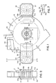
- Figure 1 is a front, side elevational view with certain parts broken away, omitted, or shown in section for the sake of convenience;
- Figure 2 is a sectional end elevational view taken on the line 2-2 of Figure 1 on an enlarged scale;
- Figure 3 is a greatly enlarged, inverse plan sectional view taken on the line 3-3 of Figure 1;
- Figure 4 is a schematic view illustrating a control system for the magnets which provide heat and maintain the described temperature of the spinning rotor;
- Figure 5 is an enlarged sectional plan view taken on the line 5-5 of Figure 1 and illustrating the manner in which the flow of polymer to the rotor housing is controlled to provide a balanced flow;
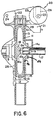
- Figure 6 is a sectional fragmentary side elevational view through the rotor housing; and
- Figure 7 is a fragmentary plan view portraying a hinge mounting for the rotor housing cover.
- It is to be understood that the aforementioned EP-document, provides an excellent description of a machine of the type to which the present improvements are directed, and that description will not be repeated in detail. Attention is, first of all, directed to Figures 1 and 6 hereof. The invention is concerned with a housing generally designated 10, within which a cooled rotor shaft is mounted, and on which a hollow rotor 11 is mounted to be driven by a suitable electric motor or the like at speeds preferably on the order of about 2000 to 4000 r.p.m. The rotor 11, as in the patent mentioned, includes a plurality of radially directed polymer
strand expressing orifices 12, opening from the interior of the rotor through therotor rim 13. - As Figure 6 particularly indicates, at the side of the rotor 11, opposite its coupling to shaft S, a hollow sleeve 14 extends axially outwardly from the rotor side wall beyond the
adjacent side wall 15 ofhousing 10, sleeve 14 passing freely through an opening 16 in the rotorhousing side wall 15, which is mounted to be separable from the remainder of the housing so that it can function as a cover plate. Rotor sleeve 14 is formed with a central opening 14a, into which astationary feed tube 17 may be inserted with clearance to feed a hot and fluid thermoplastic material at a predetermined velocity or feed rate into the hollow interior of rotor 11 opposite animpeller 18 having a flared annular surface 18a, and afront face 18b broken by communicatingslots 18c extending radially at 90° intervals to form impellers which help to accelerate the flow from the zero r.p.m. at which the polymer is received, to the speed of rotation of rotor 11. - Provided within
tube 17 arefins 19, cruciformly arranged in the embodiment shown which are of a length, at the outlet ofpipe 17, about one pipe diameter long. While the cruciform arrangement offins 19 is presently preferred, it is also thought that other useful divisions might be 3, 5, 6 or 8. - The dividing
fins 19 divide and divert the flow in the manner indicated in Figure 5 in a uniform angular manner to avoid the creation of imbalances which would tend to cause the rotor 11 to vibrate. Withoutfins 19, the approximately parabolic flow profile of polymer down thefeed tube 17, caused by the fact that the velocity is much higher at the center than at the wall, tends to prevent the divergence of undivided flows, and this also is a problem if thefins 19 are too long. - With rotation of rotor 11, thermoplastic material heated to a flowable state and thence fed from
tube 17 in divergent flow paths against theprotrusion 18, is directed and impelled radially, and then centrifugally expressed from the interior of rotor 11 throughorifices 12. The strands are, as previously, converted into pellets by a severing device generally designated 20 of the same type as in the aforementioned patent. The severingdevice 20 may include abracket 21, upon which a pair ofpulleys pulley 22 may be a driven pulley mounted upon theshaft 24 of a drive motor whose housing is fixedly mounted upon thebracket 21. Idlerpulley 23 is mounted for free rotation about ashaft 25, carried on anarm 26 mounted onbracket 21, and an endless severing band 27 (which may be constructed of thin spring steel in the range 0.1 to 1.0 mm in thickness) is trained aboutpulleys endless band 27 extends generally parallely to the axis of rotor 11 and is located to extend transversely across the path of movement of the strands of plastic expressed from therotor orifices 12. - Still referring to Figure 6, it is seen that
housing 10 includes rotorhousing side plates housing 10 is, however, spaced a substantial distance from the periphery of rotor 11 to allow for a substantial radial growth and projection of strands from therotor orifices 12 and provide a chamber C between wall 28a and the rotor 11. As previously, the rotor housing is formed with an opening 29 (Figure 1) to permit movement of theband 27 and band assembly into and out of operative relationship with the rotor 11. -
Member 30, which forms a continuation ofrotor housing 10, comprises a pellet-passing and quenching water spray duct for receiving pellets which are severed by theband 27 and conducting them viapassage 31, through a further cooling and coolant conducting system (not shown). Pellets severed by theband 27 continue in straight line motion, in a path that is generally tangential to rotor 11, and pass into thepassage 31 which hascoolant spray ports 32 provided therein. - It is necessary that the rotor 11 be heated to bring it up to the temperature desirable for extrusion and pelletizing of the particular thermoplastic material being processed, and this heating must be maintained to offset heat losses from the rotor to its surroundings to maintain the die capillaries at a temperature high enough to prevent solidification of the polymer being processed, and to transfer heat to the polymer being fed, if it is not at a high enough temperature for processing. US-A-3,483,281 discloses an eddy current heating system for accomplishing this, and the system to be described herein incorporates certain patentable improvements which greatly enhance the practicality of such a system.
- As Figures 1 and 2 disclose, electromagnet assemblies 33, generally designated 33a and 33b, are provided at each side of the pelletizing machine, supported on
rotor housing 10 in opposed alignment. Eachassembly 33 includes, in the embodiment shown, a complement of preferably fourelectromagnets 34, comprising, as usual,iron cores 34a surrounded byfield windings 34b. Eachmagnet assembly 33 further includes front and back magneticfield connecting plates - As Figure 3 indicates, the
magnet plate 36 extends sufficiently inwardly to overlie the peripheral end ofrotor housing 10, while theplate 35 is split as at 35', for purpose which will later be described, and has an abutting extension portion 35a. - The plates or arms 35-35a and 36 are made up of very high magnetic permeability material, such as steel or iron. The
cover 37 androtor housing 10, however, are constructed of a relatively low permeability material, such as aluminum or 300 Series stainless steel. Provided inslots 38, cut in thehousing side walls flux plates 39 which have contact with the magnet plates 35-35a and 36, and which lie in close proximity, i.e., within less than 3 mm, to the spinning rotor which itself is constructed of steel of high magnetic conductivity. In view of this proximity, we avoid the diminishing of the flux intensity across the air gaps and, because thehousing 10 is constructed of a low permeability material, magnetic lines of force do not short circuit across thehousing 10. Rather, they create eddy currents within the spinning rotor 11 which causes the rotor 11 to heat to the desired temperature when a direct current of a predetermined controlled amperage is applied to thewinding coils 34b, in each of theassemblies 33a and 33b. - Figures 2 and 3 are sections through the magnet assembly 33a. It is to be understood that the
magnet assembly 33b is identical, except that themagnet plates 35 and 35a are connected by ahinge 40, comprisingplates 40a connected by ahinge pin 40b. Withassemblies 33a and 33b being so constructed, thefront wall 15 ofrotor housing 10 can be pivoted outwardly about thehinge pin 40b to provide ready access to the rotor when the pelletizing operation has finished and it is desired to have access to the interior of the rotor. - Normally commercially available toggle clamps, generally designated C, of a readily releasable variety, are provided for securing the
cover 15 securely in place. This ready accessibility facilitates maintenance, cleaning, and whatever is necessary in the way of changing parts, or replacement thereof. Because the magnet assemblies are housing supported in the manner indicated, they do not create interference with either the feed supply or spindle support systems. - The electromagnets in assembly 33a provide a magnetic field of one polarity, while the electromagnets in
assembly 33b provide an electromagnetic field of opposite polarity, since it is necessary from a practical point of view that the spinning rotor pass through magnetic fields of opposite polarity. This is accomplished bywinding the coils in opposite directions at the 33a and 33b locations to create a different north-south pole arrangement at each location. Since the amount of heat generated within the spinning rotor 11 is dependent upon the number of lines of force being cut by the rotor and the flux is controlled by the current in themagnet coil windings 34b, a control of the rotor die temperature can be provided by sensing the temperature of the rotor via an infrared wave length radiation measuring optical pyrometer, and using the signal generated to control current flow to thecoils 34b. - In Figure 4 this commercially available, noncontact radiation sensor device is shown generally at41, secured to the
rotor housing wall 28. The lens system 41a of the device provides single lens reflex focusing along a line of sight at 41 b which is shown also in Figure 3 as directed at the rim of rotor 11 between the rows oforifices 12. It is control of the temperatures of the walls of theorifices 12 along their length which is important to provide a properly flowing polymer which does not plug the orifices, and yet, is not overheated. The sensor head focuses on a small spot adjacent theorifices 12, i.e., in the neighborhood of inch diameter, and is preferably sensitive to a narrow band of radiation which it integrates to an average temperature over a time period (see Figure 4). Thesensor device 41 may be a commercially available Capintech/Heimann model obtainable from Capin- tec Instruments, Inc., of Ramsey, New Jersey, U.S.A., or Ray-O-Tube@ unit obtainable from Leeds and Northrup Company of North Wales, Pennsylvania, U.S.A., or a unit obtained from Ircon Company of Skokie, Illinois, U.S.A. The pyrometer electrically connects to a commerciallyavailable signal converter 42, such as a unit obtainable from Capintech, orthe Leeds and Northrup linearizer, or an Ircon indicator unit, which converts its output signal to a linear scale temperature signal, having a DC millivolt output. - In the linearizer, the signal from the sensor is amplified, compensated for the emissivity factor, and converted to binary form. The binary signal is the input to a microprocessor that linearizes the measurement and performs the computation necessary for the averaging and peak picking. The results of this computation can be displayed in temperature units and in the present system are sent to output circuits.
- A current-adjusting
type temperature controller 43 such as the Leeds and Northrup Electromax V, or Ircon's proportional controller, is electrically connected with thesignal converter 42 to compare the actual (input) signal with a signal representing temperature which is preset oncontroller 43 and provide a "differential" output signal. Then this signal is in turn fed to aDC power controller 44, which modulates the current supply flowing to the electromagnets. The power controller, which provides the controlled current DC output to the field coils 34b from a suitable line power source may be the Model 64600 Phaser power controller manufactured commercially by Research, Inc. of Minneapolis, Minnesota, U.S.A. All of theunits - Briefly, the pryometer generates an electronic output signal which is dependent on the heat radiation sensed. This non-linear signal output is then converted to a linear temperature signal by the
signal converter 42, which has a millivolt output. The millivolt output signal is then supplied to the temperature controller which, in turn, provides a milliamp direct current control signal, and it is this signal which outputs to thepower controller 44 to modulate the supply of current to the magnet coils. - It is to be understood that the drawings and descriptive matter are in all cases to be interpreted as merely illustrative of the principles of the invention, rather than as limiting the same in any way, since it is contemplated that various changes may be made in various elements to achieve like results without departing from the scope of the appended claims.
Claims (13)
Priority Applications (1)
| Application Number | Priority Date | Filing Date | Title |
|---|---|---|---|
| AT83110430T ATE32440T1 (en) | 1982-12-13 | 1983-10-19 | DEVICE AND PROCESS FOR CENTRAL GRANULATION. |
Applications Claiming Priority (2)
| Application Number | Priority Date | Filing Date | Title |
|---|---|---|---|
| US06/448,976 US4457882A (en) | 1982-12-13 | 1982-12-13 | Centrifugally powered pelletizing machine and method |
| US448976 | 1982-12-13 |
Publications (3)
| Publication Number | Publication Date |
|---|---|
| EP0111676A2 EP0111676A2 (en) | 1984-06-27 |
| EP0111676A3 EP0111676A3 (en) | 1985-01-23 |
| EP0111676B1 true EP0111676B1 (en) | 1988-02-10 |
Family
ID=23782394
Family Applications (1)
| Application Number | Title | Priority Date | Filing Date |
|---|---|---|---|
| EP83110430A Expired EP0111676B1 (en) | 1982-12-13 | 1983-10-19 | Centrifugally powered pelletizing machine and method |
Country Status (6)
| Country | Link |
|---|---|
| US (1) | US4457882A (en) |
| EP (1) | EP0111676B1 (en) |
| JP (1) | JPS59118417A (en) |
| AT (1) | ATE32440T1 (en) |
| CA (1) | CA1208406A (en) |
| DE (1) | DE3375648D1 (en) |
Families Citing this family (2)
| Publication number | Priority date | Publication date | Assignee | Title |
|---|---|---|---|---|
| US7031693B2 (en) | 2001-09-13 | 2006-04-18 | Seamless Distribution Ab | Method and system for refilling mobile telephone prepaid phone cards via electronic distribution of refill codes |
| TWI549801B (en) * | 2009-06-18 | 2016-09-21 | 葛拉工業公司 | System for controlling cutter hub position in underfluid pelletizer |
Family Cites Families (5)
| Publication number | Priority date | Publication date | Assignee | Title |
|---|---|---|---|---|
| US3266085A (en) * | 1964-03-20 | 1966-08-16 | Dow Chemical Co | Apparatus to manufacture particulate thermoplastic resinous material |
| US3424832A (en) * | 1967-04-10 | 1969-01-28 | Dow Chemical Co | Processing of plastic |
| US3483281A (en) * | 1967-10-27 | 1969-12-09 | Dow Chemical Co | Centrifugal extrusion employing eddy currents |
| US3912799A (en) * | 1973-10-15 | 1975-10-14 | Dow Chemical Co | Centrifugal extrusion employing eddy currents |
| US4408972A (en) * | 1982-02-17 | 1983-10-11 | Baker Perkins Inc. | Centrifugal pelletizers |
-
1982
- 1982-12-13 US US06/448,976 patent/US4457882A/en not_active Expired - Lifetime
-
1983
- 1983-10-19 DE DE8383110430T patent/DE3375648D1/en not_active Expired
- 1983-10-19 AT AT83110430T patent/ATE32440T1/en not_active IP Right Cessation
- 1983-10-19 EP EP83110430A patent/EP0111676B1/en not_active Expired
- 1983-10-26 CA CA000439718A patent/CA1208406A/en not_active Expired
- 1983-12-12 JP JP58234125A patent/JPS59118417A/en active Pending
Also Published As
| Publication number | Publication date |
|---|---|
| DE3375648D1 (en) | 1988-03-17 |
| CA1208406A (en) | 1986-07-29 |
| ATE32440T1 (en) | 1988-02-15 |
| US4457882A (en) | 1984-07-03 |
| EP0111676A3 (en) | 1985-01-23 |
| EP0111676A2 (en) | 1984-06-27 |
| JPS59118417A (en) | 1984-07-09 |
Similar Documents
| Publication | Publication Date | Title |
|---|---|---|
| US3521325A (en) | Inductively heated extrusion die | |
| US20080308160A1 (en) | Device including inductively heatable fluid retainment region, and method | |
| US3912799A (en) | Centrifugal extrusion employing eddy currents | |
| SE421966B (en) | PROCEDURE AND DEVICE FOR REGULATING TEMPERATURE VOLTAGES IN A CASE SHEET | |
| US4457882A (en) | Centrifugally powered pelletizing machine and method | |
| US3483281A (en) | Centrifugal extrusion employing eddy currents | |
| CN1018539B (en) | Bushing balance controller | |
| US7271370B2 (en) | Yarn guiding godet with magnetic bearings | |
| CA1179814A (en) | Centrifugal pelletizers and methods of centrifugally pelletizing | |
| CN210429460U (en) | Tachometer magnetic ring magnetizing device for mask production equipment | |
| JP6360419B2 (en) | 2-roll kneader | |
| EP1130336A2 (en) | High efficiency fluid heating apparatus | |
| Ralchev et al. | Thermal control of filament supply in FFF/FDM 3D printing technology | |
| JP2002326269A (en) | Method and system for producing films from thermoplastic synthetic resins | |
| US5235151A (en) | Induction-heated godet | |
| US4412964A (en) | Centrifugal pelletizing systems and process | |
| EP0087014A1 (en) | Improvements in centrifugal pelletizers and methods of centrifugally pelletizing | |
| JP2001241858A (en) | Guide tube structure for electromagnetic flux concentration | |
| FI90507C (en) | Method for monitoring the solidification process in continuous continuous casting | |
| CN221529934U (en) | Centrifugal microchannel cooling device | |
| CN217434956U (en) | Injection molding machine feed cylinder heating structure | |
| EP1161577B1 (en) | Draft unit for synthetic fibers | |
| SU1177168A1 (en) | Extruder for processing polymeric materials | |
| JPH0560536B2 (en) | ||
| CN108085820B (en) | Electrically heatable godet roller and method for electrically heating a godet roller |
Legal Events
| Date | Code | Title | Description |
|---|---|---|---|
| PUAI | Public reference made under article 153(3) epc to a published international application that has entered the european phase |
Free format text: ORIGINAL CODE: 0009012 |
|
| AK | Designated contracting states |
Designated state(s): AT CH DE FR GB IT LI |
|
| PUAL | Search report despatched |
Free format text: ORIGINAL CODE: 0009013 |
|
| AK | Designated contracting states |
Designated state(s): AT CH DE FR GB IT LI |
|
| 17P | Request for examination filed |
Effective date: 19850712 |
|
| 17Q | First examination report despatched |
Effective date: 19860704 |
|
| GRAA | (expected) grant |
Free format text: ORIGINAL CODE: 0009210 |
|
| AK | Designated contracting states |
Kind code of ref document: B1 Designated state(s): AT CH DE FR GB IT LI |
|
| REF | Corresponds to: |
Ref document number: 32440 Country of ref document: AT Date of ref document: 19880215 Kind code of ref document: T |
|
| REF | Corresponds to: |
Ref document number: 3375648 Country of ref document: DE Date of ref document: 19880317 |
|
| ITF | It: translation for a ep patent filed | ||
| ET | Fr: translation filed | ||
| PLBE | No opposition filed within time limit |
Free format text: ORIGINAL CODE: 0009261 |
|
| STAA | Information on the status of an ep patent application or granted ep patent |
Free format text: STATUS: NO OPPOSITION FILED WITHIN TIME LIMIT |
|
| 26N | No opposition filed | ||
| PG25 | Lapsed in a contracting state [announced via postgrant information from national office to epo] |
Ref country code: GB Effective date: 19891019 Ref country code: AT Effective date: 19891019 |
|
| PG25 | Lapsed in a contracting state [announced via postgrant information from national office to epo] |
Ref country code: LI Effective date: 19891031 Ref country code: CH Effective date: 19891031 |
|
| GBPC | Gb: european patent ceased through non-payment of renewal fee | ||
| PG25 | Lapsed in a contracting state [announced via postgrant information from national office to epo] |
Ref country code: FR Effective date: 19900629 |
|
| REG | Reference to a national code |
Ref country code: CH Ref legal event code: PL |
|
| PG25 | Lapsed in a contracting state [announced via postgrant information from national office to epo] |
Ref country code: DE Effective date: 19900703 |
|
| REG | Reference to a national code |
Ref country code: FR Ref legal event code: ST |