EP0111596A1 - Furniture assemblies having wiring enclosures - Google Patents
Furniture assemblies having wiring enclosures Download PDFInfo
- Publication number
- EP0111596A1 EP0111596A1 EP82306362A EP82306362A EP0111596A1 EP 0111596 A1 EP0111596 A1 EP 0111596A1 EP 82306362 A EP82306362 A EP 82306362A EP 82306362 A EP82306362 A EP 82306362A EP 0111596 A1 EP0111596 A1 EP 0111596A1
- Authority
- EP
- European Patent Office
- Prior art keywords
- slot
- cover
- furniture assembly
- cover member
- bristles
- Prior art date
- Legal status (The legal status is an assumption and is not a legal conclusion. Google has not performed a legal analysis and makes no representation as to the accuracy of the status listed.)
- Ceased
Links
Images

Classifications
-
- A—HUMAN NECESSITIES
- A47—FURNITURE; DOMESTIC ARTICLES OR APPLIANCES; COFFEE MILLS; SPICE MILLS; SUCTION CLEANERS IN GENERAL
- A47B—TABLES; DESKS; OFFICE FURNITURE; CABINETS; DRAWERS; GENERAL DETAILS OF FURNITURE
- A47B21/00—Tables or desks for office equipment, e.g. typewriters, keyboards
- A47B21/06—Tables or desks for office equipment, e.g. typewriters, keyboards characterised by means for holding, fastening or concealing cables
-
- H—ELECTRICITY
- H02—GENERATION; CONVERSION OR DISTRIBUTION OF ELECTRIC POWER
- H02G—INSTALLATION OF ELECTRIC CABLES OR LINES, OR OF COMBINED OPTICAL AND ELECTRIC CABLES OR LINES
- H02G3/00—Installations of electric cables or lines or protective tubing therefor in or on buildings, equivalent structures or vehicles
- H02G3/02—Details
- H02G3/04—Protective tubing or conduits, e.g. cable ladders or cable troughs
- H02G3/0437—Channels
- H02G3/045—Channels provided with perforations or slots permitting introduction or exit of wires
-
- A—HUMAN NECESSITIES
- A47—FURNITURE; DOMESTIC ARTICLES OR APPLIANCES; COFFEE MILLS; SPICE MILLS; SUCTION CLEANERS IN GENERAL
- A47B—TABLES; DESKS; OFFICE FURNITURE; CABINETS; DRAWERS; GENERAL DETAILS OF FURNITURE
- A47B21/00—Tables or desks for office equipment, e.g. typewriters, keyboards
- A47B21/06—Tables or desks for office equipment, e.g. typewriters, keyboards characterised by means for holding, fastening or concealing cables
- A47B2021/066—Tables or desks for office equipment, e.g. typewriters, keyboards characterised by means for holding, fastening or concealing cables with power or communication connection interface
Definitions
- This invention relates to wiring enclosures and, more particularly, to a furniture assembly wiring enclosure having a cover which is generally flush with the surface of the furniture.
- the wiring enclosure should preferably include easily accessible electrical outlets so that wires passing into the enclosure may be readily connected to a power source.
- FIG. 1 Another approach is to construct a desk having a wiring enclosure integrally incorporated therein.
- An example showing this construction is US-A-3,883,202.
- Electrical outlets are located in the.bottom of the trough, and a longitudinal slot in the front vertical face of the trough extends into the trough from the rear edge of the desk top.
- the slot and a portion of the trough extend above at least parts of the desk top so that the entire assembly has a somewhat unsightly appearance.
- the enclosure is not entirely covered so that one may easily see into the wire enclosure, adding to the unsightliness of the assembled product.
- electrical outlets are provided in the trough, these outlets are somewhat inaccessible because they are located at the bottom of the trough. A person obtaining access to the outlets would have to lean over the entire desk top in order to look downwardly into the trough to make electrical connections.
- a furniture assembly comprises a wiring raceway having a slot opening adjacent a surface area of the assembly, and means for flexibly closing the slot, characterised in that the closing means comprises a plurality of flexible bristles in a brush-like configuration, the bristles being retained in retaining means and extending from the retaining means to one edge of the slot to completely cover the slot while permitting a wire extending through the slot to be pulled longitudinally along the slot.
- a furniture assembly has a surface with a slot extending through a portion thereof, the slot having first and second sides, a wiring raceway adjacent said slot, said slot communicating with said raceway, and means for covering said slot, characterised in that said covering means comprises a generally rectangularly shaped, planar cover member having first and second edges, said cover member being mounted in said slot with the distance between said first and second edges being less than the distance between said first and second sides thereby providing a space between said second edge and said second side of said slot through and along which an electrical wire can extend and be pulled; said cover member is movable to provide access into said raceway; and a flexible cover means flexibly covers the said space between said second edge and said second side of said slot whereby the wire can be pulled through and along said opening when when the said cover is in closed position.
- a wire enclosure for a furniture assembly should be constructed so as to be flush with any exterior surfaces of the assembly.
- Such a wire enclosure should be unobtrusive and should not detract from the overall appearance of the furniture.
- any slot extending into the wire enclosure should be covered with an aesthetically pleasing, flexible cover.
- the interior of the wire enclosure assembly should not normally be seen, but wires should still be able to be passed through the cover.
- the cover should blend in with the furniture surface.
- the enclosure should include an easily accessible power source connection so that wires in the enclosure may be readily connected to the power source.
- brushes have been used as sealing devices in other fields such as windows (US-A-4,037,378 and US-A-4,195,681) and animal exits (US-A-2,778,417), brushes have not been used as a sealing means for wire enclosures or indeed furniture assembly components of any type.
- a brush cover enables the wire enclosure to be sealed in an aesthetically pleasing manner.
- the brush provides a richer look than other types of sealing means, such as plastic strips.
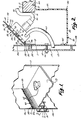
- FIG. 1 One environment in which the wiring enclosure of the invention may be used is a modular furniture assembly as shown in Figure 1.
- This assembly is of the type.which includes.two side.panels, one identified by reference numeral 17 and the other not shown. Between these side panels is mounted a working surface or desk top 13.
- a rear panel structure 2 formed by upper and lower panels 10a and lOb and an energy core 19 consisting of an energy core housing 12 and a cover plate 11 extend between the side panels at the rear of desk top 13.
- This rear panel structure 2 is supported by.a wall panel support structure (not shown).
- a wiring enclosure 1 is mounted at the rear portion of the desk top 13 between the rear edge 18 of the desk top 13 and the rear panel structure 2.
- This assembly includes a raceway or well 80 mounted under the opening or slot formed between the rear edge 18 and the rear panel structure 2, a cover assembly 20 pivotally'mounted on the rear panel structure 2, and the energy core housing 12 in which the electrical means for supplying power to the cover assembly 20, as will be disclosed hereinafter, is located.
- the cover assembly 20 includes a hinge plate 21, a cover 22, a brush 40 secured to the free edge of the cover 22, and an outlet assembly 60.
- the hinge plate 21 is secured to either the upper panel lOa or the cover plate 11 using hinge screws 25 so that the plate 21 is located substantially opposite the .rear edge 18.
- Hingedly mounted to the plate 21 is the cover 22. Ribs 23.run the full length of the underside of the cover 22 to provide additional strength. Both the hinge plate 21.and cover 22-are preferably extruded from aluminium.
- Cover-veneer 24 is applied to the upper surface of the cover 22 and selected to match the desk veneer 14 so that a coordinated appearance is achieved.
- a hinge 29, shown in more detail in Figure 6, is continuous and runs the full length of the cover 22.
- the male portion of the hinge 29 comprises a bulbous flange 30 which extends outwardly and upwardly from the hinge plate 21, the enlarged portion of the bulb providing the hinge axis.
- the cover 22 is hingedly mounted on the bulbous flange 30 by the combination of a raised rear edge 32 and a hinge flange 31 which extend away from cover 22 and around the bulbous flange 30. Movement of the cover 22 is stopped in the upward direction when the rear raised edge 32 abuts an upper surface 33 on the hinge plate 21 and in the downward direction when the hinge flange 31 abuts a forward facing surface 34 on the hinge plate.
- the brush 40 extends along substantially the entire length of the cover 22. It comprises a plurality of bristles 41 secured in a brush-like arrangement by a pinch plate 42.
- the pinch plate 42 is an elongated member made of a pliable material and generally U-shaped in cross section.
- the bristles 41 are secured by placing them within the U-shaped pinch plate 42 and clamping the same shut entrapping the bristles 41.
- This brush is similar to brushes found on the beater bar of a suction cleaner. Bristles 41 engage the rear edge 18 of the desk top when the cover 22 is completely closed, as shown in Figure 3.
- the brush 40 is mounted on the cover 22 by means of a brush channel 50 which runs substantially the entire length of the cover 22.
- the brush channel 50 is defined by a flange 53 which extends forwardly and then downwardly from the cover 22 and a flange 51 which extends forwardly and then upwardly of the cover 22. This provides a channel, the interior of which is wider than the space between the retaining edges 52 and 54 of the flanges 51 and 53, respectively; whereby brush 40 is retained within the channel 50.
- the outlet assembly 60 comprises a housing 61, outlets 62 located therein, and power cord 65.
- Outlets 62 are generally of a conventional type providing 240 volt, .50 Hertz electrical current but other standard voltages and frequencies could be employed.
- Outlets 62 are conventionally wired (not shown) to the power cord 65 which extends from the housing 61 through the cover plate 11 to a power source connection (not shown) located within the energy core 19.
- bolts 63 Secured within the upper surface of the housing 61 are bolts 63 having bolt heads 64.
- the bolts 63 extend away from the housing 61 so that the bolt heads 64 are located somewhat above the housing 61.
- the outlet assembly 60 is slidably mounted on the undersurface of the cover 22 by positioning the bolt heads 64 within a bolt channel 71 which runs substantially the entire length of the undersurface of the cover 22.
- the bolt channel 71 is defined by two adjacent ribs 23 and opposing bolt flanges 70 which extend towards each other from the adjacent ribs. Consequently, the bolt channel 71 is generally C-shaped in cross section, securing the bolt heads 64 therein. When mounted in this manner, the outlet assembly 60 may be slid along the full length of the cover 22.
- the raceway or well 80 formed by the flanges 82 and 83 is generally L-shaped in cross section and extends substantially the entire length of the desk top 13.
- An attaching flange 84 extends forwardly from the upper edge of the flange 82, and a flange 85 extends upwardly from the rear edge of the horizontal flange 83.
- the attaching flange 84 is secured to the undersurface of the desk top 13 using screws 81.
- the exact mounting location is chosen so that the flange 85 abuts the mounting plate ll.
- the raceway 80 houses the wires within the enclosure to prevent them from sagging down where they can be seen below the desk top 13.
- the raceway 80 is preferably extruded from plastic.
- the desk top 13 and the cover 22 then provide a uniform planar surface interrupted only by the brush 40.
- the wire 90 extending from the electrical plug 91 passes through the brush 40 and on to the desk top 13 where the electrical device is located. Any extra or loose wire between the device and the brush 40 is then pushed into the wire enclosure to further clean up the appearance of. the desk top.
- the wire 90 may be moved along the entire length of the brush 40 with the cover 22 fully closed. Therefore, devices may be repositioned on the desk top 13 and their associated cords may be slid along the brush 40.
- a plurality of electrical appliances could be attached in the manner described herein. Furthermore, telephone wires could also be run into the wiring enclosure if suitable connection means are provided therein.
- a wiring enclosure 100 extends between the side panels and is mounted on the rear panel structure 2 by securing an attaching plate 101 thereto.
- a desk top flange 102 extends forwardly from the lower edge of the attaching plate 101 and engages the undersurface of the desk top 13.
- Extending forwardly and then downwardly from the upper edge of the attaching plate 101 is a brush support flange 103 which is generally L-shaped in cross section.
- the brush support flange 103 is located above the desk top 13 defining a slot therebetween through and along which wires can extend-and be pulled.
- a brush 104 extends downwardly from the brush support flange 103 and engages the desk top 13 flexibly covering the slot.
- the wiring enclosure could be mounted within a slot in the upper panel 10a and open forwardly. Alternatively, the enclosure could be installed on a desk top or credenza having no adjacent wall panel.
Landscapes
- Engineering & Computer Science (AREA)
- Architecture (AREA)
- Civil Engineering (AREA)
- Structural Engineering (AREA)
- Tables And Desks Characterized By Structural Shape (AREA)
Abstract
Description
- This invention relates to wiring enclosures and, more particularly, to a furniture assembly wiring enclosure having a cover which is generally flush with the surface of the furniture.
- As evidenced.by,the scope of the prior art, a need currently exists for an aesthetically pleasing, flexibly covered wiring enclosure for furniture assemblies so that the interior of the wiring enclosure cannot normally be seen while wires can still pass . through the flexible cover. The wiring enclosure should preferably include easily accessible electrical outlets so that wires passing into the enclosure may be readily connected to a power source.
- Although wiring enclosures have been designed for use on furniture assemblies, these devices are subject to serious drawbacks. One approach includes an elongated tubular enclosure having both a longitudinal slot through which wires can be passed and a flexible plastic strip covering the slot. The enclosure is secured to the rear edge of the desk top so that the opening extends above the desk top and faces forward. An example is described in US-A-4,094,561. This device has several disadvantages. First, because the mounted device extends above the desk top, it is unsightly and does not blend in with the desk top. Second, the plastic wiper strip which is used as a cover for the longitudinal slot has a cheap appearance and consequently is unsuitable for installation on high quality furniture. Third, absolutely no provision is made for connecting wires within the enclosure to a power source. Consequently, electrical connections would have to be made with a power source away from the desk top.
- Another approach is to construct a desk having a wiring enclosure integrally incorporated therein. An example showing this construction is US-A-3,883,202. Electrical outlets are located in the.bottom of the trough, and a longitudinal slot in the front vertical face of the trough extends into the trough from the rear edge of the desk top. However, the slot and a portion of the trough extend above at least parts of the desk top so that the entire assembly has a somewhat unsightly appearance. Second, the enclosure is not entirely covered so that one may easily see into the wire enclosure, adding to the unsightliness of the assembled product. Finally, although electrical outlets are provided in the trough, these outlets are somewhat inaccessible because they are located at the bottom of the trough. A person obtaining access to the outlets would have to lean over the entire desk top in order to look downwardly into the trough to make electrical connections.
- According to one aspect of the present invention, a furniture assembly comprises a wiring raceway having a slot opening adjacent a surface area of the assembly, and means for flexibly closing the slot, characterised in that the closing means comprises a plurality of flexible bristles in a brush-like configuration, the bristles being retained in retaining means and extending from the retaining means to one edge of the slot to completely cover the slot while permitting a wire extending through the slot to be pulled longitudinally along the slot.
- According to another aspect of the present invention, a furniture assembly has a surface with a slot extending through a portion thereof, the slot having first and second sides, a wiring raceway adjacent said slot, said slot communicating with said raceway, and means for covering said slot, characterised in that said covering means comprises a generally rectangularly shaped, planar cover member having first and second edges, said cover member being mounted in said slot with the distance between said first and second edges being less than the distance between said first and second sides thereby providing a space between said second edge and said second side of said slot through and along which an electrical wire can extend and be pulled; said cover member is movable to provide access into said raceway; and a flexible cover means flexibly covers the said space between said second edge and said second side of said slot whereby the wire can be pulled through and along said opening when when the said cover is in closed position.
- By constructing the furniture assembly in accordance with the present invention, it is possible to meet the following criteria. In view of the problems and drawbacks of the prior art, a wire enclosure for a furniture assembly should be constructed so as to be flush with any exterior surfaces of the assembly. Such a wire enclosure should be unobtrusive and should not detract from the overall appearance of the furniture. Second, any slot extending into the wire enclosure should be covered with an aesthetically pleasing, flexible cover. The interior of the wire enclosure assembly should not normally be seen, but wires should still be able to be passed through the cover. The cover should blend in with the furniture surface. Finally, the enclosure should include an easily accessible power source connection so that wires in the enclosure may be readily connected to the power source.
- Although brushes have been used as sealing devices in other fields such as windows (US-A-4,037,378 and US-A-4,195,681) and animal exits (US-A-2,778,417), brushes have not been used as a sealing means for wire enclosures or indeed furniture assembly components of any type. A brush cover enables the wire enclosure to be sealed in an aesthetically pleasing manner. The brush provides a richer look than other types of sealing means, such as plastic strips.
- The invention may be carried into practice in various ways but one piece of furniture incorporating a wiring enclosure assembly embodying the invention and one possible modification will now be described by way of example with reference to the accompanying drawings, in which:
- Figure 1 is a fragmentary perspective -view of a modular furniture assembly with the wiring enclosure installed and the cover fully open;
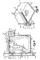
- Figure 2 is a fragmentary cross-sectional view taken along line II-II of Figure 1 with the cover partially open;
- Figure 3 is a fragmentary cross-sectional view similar to Figure 2 with the cover fully closed;
- Figure 4 is a fragmentary perspective view of a modular furniture assembly with an alternative wiring enclosure installed;
- Figure.5 is a partial, enlarged, perspective view of the structure for mounting the bristles on the cover of the assembly shown in Figures 1 to 3; and
- Figure 6 is a partial, enlarged, perspective view of the cover hinge used in the assembly shown in Figures 1 to 3.
- One environment in which the wiring enclosure of the invention may be used is a modular furniture assembly as shown in Figure 1. This assembly is of the type.which includes.two side.panels, one identified by
reference numeral 17 and the other not shown. Between these side panels is mounted a working surface ordesk top 13. A rear panel structure 2 formed by upper andlower panels 10a and lOb and anenergy core 19 consisting of anenergy core housing 12 and a cover plate 11 extend between the side panels at the rear ofdesk top 13. This rear panel structure 2 is supported by.a wall panel support structure (not shown). - A wiring enclosure 1 is mounted at the rear portion of the
desk top 13 between therear edge 18 of thedesk top 13 and the rear panel structure 2. This assembly includes a raceway or well 80 mounted under the opening or slot formed between therear edge 18 and the rear panel structure 2, acover assembly 20 pivotally'mounted on the rear panel structure 2, and theenergy core housing 12 in which the electrical means for supplying power to thecover assembly 20, as will be disclosed hereinafter, is located. - The
cover assembly 20 includes ahinge plate 21, acover 22, abrush 40 secured to the free edge of thecover 22, and anoutlet assembly 60. Thehinge plate 21 is secured to either the upper panel lOa or the cover plate 11 usinghinge screws 25 so that theplate 21 is located substantially opposite the .rear edge 18. Hingedly mounted to theplate 21 is thecover 22. Ribs 23.run the full length of the underside of thecover 22 to provide additional strength. Both the hinge plate 21.and cover 22-are preferably extruded from aluminium. Cover-veneer 24 is applied to the upper surface of thecover 22 and selected to match thedesk veneer 14 so that a coordinated appearance is achieved. - A
hinge 29, shown in more detail in Figure 6, is continuous and runs the full length of thecover 22. The male portion of thehinge 29 comprises abulbous flange 30 which extends outwardly and upwardly from thehinge plate 21, the enlarged portion of the bulb providing the hinge axis. Thecover 22 is hingedly mounted on thebulbous flange 30 by the combination of a raisedrear edge 32 and ahinge flange 31 which extend away fromcover 22 and around thebulbous flange 30. Movement of thecover 22 is stopped in the upward direction when the rear raisededge 32 abuts anupper surface 33 on thehinge plate 21 and in the downward direction when thehinge flange 31 abuts a forward facingsurface 34 on the hinge plate. - The
brush 40 extends along substantially the entire length of thecover 22. It comprises a plurality of bristles 41 secured in a brush-like arrangement by apinch plate 42. Thepinch plate 42 is an elongated member made of a pliable material and generally U-shaped in cross section. The bristles 41 are secured by placing them within the U-shapedpinch plate 42 and clamping the same shut entrapping the bristles 41. This brush is similar to brushes found on the beater bar of a suction cleaner. Bristles 41 engage therear edge 18 of the desk top when thecover 22 is completely closed, as shown in Figure 3. - As-best disclosed in Figure 5, the
brush 40 is mounted on thecover 22 by means of abrush channel 50 which runs substantially the entire length of thecover 22. Thebrush channel 50 is defined by aflange 53 which extends forwardly and then downwardly from thecover 22 and aflange 51 which extends forwardly and then upwardly of thecover 22. This provides a channel, the interior of which is wider than the space between theretaining edges 52 and 54 of theflanges brush 40 is retained within thechannel 50. - The
outlet assembly 60 comprises ahousing 61,outlets 62 located therein, andpower cord 65.Outlets 62 are generally of a conventional type providing 240 volt, .50 Hertz electrical current but other standard voltages and frequencies could be employed.Outlets 62 are conventionally wired (not shown) to thepower cord 65 which extends from thehousing 61 through the cover plate 11 to a power source connection (not shown) located within theenergy core 19. - Secured within the upper surface of the
housing 61 arebolts 63 having bolt heads 64. Thebolts 63 extend away from thehousing 61 so that the bolt heads 64 are located somewhat above thehousing 61. - The
outlet assembly 60 is slidably mounted on the undersurface of thecover 22 by positioning the bolt heads 64 within abolt channel 71 which runs substantially the entire length of the undersurface of thecover 22. Thebolt channel 71 is defined by twoadjacent ribs 23 and opposingbolt flanges 70 which extend towards each other from the adjacent ribs. Consequently, thebolt channel 71 is generally C-shaped in cross section, securing the bolt heads 64 therein. When mounted in this manner, theoutlet assembly 60 may be slid along the full length of thecover 22. - The raceway or well 80 formed by the
flanges desk top 13. An attachingflange 84 extends forwardly from the upper edge of theflange 82, and aflange 85 extends upwardly from the rear edge of thehorizontal flange 83. The attachingflange 84 is secured to the undersurface of thedesk top 13 usingscrews 81. The exact mounting location is chosen so that theflange 85 abuts the mounting plate ll. Theraceway 80 houses the wires within the enclosure to prevent them from sagging down where they can be seen below thedesk top 13. Theraceway 80 is preferably extruded from plastic. - When one is using an electrical device (not shown) on the
desk top 13 and desires to connect it to a power source, one pulls thecover 22 into the fully open position as shown in Figure 1. Theoutlet assembly 60 withoutlets 62 therein is then easily accessible being located above thedesk top 13. The user. then plugs anelectrical plug 91 into anoutlet 62. Thecover 22 is then pivoted downwardly into the fully closed position as shown in Figure 3. As..thecover 22 is pivoted downwardly, theoutlet assembly 60 is lowered into the wire enclosure so that both theoutlet assembly 60 and theplug 91 are hidden from view. When thecover 22 is fully closed, thebrush 40 extends from thecover 22 to therear edge 18 sealing thecover 22 against.thedesk top 13. Thedesk top 13 and thecover 22 then provide a uniform planar surface interrupted only by thebrush 40. Thewire 90 extending from theelectrical plug 91 passes through thebrush 40 and on to thedesk top 13 where the electrical device is located. Any extra or loose wire between the device and thebrush 40 is then pushed into the wire enclosure to further clean up the appearance of. the desk top. Thewire 90 may be moved along the entire length of thebrush 40 with thecover 22 fully closed. Therefore, devices may be repositioned on thedesk top 13 and their associated cords may be slid along thebrush 40. - A plurality of electrical appliances could be attached in the manner described herein. Furthermore, telephone wires could also be run into the wiring enclosure if suitable connection means are provided therein.
- A possible modification is shown in Figure 4, where upper and lower panels lOa and lOb,
housing 12, cover plate 11,desk top 13 andside panel 17 correspond to their like-numbered counterparts in the previous embodiment. - A
wiring enclosure 100 extends between the side panels and is mounted on the rear panel structure 2 by securing an attachingplate 101 thereto. Adesk top flange 102 extends forwardly from the lower edge of the attachingplate 101 and engages the undersurface of thedesk top 13. Extending forwardly and then downwardly from the upper edge of the attachingplate 101 is abrush support flange 103 which is generally L-shaped in cross section. Thebrush support flange 103 is located above thedesk top 13 defining a slot therebetween through and along which wires can extend-and be pulled. Finally, abrush 104 extends downwardly from thebrush support flange 103 and engages thedesk top 13 flexibly covering the slot. - The wiring enclosure could be mounted within a slot in the
upper panel 10a and open forwardly. Alternatively, the enclosure could be installed on a desk top or credenza having no adjacent wall panel.
Claims (13)
Priority Applications (1)
| Application Number | Priority Date | Filing Date | Title |
|---|---|---|---|
| EP82306362A EP0111596A1 (en) | 1982-11-30 | 1982-11-30 | Furniture assemblies having wiring enclosures |
Applications Claiming Priority (1)
| Application Number | Priority Date | Filing Date | Title |
|---|---|---|---|
| EP82306362A EP0111596A1 (en) | 1982-11-30 | 1982-11-30 | Furniture assemblies having wiring enclosures |
Publications (1)
| Publication Number | Publication Date |
|---|---|
| EP0111596A1 true EP0111596A1 (en) | 1984-06-27 |
Family
ID=8189845
Family Applications (1)
| Application Number | Title | Priority Date | Filing Date |
|---|---|---|---|
| EP82306362A Ceased EP0111596A1 (en) | 1982-11-30 | 1982-11-30 | Furniture assemblies having wiring enclosures |
Country Status (1)
| Country | Link |
|---|---|
| EP (1) | EP0111596A1 (en) |
Cited By (5)
| Publication number | Priority date | Publication date | Assignee | Title |
|---|---|---|---|---|
| EP0236809A2 (en) * | 1986-03-10 | 1987-09-16 | VS Vereinigte Spezialmöbelfabriken Verwaltungs-GmbH | Work-table for equipment, in particular a computer system |
| DE3730719A1 (en) * | 1987-09-12 | 1989-03-23 | Schroff Gmbh | WORK TABLE |
| GB2297903A (en) * | 1995-02-18 | 1996-08-21 | R P Leaper & Co | Desk cable management system |
| EP2065992A1 (en) * | 2007-11-30 | 2009-06-03 | Pamar S.p.A. | Cable-guide element with rotating means for opening/closing the aperture for receiving cables and the like. |
| EP2251949A3 (en) * | 2009-04-20 | 2014-03-26 | Schneider Electric Industries SAS | Turnable desk box |
Citations (3)
| Publication number | Priority date | Publication date | Assignee | Title |
|---|---|---|---|---|
| US3883202A (en) * | 1973-11-01 | 1975-05-13 | Voko Franz & Co | Desk having electrical supply lines which are laid in the table |
| CH614364A5 (en) * | 1977-07-05 | 1979-11-30 | Weber Florian Moebelfabrik Men | Table, in particular for offices |
| GB2086148A (en) * | 1980-09-16 | 1982-05-06 | Vickers Ltd | Electrical cable conducts for inlaying into surfaces |
-
1982
- 1982-11-30 EP EP82306362A patent/EP0111596A1/en not_active Ceased
Patent Citations (3)
| Publication number | Priority date | Publication date | Assignee | Title |
|---|---|---|---|---|
| US3883202A (en) * | 1973-11-01 | 1975-05-13 | Voko Franz & Co | Desk having electrical supply lines which are laid in the table |
| CH614364A5 (en) * | 1977-07-05 | 1979-11-30 | Weber Florian Moebelfabrik Men | Table, in particular for offices |
| GB2086148A (en) * | 1980-09-16 | 1982-05-06 | Vickers Ltd | Electrical cable conducts for inlaying into surfaces |
Cited By (8)
| Publication number | Priority date | Publication date | Assignee | Title |
|---|---|---|---|---|
| EP0236809A2 (en) * | 1986-03-10 | 1987-09-16 | VS Vereinigte Spezialmöbelfabriken Verwaltungs-GmbH | Work-table for equipment, in particular a computer system |
| EP0236809A3 (en) * | 1986-03-10 | 1988-07-20 | VS Vereinigte Spezialmöbelfabriken Verwaltungs-GmbH | Work-table for equipment, in particular a computer system |
| DE3730719A1 (en) * | 1987-09-12 | 1989-03-23 | Schroff Gmbh | WORK TABLE |
| EP0307567B1 (en) * | 1987-09-12 | 1990-04-25 | Schroff GmbH | Work bench |
| GB2297903A (en) * | 1995-02-18 | 1996-08-21 | R P Leaper & Co | Desk cable management system |
| GB2297903B (en) * | 1995-02-18 | 1998-07-08 | R P Leaper & Co | Desk cable management system |
| EP2065992A1 (en) * | 2007-11-30 | 2009-06-03 | Pamar S.p.A. | Cable-guide element with rotating means for opening/closing the aperture for receiving cables and the like. |
| EP2251949A3 (en) * | 2009-04-20 | 2014-03-26 | Schneider Electric Industries SAS | Turnable desk box |
Similar Documents
| Publication | Publication Date | Title |
|---|---|---|
| US4372629A (en) | Combination wire enclosure and wire | |
| US6435106B2 (en) | Modular table system with cable management | |
| US5272988A (en) | Desk with cable management | |
| US5065556A (en) | Space dividing partition system having an electrical raceway | |
| US4433630A (en) | Desk and panel structures having bristle-covered access to the interiors thereof | |
| US4841699A (en) | Wall panel with accessible interior channels for laying in of cables | |
| JP3597860B2 (en) | Equipment panel equipment | |
| US4642418A (en) | Utility module for walls and the like | |
| US5479747A (en) | Conduit connecting mechanism for a screen panel | |
| US5392833A (en) | Vertical blinds with curtain attachment | |
| CA2177417A1 (en) | Space-dividing fence for power and/or communication distribution | |
| US5473115A (en) | Gull wing terminal enclosure | |
| US4953261A (en) | Waterproof hinged panel assembly | |
| US4862659A (en) | Wall panel with accessible interior channels for laying in of cables | |
| US4882885A (en) | Panel port retention system | |
| WO2005098159A2 (en) | Thin wall panel system | |
| US5123129A (en) | Waterproof hinged panel assembly | |
| EP0111596A1 (en) | Furniture assemblies having wiring enclosures | |
| US5079872A (en) | Transom assembly for bathing enclosure or the like | |
| US11757267B1 (en) | Cable management system and modesty panel for height adjustable desk | |
| US6137057A (en) | Electrical raceway assembly | |
| US5853236A (en) | Desktop raceway | |
| CA1207369A (en) | Combination wire enclosure and wire | |
| US6348660B1 (en) | Electrical raceway assembly | |
| US5392564A (en) | Modular skylight cover unit |
Legal Events
| Date | Code | Title | Description |
|---|---|---|---|
| PUAI | Public reference made under article 153(3) epc to a published international application that has entered the european phase |
Free format text: ORIGINAL CODE: 0009012 |
|
| AK | Designated contracting states |
Designated state(s): AT BE CH DE FR GB IT LI LU NL SE |
|
| 17P | Request for examination filed |
Effective date: 19841130 |
|
| 17Q | First examination report despatched |
Effective date: 19860828 |
|
| STAA | Information on the status of an ep patent application or granted ep patent |
Free format text: STATUS: THE APPLICATION HAS BEEN REFUSED |
|
| 18R | Application refused |
Effective date: 19870424 |
|
| RIN1 | Information on inventor provided before grant (corrected) |
Inventor name: RICHARDSON, DONALD ALLEN Inventor name: RUSSELL, ROBERT LARRY Inventor name: HINRICHS, CARL BRUCE Inventor name: PROPST, PAUL LEWIS |