EP0111553B1 - Shielded electric components - Google Patents
Shielded electric components Download PDFInfo
- Publication number
- EP0111553B1 EP0111553B1 EP19830902221 EP83902221A EP0111553B1 EP 0111553 B1 EP0111553 B1 EP 0111553B1 EP 19830902221 EP19830902221 EP 19830902221 EP 83902221 A EP83902221 A EP 83902221A EP 0111553 B1 EP0111553 B1 EP 0111553B1
- Authority
- EP
- European Patent Office
- Prior art keywords
- electrical component
- layer
- accordance
- component
- fuse
- Prior art date
- Legal status (The legal status is an assumption and is not a legal conclusion. Google has not performed a legal analysis and makes no representation as to the accuracy of the status listed.)
- Expired
Links
- 239000004020 conductor Substances 0.000 claims abstract description 44
- 238000009413 insulation Methods 0.000 claims abstract description 40
- 239000000463 material Substances 0.000 claims abstract description 29
- 229910052751 metal Inorganic materials 0.000 claims description 16
- 239000002184 metal Substances 0.000 claims description 16
- 238000000034 method Methods 0.000 claims description 12
- 239000003973 paint Substances 0.000 claims description 6
- -1 polyethylene Polymers 0.000 claims description 6
- 239000004698 Polyethylene Substances 0.000 claims description 4
- 239000002245 particle Substances 0.000 claims description 4
- 229920000573 polyethylene Polymers 0.000 claims description 4
- 239000011810 insulating material Substances 0.000 claims description 2
- 239000012815 thermoplastic material Substances 0.000 claims 2
- 238000007796 conventional method Methods 0.000 abstract description 3
- 229920001940 conductive polymer Polymers 0.000 abstract description 2
- RYGMFSIKBFXOCR-UHFFFAOYSA-N Copper Chemical compound [Cu] RYGMFSIKBFXOCR-UHFFFAOYSA-N 0.000 description 7
- 229910052802 copper Inorganic materials 0.000 description 7
- 239000010949 copper Substances 0.000 description 7
- 238000009826 distribution Methods 0.000 description 7
- OKTJSMMVPCPJKN-UHFFFAOYSA-N Carbon Chemical compound [C] OKTJSMMVPCPJKN-UHFFFAOYSA-N 0.000 description 5
- 229910002804 graphite Inorganic materials 0.000 description 5
- 239000010439 graphite Substances 0.000 description 5
- 239000000203 mixture Substances 0.000 description 5
- 238000013459 approach Methods 0.000 description 4
- 239000004744 fabric Substances 0.000 description 4
- 239000011159 matrix material Substances 0.000 description 4
- 239000011248 coating agent Substances 0.000 description 3
- 238000000576 coating method Methods 0.000 description 3
- 239000011231 conductive filler Substances 0.000 description 3
- 229920000642 polymer Polymers 0.000 description 3
- 230000001681 protective effect Effects 0.000 description 3
- UQSXHKLRYXJYBZ-UHFFFAOYSA-N Iron oxide Chemical compound [Fe]=O UQSXHKLRYXJYBZ-UHFFFAOYSA-N 0.000 description 2
- XLOMVQKBTHCTTD-UHFFFAOYSA-N Zinc monoxide Chemical compound [Zn]=O XLOMVQKBTHCTTD-UHFFFAOYSA-N 0.000 description 2
- 239000000654 additive Substances 0.000 description 2
- 239000002131 composite material Substances 0.000 description 2
- 238000002788 crimping Methods 0.000 description 2
- 239000003822 epoxy resin Substances 0.000 description 2
- 239000004519 grease Substances 0.000 description 2
- 238000010438 heat treatment Methods 0.000 description 2
- 238000003780 insertion Methods 0.000 description 2
- 230000037431 insertion Effects 0.000 description 2
- 238000004519 manufacturing process Methods 0.000 description 2
- 238000012986 modification Methods 0.000 description 2
- 230000004048 modification Effects 0.000 description 2
- 229920000647 polyepoxide Polymers 0.000 description 2
- HBMJWWWQQXIZIP-UHFFFAOYSA-N silicon carbide Chemical compound [Si+]#[C-] HBMJWWWQQXIZIP-UHFFFAOYSA-N 0.000 description 2
- 229910010271 silicon carbide Inorganic materials 0.000 description 2
- 239000003381 stabilizer Substances 0.000 description 2
- XLYOFNOQVPJJNP-UHFFFAOYSA-N water Substances O XLYOFNOQVPJJNP-UHFFFAOYSA-N 0.000 description 2
- 229920002943 EPDM rubber Polymers 0.000 description 1
- 229910052770 Uranium Inorganic materials 0.000 description 1
- 229910052782 aluminium Inorganic materials 0.000 description 1
- XAGFODPZIPBFFR-UHFFFAOYSA-N aluminium Chemical compound [Al] XAGFODPZIPBFFR-UHFFFAOYSA-N 0.000 description 1
- 239000003963 antioxidant agent Substances 0.000 description 1
- 230000001680 brushing effect Effects 0.000 description 1
- 239000006229 carbon black Substances 0.000 description 1
- 239000003795 chemical substances by application Substances 0.000 description 1
- 238000013461 design Methods 0.000 description 1
- 229920001971 elastomer Polymers 0.000 description 1
- 239000000806 elastomer Substances 0.000 description 1
- 230000005684 electric field Effects 0.000 description 1
- 238000010292 electrical insulation Methods 0.000 description 1
- 239000012777 electrically insulating material Substances 0.000 description 1
- 230000007613 environmental effect Effects 0.000 description 1
- 239000000945 filler Substances 0.000 description 1
- 239000003063 flame retardant Substances 0.000 description 1
- LNEPOXFFQSENCJ-UHFFFAOYSA-N haloperidol Chemical compound C1CC(O)(C=2C=CC(Cl)=CC=2)CCN1CCCC(=O)C1=CC=C(F)C=C1 LNEPOXFFQSENCJ-UHFFFAOYSA-N 0.000 description 1
- 239000007788 liquid Substances 0.000 description 1
- 239000002923 metal particle Substances 0.000 description 1
- 150000002739 metals Chemical class 0.000 description 1
- VNWKTOKETHGBQD-UHFFFAOYSA-N methane Chemical compound C VNWKTOKETHGBQD-UHFFFAOYSA-N 0.000 description 1
- 229920000058 polyacrylate Polymers 0.000 description 1
- 229920000915 polyvinyl chloride Polymers 0.000 description 1
- 239000004800 polyvinyl chloride Substances 0.000 description 1
- 229920005989 resin Polymers 0.000 description 1
- 239000011347 resin Substances 0.000 description 1
- 229920005573 silicon-containing polymer Polymers 0.000 description 1
- 238000005476 soldering Methods 0.000 description 1
- 238000005507 spraying Methods 0.000 description 1
- 238000012360 testing method Methods 0.000 description 1
- 229920001169 thermoplastic Polymers 0.000 description 1
- 229920001187 thermosetting polymer Polymers 0.000 description 1
- 239000004416 thermosoftening plastic Substances 0.000 description 1
- 239000011800 void material Substances 0.000 description 1
- 238000003466 welding Methods 0.000 description 1
- 239000011787 zinc oxide Substances 0.000 description 1
Images

Classifications
-
- H—ELECTRICITY
- H01—ELECTRIC ELEMENTS
- H01R—ELECTRICALLY-CONDUCTIVE CONNECTIONS; STRUCTURAL ASSOCIATIONS OF A PLURALITY OF MUTUALLY-INSULATED ELECTRICAL CONNECTING ELEMENTS; COUPLING DEVICES; CURRENT COLLECTORS
- H01R13/00—Details of coupling devices of the kinds covered by groups H01R12/70 or H01R24/00 - H01R33/00
- H01R13/46—Bases; Cases
- H01R13/53—Bases or cases for heavy duty; Bases or cases for high voltage with means for preventing corona or arcing
-
- H—ELECTRICITY
- H01—ELECTRIC ELEMENTS
- H01H—ELECTRIC SWITCHES; RELAYS; SELECTORS; EMERGENCY PROTECTIVE DEVICES
- H01H85/00—Protective devices in which the current flows through a part of fusible material and this current is interrupted by displacement of the fusible material when this current becomes excessive
- H01H85/02—Details
- H01H85/04—Fuses, i.e. expendable parts of the protective device, e.g. cartridges
- H01H85/05—Component parts thereof
- H01H85/143—Electrical contacts; Fastening fusible members to such contacts
-
- H—ELECTRICITY
- H01—ELECTRIC ELEMENTS
- H01H—ELECTRIC SWITCHES; RELAYS; SELECTORS; EMERGENCY PROTECTIVE DEVICES
- H01H85/00—Protective devices in which the current flows through a part of fusible material and this current is interrupted by displacement of the fusible material when this current becomes excessive
- H01H85/02—Details
- H01H85/20—Bases for supporting the fuse; Separate parts thereof
- H01H85/201—Bases for supporting the fuse; Separate parts thereof for connecting a fuse in a lead and adapted to be supported by the lead alone
-
- H—ELECTRICITY
- H01—ELECTRIC ELEMENTS
- H01H—ELECTRIC SWITCHES; RELAYS; SELECTORS; EMERGENCY PROTECTIVE DEVICES
- H01H85/00—Protective devices in which the current flows through a part of fusible material and this current is interrupted by displacement of the fusible material when this current becomes excessive
- H01H2085/0008—Protective devices in which the current flows through a part of fusible material and this current is interrupted by displacement of the fusible material when this current becomes excessive making use of heat shrinkable material
-
- H—ELECTRICITY
- H01—ELECTRIC ELEMENTS
- H01H—ELECTRIC SWITCHES; RELAYS; SELECTORS; EMERGENCY PROTECTIVE DEVICES
- H01H85/00—Protective devices in which the current flows through a part of fusible material and this current is interrupted by displacement of the fusible material when this current becomes excessive
- H01H85/02—Details
- H01H2085/0225—Means for preventing discharge, e.g. corona ring
Definitions
- This invention relates to electrical components adapted to be inserted into high voltage electric circuits, and in particular to high voltage fuses which can be readily connected into a distribution power system.
- Various electrical components are inserted into high voltage power distribution systems, i.e. power systems of above about 1 kilovolt, typically between 5 and 36 kilovolts.
- Such components include, for example, transformers, rectifiers, fuses, reactors, motors and the like. It is customary in electrical power distribution systems to house electrical components such as fuses, distribution transformers and other apparatus, in a common grounded apparatus box or housing.
- the various individual components are provided with appropriate insulation and protection as required.
- Fuses used in power distribution systems can be insulated and protected by modules of molded polymeric material.
- modules generally comprise two molded halves into which the fuse is inserted and the molded halves are secured together.
- the modules can be provided with a corona preventing inner shield and/or an outer ground shield, if desired.
- Examples of molded fuse modules can be found in U.S. Patents Nos. 3,559,141,3,818,407,3,946,351 and 4,060,785.
- the molded fuse modules of this type are generally relatively bulky, subject to leakage of moisture at the join between the molded halves, and expensive to manufacture.
- U.S. Patent No. 3,085,138 Another approach to providing an enclosure for electrical components such as fuses and the like, is described in U.S. Patent No. 3,085,138.
- This patent relates to an electric connection assembly adapted for field use.
- the electric connection assembly can be used to connect a fuse into an electric circuit.
- the assembly is provided in kit form and includes a pair of socket members each adapted to receive at one end the conductor of a cable and at the other end an electrical instrumentality, e.g. the fuse, and a pair of housing members, which encompass the socket members, electrical instrumentality and cable ends.
- the socket and housing members are installed on the ends of the cables and then the fuse is inserted.
- the housing members are then joined together where they meet, which is at approximately the mid-point of the fuse.
- the main disadvantage of this approach is the high possibility of leakage of water at the joint between the two housing members.
- This invention provides a modified fuse or other electrical component which is insulated and shielded without requiring a bulky housing or module. Further, the ends of the fuse are modified so that they can be directly terminated to electrical equipment or jointed to high voltage power cables using conventional techniques.
- the modified component can be used with typical separable insulated connectors such as high voltage elbow connectors and of separable high voltage joints.
- the ends of the modified component can be directly jointed to the ends of shielded power cables by conventional jointing methods.
- the invention provides a shielded electrical component which comprises:
- the electrical conductors are elongate, and in that the electrically insulating layer is positioned such that an end region of each of said conductors remains free of insulation, said electrical component thereby being converted at each end thereof to the electrical and mechanical equivalent of the end of a shielded high voltage power cable having the end region of its conductor free of insulation.
- a method of producing said shielded component is also provided.
- various electrical components are inserted into high voltage power distribution systems, i.e. power systems of above about 1 kilovolt, typically between 5 and 36 kilovolts.
- Such components include, for example, transformers, rectifiers, fuses, reactors, motors and the like.
- This invention concerns modification of such components.
- the discussion of this invention is directed to current limiting fuses which are modified to be inserted into a power system. It is to be understood, that this invention is not limited to fuses but also covers other electrical components.
- the fuse, or other electrical component is provided in accordance with this invention with first and second conductors each of which is electrically connected to one of the terminals of the component.
- the terminals are typically conductive end caps on the fuse housing.
- Such conductors can comprise metal studs which are cylindrical or tubular in configuration and are referred to as conductors, studs or conductive studs in the following discussion of the invention.
- the stud can be of, for example, copper, tinned copper, aluminum or other metal.
- the stud can be attached to the metal end cap by any conventional means such as soldering or welding.
- the stud can be an integral part of the end caps of the fuse or an extension of the end terminals of other electrical components.
- the stud is provided with cylindrical end portions which slide over the end caps of the fuse to provide an interference fit. The length of the stud or conductor depends on the design of the connector member to be used with the fuse to connect it to the power system.
- An insulating layer is positioned over the fuse and a portion of the conductive studs such that end regions of the conductors remain uninsulated.
- the length of the uninsulated end regions of the studs depends on the method to be used in connecting the conductive studs to the power line or cable, as described more fully below.
- This insulation layer can be resilient or non- resilient and preferably comprises a layer of polymeric material.
- the polymeric material should have a dielectric strength of at least 78.7 kilovolts per cm (200 volts/mil), preferably at least 118 kilovolts per cm (300 volts/mil).
- the polymeric material can be a thermoplastic, elastomer or thermoset, for example, polyethylene, ethylene-propylene copolymer or ethylenepropylene-diene terpolymers, polyacrylates, silicone polymers and epoxy resins.
- the polymer can contain the usual additives, such as stabilizers, antioxidants, anti-tracking agents and the like.
- Typical compositions for use as high voltage insulating material are described in U.S. Patents Nos. 4,001,128 to Penneck, 4,100,089 to Commack, 4,189,392 to Penneck and 4,219,607 to Commack et al, and U.K. Patents Nos. 1,337,951 and 1,337,952 both to Penneck.
- the thickness of the insulation layer depends on the voltage class and type of fuse (or other component) and dielectric properties of the particular polymer composition used.
- the thickness of the insulation is generally in the range of about 0.2 cm to about 3.5 cm, preferably in the range of about 0.25 cm to about 1 cm.
- the insulation layer can be applied by any conventional technique.
- the insulating layer can be molded and positioned over the fuse and studs.
- Another method of applying the insulation layer is to place a dimensionally-recoverable, in particular a heat-shrinkable, tubular article of polymeric material over the fuse and conductive studs and then applying heat to cause the tube to shrink into intimate contact therewith.
- Heat-shrinkable polymeric tubular articles and methods for their manufacture are known, see for example, U.S. Patent No. 3,086,242 to Cook.
- Dimensionally-recoverable articles which recover without application of heat can also be used.
- Such dimensionally-recoverable articles are known, see for example, U.S. Patent No. 4,135,553 to Evans et al.
- the inner surface of the polymer layer can be coated with a conductive material, where required.
- the conductive coating on the inner surface of the insulation prevents localized electrical stress between the insulation and the underlying conductive stud and/or component across any void which might be present.
- the conductive outer layer is positioned over the insulating layer.
- the conductive outer layer preferably has a resistivity of less than about 5000 ohm-cm, and most preferably less than about 100 ohm-cm. Typically the conductive outer layer has a resistivity in the range of from about 10 to about 1000 ohm-cm.
- the conductive outer layer can comprise a metal layer or a layer of polymeric matrix having a conductive filler dispersed therein.
- the polymeric matrix may comprise any of the polymeric materials listed above, and the conductive filler may comprise metal particles or a conductive carbon black.
- An example of such a composition can be found in British Patent No. 1,294,665 to Heaven.
- Conductive polymeric compositions which can be used in accordance with this invention generally comprise from about 10 to about 70, preferably from about 10 to about 20, and most preferably from about 15 to about 17, parts by weight of conductive filler, based on a total weight of 100 parts of polymeric matrix plus filler.
- the outer conductive layer can be applied over the insulating layer in any convenient manner.
- the conductive layer can be, for example, applied as a deposited layer of metal, a layer of conductive paint, a layer comprising a conductive polymeric article or the like.
- the layer can be applied as a molded tubular article of conductive polymeric material or a dimensionally-recoverable tubular article. Preferably, it is a heat-shrinkable tubular article. The tubular article is placed over the insulating layer and heated to cause it to shrink into contact with the insulating layer.
- the insulating and outer conductive layers can be applied separately or can be formed into a unitary structure before being placed over the fuse.
- the two layers can be molded together to form a molded tubular article shaped to accommodate the fuse and conductive studs.
- a composite article of the two layers can be formed, for example, by coextrusion, by coating a conductive layer of metal or paint on the surface of the article or any other convenient technique. The composite article is then positioned over the fuse and conductors and heated to cause it to shrink into contact with the fuse and studs.
- the outer conductive layer is generally set back from the ends of the insulating layer.
- the amount of set back depends on the manner in which the modified fuse is to be connected into a power system. As discussed more fully below, the fuse can be used in conjunction with typical commercially available insulated separable connectors, or can be spliced directly to power cables or other electrical equipment. The amount of set back of the insulation layer on the fuse is determined by the method by which it is to be inserted into the electrical network.
- the modified fuse can be provided with an outer protective jacket.
- This outer jacket is preferably of a polymeric material, such as polymeric materials conventionally used as the outer jacket of power cables.
- the outer jacket can be of polyethylene, polyvinyl chloride, or the like.
- Various additives such as stabilizers, flame retardants and the like can be incorporated into the polymeric material.
- the protective jacket provides mechanical and environmental protection for the conductive and insulation layers.
- a corona control layer may be positioned immediately over the tubular housing of the fuse between the fuse housing and the insulation layer.
- the corona control layer can comprise a discontinuous conductive layer (i.e. a discontinuous Faraday cage) extending over the fuse body between the metal end caps.
- the discontinuity in the conductive layer provides an insulation filled gap which prevents current flow along the conductive layer in the event the fuse opens to limit current flow through the circuit.
- the conductive layer can be, for example, a layer of conductive paint sprayed or otherwise coated on the inner surface of the insulation layer.
- the corona control layer can also be a semiconductive polymeric stress-grading layer which can be continuous or discontinuous.
- the impedence of the stress-grading layer should be at least about 10 7 ohms. If the stress-grading layer is discontinuous, with insulation filling the gap, the stress-grading material and the length of the segments of the stress-grading material should be selected such that when the fuse has opened the electrical field across the gap should be less than about 10,000 volts per centimeter.
- stress-grading materials suitable for use in the invention include: an electrically insulating polymeric material that contains carbon black; a material comprising iron oxide; a material comprising zinc oxide; a material comprising silicon carbide; a polymeric material disclosed in UK Patent Specification Nos. 1470504 or 1470501.
- Stress-grading materials typically have a specific impedance in the range from about 10 6 ohm-cm to about 10 10 ohm-cm, preferably from about 5x10 7 ohm-cm to about 5x10 9 ohm-cm and most preferably from about 10 8 ohm-cm to 10 9 ohm-cm.
- the stress-grading material can be in the form of a molded or a dimensionally-recoverable, for example a heat-shrinkable, tubular article, for example, as described in the above-mentioned U.S. Patent No. 3,950,604.
- the stress-grading semi-conductive layer can then be applied, for example, by positioning a heat-shrinkable tubular article over the fuse and heating to cause the tubular article to shrink into intimate contact with the fuse.
- the stress-grading layer and insulation layer can each be heat-shrinkable and can be laminated together or coextruded to form an integral heat-shrinkable article.
- a suitable heat shrinkable article of this type is available from the Raychem Corporation, Menlo Park, California, under its trademark SCTM.
- Stress-grading material in the form of a paint can be applied to the interior surface of the insulation layer or to the exterior surface of the fuse, by coating it, e.g: by spraying or brushing.
- Stress-grading material in the form of a paint can comprise, for example, a mixture of graphite and silicon carbide particles in a liquid curable resin system such as an epoxy resin.
- the ends of the fuse are converted into the electrical and mechanical equivalent of the ends of a shielded power cable.
- This modification of the ends allows either end of the fuse (or other electrical component) to be terminated in or connected to a shielded or non-shielded manner analogous to the techniques typically used for power cables designed for similar operating voltages.
- the modified fuse of this invention can thus be adapted for insertion into insulated separable connectors such as high voltage elbow connectors or separable high voltage joints.
- the length of the exposed ends of the conductive studs, the length of the insulation layer and the outer shield all depend on the exact particular separable connector to be used with the modified fuse.
- the modified fuse can be inserted into the end of such a connector generally used for receiving the end of a high voltage power cable.
- a layer of grease is provided over the exposed insulation layer of the fuse before it is inserted in the connector. The grease aids insertion of the fuse and fills any voids between the insulation layer and the connector thereby preventing electrical discharge between the end of the fuse conductor and conductive shield of the connector or fuse.
- the other end of the separable connector can be connected to an appropriate component of a high voltage distribution system such as a circuit breaker, transformer, a power cable, and the like.
- a high voltage distribution system such as a circuit breaker, transformer, a power cable, and the like.
- the ends of the fuse are modified in accordance with this invention to be electrically and mechanically equivalent to the ends of a shielded power cable, the fuse can be connected directly to another power cable by means of conventional jointing techniques, such as crimping, etc.
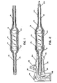
- Figure 1 illustrates an electrical fuse modified in accordance with this invention. It is to be noted that electrical components other than fuses can be similarly modified in accordance with the invention.
- the fuse, 10 has metal end caps, 12, and 14.
- Conductors or studs, 16 and 18, are hollow metal cylinders having cylindrical end portions which provide an interference fit over the metal end caps, 12 and 14, respectively.
- the studs are of spun copper. As discussed above, studs of other metals, which can be spun, deep drawn or sprayed, can be used.
- a corona control layer, 20, is positioned over the body of the fuse and overlaps the metal end caps.
- the corona control layer, 20 is a layer of a semi-conductive stress-grading polymeric material comprising conductive particles dispersed in a polymeric matrix. This layer has been applied by positioning a heat-shrinkable tubing of semi-conductive polymeric material over the fuse and then heating to cause the tubing to shrink into intimate contact with the fuse.
- a layer of electrically insulating material, 22, is positioned over the corona control layer, 20, and the electrical conductive studs, 16 and 18.
- This insulating layer has been applied in the form of a heat-shrinkable tubing, which is placed in position over the fuse and studs and heated, causing it to shrink into contact with the underlying components. As shown in the drawing, end regions of the studs extend beyond the insulating layer for a distance of about 2.54 cms (1 inch).
- An outer conductive shield, 24, is positioned over the insulating layer.
- the shield, 24, does not extend along the entire length of the insulating layer, 22.
- the conductive layer is set back about 12.7 cm (5 inches) from the end of the insulating layer.
- conductive shield, 24, is a layer of semi-conductive polymeric material. This layer has also been applied in the form of heat-shrinkable tubing. When the fuse is installed in a high voltage line, the shield, 24, can be electrically connected to the shields of the elbow connectors or disconnectable joints as illustrated more fully in Figure 2.
- the modified fuse illustrated in Figure 1 is provided with end fittings, 26 and 28, which provide attachment lugs for the separable connector.
- One end of the modified fuse is inserted into a commercially available elbow connector.
- the elbow connector comprises a molded semi-conductive housing, 30, adhered to the outer surface of insulation layer, 32.
- the housing further contains conductive insert, 33.
- the elbow connector is further provided with a grounding eye, 34, a voltage test point, 35, having a protective cap, and a reinforced pulling ring, 36, which enables the connector to be readily moved.
- a modified fuse in accordance with this invention is shown inserted into the cable receiving end of the elbow connector.
- the modified fuse comprises: the fuse, 10, metal end caps, 12 and 14 to which are attached metal studs 16 and 18, a corona control layer 20, an insulating layer 22 and an outer conductive shield, 24.
- the studs in this embodiment, are provided with end fittings, 26 and 28, provided with attachment lugs. Each stud and corresponding end fitting may comprise an integral piece by appropriately forming the end of the stud. End fitting, 26, with a female threaded attachment lug makes an electrical connection via a male threaded copper connecting pin, 38.
- the outer conductive shield, 24, of the fuse makes contact with the conductive shield, 30, of the elbow connector and the conductive stud, 16, of the fuse contacts the semi-conductive insert, 33, of the connector.
- the electrical connection between the studs, 16 and 18, and separable connectors may also be made with suitable "multi-Lam" or similar connectors known to the art.
- the elbow connector is provided with a copper contact pin, 38, which is adapted to provide electrical connection to a circuit component inserted in the other end of the elbow connector.
- FIG. 3 An alternative embodiment is illustrated in Figure 3.
- a fuse modified in accordance with this invention is jointed to a shielded power cable.
- conductive stud, 16 is connected to end cap, 12, of fuse, 10.
- a corona control layer, 20, an insulating layer, 22, and an outer conductive shield, 24, are placed over the fuse and conductors as described above and illustrated in Figure 1.
- Stud, 16, is spliced to cable conductor, 40, by a conventional crimping method indicated as, 41.
- the crimp can be an integral part of the stud, 16, as shown in Figure 3.
- the power cable illustrated in Figure 3 is a 15 kv polyethylene cable comprising a 50 mm 2 copper conductor, 40, polyethylene dielectric, 42, graphite layer, 44, graphite impregnated cloth layer, 46, tape shield, 48, and outer jacket (not shown).
- the central copper conductor, 40 was crimped to the conductor, 16, of the modified fuse.
- Shield, 48 was cut back from the end of the dielectric for a distance ranging from 9 to 15 cm to expose the graphite impregnated cloth layer, 46.
- the cloth layer was cut back to 2 cm from the screen, and the graphite layer extending beyond 1 cm from the cloth layer was removed.
- a quantity of epihalohydrin stress-grading material, 50 as described in British Patent No. 1,604,612, was applied over the crimp and exposed conductors, and a piece of heat-recoverable stress-grading tubing, 52, was recovered overthe splice so that it conformed to the contours of the splice and overlapped the cable shield, 48, at each end.
- the fuse need not be modified in the same manner at each end.
- the modified fuse need not be connected to the power cable or other electrical equipment in the same manner at each end thereof.
- one end of the modified fuse can be connected to a transformer using a standard elbow connector while the other end can be connected to a power cable by a separable joint.
- the elongate electrical conductor need not be unitary, but can comprise interconnected segments.
- the elongate conductor can comprise a first segment adapted to be secured to the end of the fuse, or other electrical component, and a second segment crimped onto the first segment.
- the electrical conductor can have preinstalled layers of electrical insulation and shielding.
- the elongate conductor can comprise, as a first segment, a relatively. short stud having a cylindrical end portion which provides an interference fit over end cap of the fuse as illustrated in Figure 1.
- a length of electrical cable having insulation and shielding already installed can then be connected to the stud by means of a crimp, similar to the crimp in Figure 3 between a power cable and the elongate conductor.
- the length of cable is relatively short, about five feet, and is crimped to the stud of the first segment before the fuse is insulated and shielded.
- the fuse is insulated and shielded as described above. Since the length of cable is pre-insulated and shielded, the insulation and shielding of the fuse does not need to extend fully along the length of cable. The insulation and shielding should extend beyond the crimped end of the cable and overlap the existing insulation and shield of the cable. The shield of the fuse should make electrical contact with the shield of the length of cable to provide a continuity.
- the end of the length of cable remote from the fuse should have the insulation and shielding cut back appropriate distances to enable the cable end to be readily connected in-line with a power cable or other electrical equipment.
Landscapes
- Cable Accessories (AREA)
Abstract
Description
- This invention relates to electrical components adapted to be inserted into high voltage electric circuits, and in particular to high voltage fuses which can be readily connected into a distribution power system.
- Various electrical components are inserted into high voltage power distribution systems, i.e. power systems of above about 1 kilovolt, typically between 5 and 36 kilovolts. Such components include, for example, transformers, rectifiers, fuses, reactors, motors and the like. It is customary in electrical power distribution systems to house electrical components such as fuses, distribution transformers and other apparatus, in a common grounded apparatus box or housing. The various individual components are provided with appropriate insulation and protection as required.
- Fuses used in power distribution systems can be insulated and protected by modules of molded polymeric material. Such modules generally comprise two molded halves into which the fuse is inserted and the molded halves are secured together. The modules can be provided with a corona preventing inner shield and/or an outer ground shield, if desired. Examples of molded fuse modules can be found in U.S. Patents Nos. 3,559,141,3,818,407,3,946,351 and 4,060,785. The molded fuse modules of this type are generally relatively bulky, subject to leakage of moisture at the join between the molded halves, and expensive to manufacture.
- Another approach to providing an enclosure for electrical components such as fuses and the like, is described in U.S. Patent No. 3,085,138. This patent relates to an electric connection assembly adapted for field use. The electric connection assembly can be used to connect a fuse into an electric circuit. The assembly is provided in kit form and includes a pair of socket members each adapted to receive at one end the conductor of a cable and at the other end an electrical instrumentality, e.g. the fuse, and a pair of housing members, which encompass the socket members, electrical instrumentality and cable ends. In use the socket and housing members are installed on the ends of the cables and then the fuse is inserted. The housing members are then joined together where they meet, which is at approximately the mid-point of the fuse. The main disadvantage of this approach is the high possibility of leakage of water at the joint between the two housing members.
- Yet another approach is illustrated in U.S. Patent No. 3,678,432. In this approach the insulated body of the fuse is enclosed in a conductive shielding module, and the fuse ends or terminals are inserted into first and second conductor termination modules. The termination modules have frusto-conical end surfaces that form water tight voltage grading seals with the corresponding frusto-conical end surfaces of the fuse module. The termination modules must be specially produced for use with the fuse module and are not suitable for use with other standard electrical components.
- This invention provides a modified fuse or other electrical component which is insulated and shielded without requiring a bulky housing or module. Further, the ends of the fuse are modified so that they can be directly terminated to electrical equipment or jointed to high voltage power cables using conventional techniques. For example, the modified component can be used with typical separable insulated connectors such as high voltage elbow connectors and of separable high voltage joints. Alternatively, the ends of the modified component can be directly jointed to the ends of shielded power cables by conventional jointing methods.
- The invention provides a shielded electrical component which comprises:
- (a) an electrical component having at each end thereof a terminal for electrically connecting the component into an electric circuit;
- (b) an electrical conductor connected to one of the end terminals;
- (c) a second electrical conductor connected to the other of the terminals;
- (d) an electrically insulating layer positioned over the electrical component and said conductors; and
- (e) an outer conductive layer positioned over said insulating layer;
- characterised in that the electrical conductors are elongate, and in that the electrically insulating layer is positioned such that an end region of each of said conductors remains free of insulation, said electrical component thereby being converted at each end thereof to the electrical and mechanical equivalent of the end of a shielded high voltage power cable having the end region of its conductor free of insulation.
- A method of producing said shielded component is also provided.
-
- Figure 1 illustrates a fuse modified in accordance with this invention.
- Figure 2 illustrates the modified fuse inserted in a commercially available insulated elbow connector.
- Figure 3 illustrates the modified fuse crimped directly onto the end of a power cable.
- As mentioned above, various electrical components are inserted into high voltage power distribution systems, i.e. power systems of above about 1 kilovolt, typically between 5 and 36 kilovolts. Such components include, for example, transformers, rectifiers, fuses, reactors, motors and the like. This invention concerns modification of such components. For the sake of convenience, the discussion of this invention is directed to current limiting fuses which are modified to be inserted into a power system. It is to be understood, that this invention is not limited to fuses but also covers other electrical components. The fuse, or other electrical component, is provided in accordance with this invention with first and second conductors each of which is electrically connected to one of the terminals of the component. In the case of a fuse the terminals are typically conductive end caps on the fuse housing. Such conductors can comprise metal studs which are cylindrical or tubular in configuration and are referred to as conductors, studs or conductive studs in the following discussion of the invention. The stud can be of, for example, copper, tinned copper, aluminum or other metal. The stud can be attached to the metal end cap by any conventional means such as soldering or welding. Alternatively, the stud can be an integral part of the end caps of the fuse or an extension of the end terminals of other electrical components. As described in more detail below, in a preferred embodiment the stud is provided with cylindrical end portions which slide over the end caps of the fuse to provide an interference fit. The length of the stud or conductor depends on the design of the connector member to be used with the fuse to connect it to the power system.
- An insulating layer is positioned over the fuse and a portion of the conductive studs such that end regions of the conductors remain uninsulated. The length of the uninsulated end regions of the studs depends on the method to be used in connecting the conductive studs to the power line or cable, as described more fully below.
- This insulation layer can be resilient or non- resilient and preferably comprises a layer of polymeric material. The polymeric material should have a dielectric strength of at least 78.7 kilovolts per cm (200 volts/mil), preferably at least 118 kilovolts per cm (300 volts/mil).
- The polymeric material can be a thermoplastic, elastomer or thermoset, for example, polyethylene, ethylene-propylene copolymer or ethylenepropylene-diene terpolymers, polyacrylates, silicone polymers and epoxy resins. The polymer can contain the usual additives, such as stabilizers, antioxidants, anti-tracking agents and the like. Typical compositions for use as high voltage insulating material are described in U.S. Patents Nos. 4,001,128 to Penneck, 4,100,089 to Commack, 4,189,392 to Penneck and 4,219,607 to Commack et al, and U.K. Patents Nos. 1,337,951 and 1,337,952 both to Penneck.
- The thickness of the insulation layer depends on the voltage class and type of fuse (or other component) and dielectric properties of the particular polymer composition used. The thickness of the insulation is generally in the range of about 0.2 cm to about 3.5 cm, preferably in the range of about 0.25 cm to about 1 cm.
- The insulation layer can be applied by any conventional technique. For example, the insulating layer can be molded and positioned over the fuse and studs. Another method of applying the insulation layer is to place a dimensionally-recoverable, in particular a heat-shrinkable, tubular article of polymeric material over the fuse and conductive studs and then applying heat to cause the tube to shrink into intimate contact therewith. Heat-shrinkable polymeric tubular articles and methods for their manufacture are known, see for example, U.S. Patent No. 3,086,242 to Cook. Dimensionally-recoverable articles which recover without application of heat can also be used. Such dimensionally-recoverable articles are known, see for example, U.S. Patent No. 4,135,553 to Evans et al.
- As is conventional with high voltage insulation, there should be no voids between the insulation and the underlying conductor and/or component. Since the surfaces of the fuse, studs and insulation layer are not perfectly smooth, the inner surface of the polymer layer can be coated with a conductive material, where required. The conductive coating on the inner surface of the insulation prevents localized electrical stress between the insulation and the underlying conductive stud and/or component across any void which might be present.
- An outer conductive layer is positioned over the insulating layer. The conductive outer layer preferably has a resistivity of less than about 5000 ohm-cm, and most preferably less than about 100 ohm-cm. Typically the conductive outer layer has a resistivity in the range of from about 10 to about 1000 ohm-cm.
- The conductive outer layer can comprise a metal layer or a layer of polymeric matrix having a conductive filler dispersed therein. The polymeric matrix may comprise any of the polymeric materials listed above, and the conductive filler may comprise metal particles or a conductive carbon black. An example of such a composition can be found in British Patent No. 1,294,665 to Heaven. Conductive polymeric compositions which can be used in accordance with this invention generally comprise from about 10 to about 70, preferably from about 10 to about 20, and most preferably from about 15 to about 17, parts by weight of conductive filler, based on a total weight of 100 parts of polymeric matrix plus filler.
- The outer conductive layer can be applied over the insulating layer in any convenient manner. The conductive layer can be, for example, applied as a deposited layer of metal, a layer of conductive paint, a layer comprising a conductive polymeric article or the like. For example, the layer can be applied as a molded tubular article of conductive polymeric material or a dimensionally-recoverable tubular article. Preferably, it is a heat-shrinkable tubular article. The tubular article is placed over the insulating layer and heated to cause it to shrink into contact with the insulating layer.
- The insulating and outer conductive layers can be applied separately or can be formed into a unitary structure before being placed over the fuse. For example, the two layers can be molded together to form a molded tubular article shaped to accommodate the fuse and conductive studs. If the layers are to be applied as dimensionally-recoverable tubular articles, such as, heat-shrinkable articles, a composite article of the two layers can be formed, for example, by coextrusion, by coating a conductive layer of metal or paint on the surface of the article or any other convenient technique. The composite article is then positioned over the fuse and conductors and heated to cause it to shrink into contact with the fuse and studs.
- The outer conductive layer is generally set back from the ends of the insulating layer. The amount of set back depends on the manner in which the modified fuse is to be connected into a power system. As discussed more fully below, the fuse can be used in conjunction with typical commercially available insulated separable connectors, or can be spliced directly to power cables or other electrical equipment. The amount of set back of the insulation layer on the fuse is determined by the method by which it is to be inserted into the electrical network.
- The modified fuse can be provided with an outer protective jacket. This outer jacket is preferably of a polymeric material, such as polymeric materials conventionally used as the outer jacket of power cables. For example, the outer jacket can be of polyethylene, polyvinyl chloride, or the like. Various additives such as stabilizers, flame retardants and the like can be incorporated into the polymeric material. The protective jacket provides mechanical and environmental protection for the conductive and insulation layers.
- In the event that the electrical component is such that corona discharge must be suppressed, as is the case with certain current limiting fuses, a corona control layer may be positioned immediately over the tubular housing of the fuse between the fuse housing and the insulation layer.
- The corona control layer can comprise a discontinuous conductive layer (i.e. a discontinuous Faraday cage) extending over the fuse body between the metal end caps. The discontinuity in the conductive layer provides an insulation filled gap which prevents current flow along the conductive layer in the event the fuse opens to limit current flow through the circuit. The conductive layer can be, for example, a layer of conductive paint sprayed or otherwise coated on the inner surface of the insulation layer. The corona control layer can also be a semiconductive polymeric stress-grading layer which can be continuous or discontinuous.
- If the stress-grading layer extends between the end caps of the fuse, the impedence of the stress-grading layer should be at least about 107 ohms. If the stress-grading layer is discontinuous, with insulation filling the gap, the stress-grading material and the length of the segments of the stress-grading material should be selected such that when the fuse has opened the electrical field across the gap should be less than about 10,000 volts per centimeter.
- Examples of stress-grading materials suitable for use in the invention include: an electrically insulating polymeric material that contains carbon black; a material comprising iron oxide; a material comprising zinc oxide; a material comprising silicon carbide; a polymeric material disclosed in UK Patent Specification Nos. 1470504 or 1470501. Stress-grading materials typically have a specific impedance in the range from about 106 ohm-cm to about 1010 ohm-cm, preferably from about 5x10⁷ ohm-cm to about 5x10⁹ ohm-cm and most preferably from about 108 ohm-cm to 109 ohm-cm.
- The stress-grading material can be in the form of a molded or a dimensionally-recoverable, for example a heat-shrinkable, tubular article, for example, as described in the above-mentioned U.S. Patent No. 3,950,604. The stress-grading semi-conductive layer can then be applied, for example, by positioning a heat-shrinkable tubular article over the fuse and heating to cause the tubular article to shrink into intimate contact with the fuse. The stress-grading layer and insulation layer can each be heat-shrinkable and can be laminated together or coextruded to form an integral heat-shrinkable article. A suitable heat shrinkable article of this type is available from the Raychem Corporation, Menlo Park, California, under its trademark SCTM.
- Stress-grading material in the form of a paint can be applied to the interior surface of the insulation layer or to the exterior surface of the fuse, by coating it, e.g: by spraying or brushing. Stress-grading material in the form of a paint can comprise, for example, a mixture of graphite and silicon carbide particles in a liquid curable resin system such as an epoxy resin.
- By modifying the fuse in the manner described, the ends of the fuse are converted into the electrical and mechanical equivalent of the ends of a shielded power cable. This modification of the ends allows either end of the fuse (or other electrical component) to be terminated in or connected to a shielded or non-shielded manner analogous to the techniques typically used for power cables designed for similar operating voltages.
- The modified fuse of this invention can thus be adapted for insertion into insulated separable connectors such as high voltage elbow connectors or separable high voltage joints. The length of the exposed ends of the conductive studs, the length of the insulation layer and the outer shield all depend on the exact particular separable connector to be used with the modified fuse. The modified fuse can be inserted into the end of such a connector generally used for receiving the end of a high voltage power cable. A layer of grease is provided over the exposed insulation layer of the fuse before it is inserted in the connector. The grease aids insertion of the fuse and fills any voids between the insulation layer and the connector thereby preventing electrical discharge between the end of the fuse conductor and conductive shield of the connector or fuse. The other end of the separable connector can be connected to an appropriate component of a high voltage distribution system such as a circuit breaker, transformer, a power cable, and the like. Also, since the ends of the fuse are modified in accordance with this invention to be electrically and mechanically equivalent to the ends of a shielded power cable, the fuse can be connected directly to another power cable by means of conventional jointing techniques, such as crimping, etc.
- The invention is illustrated in more detail by the embodiments depicted in the accompanying drawings. In the drawing, Figure 1 illustrates an electrical fuse modified in accordance with this invention. It is to be noted that electrical components other than fuses can be similarly modified in accordance with the invention. In Figure 1, the fuse, 10, has metal end caps, 12, and 14. Conductors or studs, 16 and 18, are hollow metal cylinders having cylindrical end portions which provide an interference fit over the metal end caps, 12 and 14, respectively. In the illustrated embodiment the studs are of spun copper. As discussed above, studs of other metals, which can be spun, deep drawn or sprayed, can be used. A corona control layer, 20, is positioned over the body of the fuse and overlaps the metal end caps. In the illustrated embodiment the corona control layer, 20, is a layer of a semi-conductive stress-grading polymeric material comprising conductive particles dispersed in a polymeric matrix. This layer has been applied by positioning a heat-shrinkable tubing of semi-conductive polymeric material over the fuse and then heating to cause the tubing to shrink into intimate contact with the fuse.
- A layer of electrically insulating material, 22, is positioned over the corona control layer, 20, and the electrical conductive studs, 16 and 18. This insulating layer has been applied in the form of a heat-shrinkable tubing, which is placed in position over the fuse and studs and heated, causing it to shrink into contact with the underlying components. As shown in the drawing, end regions of the studs extend beyond the insulating layer for a distance of about 2.54 cms (1 inch).
- An outer conductive shield, 24, is positioned over the insulating layer. The shield, 24, does not extend along the entire length of the insulating layer, 22. In the illustrated embodiment, the conductive layer is set back about 12.7 cm (5 inches) from the end of the insulating layer. In the illustrated embodiment, conductive shield, 24, is a layer of semi-conductive polymeric material. This layer has also been applied in the form of heat-shrinkable tubing. When the fuse is installed in a high voltage line, the shield, 24, can be electrically connected to the shields of the elbow connectors or disconnectable joints as illustrated more fully in Figure 2.
- In Figure 2, the modified fuse illustrated in Figure 1 is provided with end fittings, 26 and 28, which provide attachment lugs for the separable connector. One end of the modified fuse is inserted into a commercially available elbow connector. The elbow connector comprises a molded semi-conductive housing, 30, adhered to the outer surface of insulation layer, 32. The housing further contains conductive insert, 33. The elbow connector is further provided with a grounding eye, 34, a voltage test point, 35, having a protective cap, and a reinforced pulling ring, 36, which enables the connector to be readily moved.
- A modified fuse in accordance with this invention is shown inserted into the cable receiving end of the elbow connector. As discussed above, the modified fuse comprises: the fuse, 10, metal end caps, 12 and 14 to which are attached
metal studs corona control layer 20, an insulatinglayer 22 and an outer conductive shield, 24. As mentioned above, the studs, in this embodiment, are provided with end fittings, 26 and 28, provided with attachment lugs. Each stud and corresponding end fitting may comprise an integral piece by appropriately forming the end of the stud. End fitting, 26, with a female threaded attachment lug makes an electrical connection via a male threaded copper connecting pin, 38. It is to be noted that when the modified fuse is inserted into the elbow connector, the outer conductive shield, 24, of the fuse makes contact with the conductive shield, 30, of the elbow connector and the conductive stud, 16, of the fuse contacts the semi-conductive insert, 33, of the connector. The electrical connection between the studs, 16 and 18, and separable connectors may also be made with suitable "multi-Lam" or similar connectors known to the art. The elbow connector is provided with a copper contact pin, 38, which is adapted to provide electrical connection to a circuit component inserted in the other end of the elbow connector. - An alternative embodiment is illustrated in Figure 3. In Figure 3, a fuse modified in accordance with this invention is jointed to a shielded power cable. For the sake of convenience, only one end of the fuse is illustrated. It is to be understood that the other end of the modified fuse can be similarly joined to a shielded power cable or joined to such a cable by other convenient techniques. In Figure 3, conductive stud, 16, is connected to end cap, 12, of fuse, 10. A corona control layer, 20, an insulating layer, 22, and an outer conductive shield, 24, are placed over the fuse and conductors as described above and illustrated in Figure 1. Stud, 16, is spliced to cable conductor, 40, by a conventional crimping method indicated as, 41. The crimp can be an integral part of the stud, 16, as shown in Figure 3.
- The power cable illustrated in Figure 3 is a 15 kv polyethylene cable comprising a 50 mm2 copper conductor, 40, polyethylene dielectric, 42, graphite layer, 44, graphite impregnated cloth layer, 46, tape shield, 48, and outer jacket (not shown). The central copper conductor, 40, was crimped to the conductor, 16, of the modified fuse.
- Shield, 48, was cut back from the end of the dielectric for a distance ranging from 9 to 15 cm to expose the graphite impregnated cloth layer, 46. The cloth layer was cut back to 2 cm from the screen, and the graphite layer extending beyond 1 cm from the cloth layer was removed. A quantity of epihalohydrin stress-grading material, 50, as described in British Patent No. 1,604,612, was applied over the crimp and exposed conductors, and a piece of heat-recoverable stress-grading tubing, 52, was recovered overthe splice so that it conformed to the contours of the splice and overlapped the cable shield, 48, at each end. A piece of high voltage insulating heat-recoverable tubing, 54, of recovered wall thickness 4 mm, having a volume resistivity of at least 10 ohm-cm and a length equal to that of the stress-grading tubing, was then recovered over the stress-grading layer, 52, followed by an outer conductive polymer layer, 56, of wall thickness about 0.7 mm.
- Numerous other variations and embodiments are possible, as will be readily apparent to one skilled in the art. The fuse need not be modified in the same manner at each end. Also the modified fuse need not be connected to the power cable or other electrical equipment in the same manner at each end thereof. For example, one end of the modified fuse can be connected to a transformer using a standard elbow connector while the other end can be connected to a power cable by a separable joint.
- The elongate electrical conductor need not be unitary, but can comprise interconnected segments. For example, the elongate conductor can comprise a first segment adapted to be secured to the end of the fuse, or other electrical component, and a second segment crimped onto the first segment. The electrical conductor can have preinstalled layers of electrical insulation and shielding. For example, the elongate conductor can comprise, as a first segment, a relatively. short stud having a cylindrical end portion which provides an interference fit over end cap of the fuse as illustrated in Figure 1. As the second segment, a length of electrical cable having insulation and shielding already installed can then be connected to the stud by means of a crimp, similar to the crimp in Figure 3 between a power cable and the elongate conductor. In this embodiment the length of cable is relatively short, about five feet, and is crimped to the stud of the first segment before the fuse is insulated and shielded. After the length of cable has been crimped to the stud, the fuse is insulated and shielded as described above. Since the length of cable is pre-insulated and shielded, the insulation and shielding of the fuse does not need to extend fully along the length of cable. The insulation and shielding should extend beyond the crimped end of the cable and overlap the existing insulation and shield of the cable. The shield of the fuse should make electrical contact with the shield of the length of cable to provide a continuity. The end of the length of cable remote from the fuse should have the insulation and shielding cut back appropriate distances to enable the cable end to be readily connected in-line with a power cable or other electrical equipment.
- The present invention has been described in considerable detail with reference to certain preferred embodiments thereof. However, other embodiments are possible. For example, electrical components other than fuses can be modified in accordance with this invention and connected into any electric circuit by appropriate means.
Claims (22)
characterised in that the electrical conductors (16, 18) are elongate, and in that the electrically insulating layer (22) is positioned such that an end region of each of said conductors remains free of insulation, said electrical component (10) thereby being converted at each end thereof to the electrical and mechanical equivalent of the end of a shielded high voltage power cable having the end region of its conductor free of insulation.
Priority Applications (1)
| Application Number | Priority Date | Filing Date | Title |
|---|---|---|---|
| AT83902221T ATE43751T1 (en) | 1982-06-14 | 1983-06-14 | SHIELDED ELECTRICAL COMPONENTS. |
Applications Claiming Priority (4)
| Application Number | Priority Date | Filing Date | Title |
|---|---|---|---|
| US38831082A | 1982-06-14 | 1982-06-14 | |
| US388310 | 1982-06-14 | ||
| US40050982A | 1982-07-21 | 1982-07-21 | |
| US400509 | 1982-07-21 |
Publications (3)
| Publication Number | Publication Date |
|---|---|
| EP0111553A1 EP0111553A1 (en) | 1984-06-27 |
| EP0111553A4 EP0111553A4 (en) | 1986-10-02 |
| EP0111553B1 true EP0111553B1 (en) | 1989-05-31 |
Family
ID=27012257
Family Applications (1)
| Application Number | Title | Priority Date | Filing Date |
|---|---|---|---|
| EP19830902221 Expired EP0111553B1 (en) | 1982-06-14 | 1983-06-14 | Shielded electric components |
Country Status (5)
| Country | Link |
|---|---|
| EP (1) | EP0111553B1 (en) |
| CA (1) | CA1216015A (en) |
| DE (1) | DE3380000D1 (en) |
| GB (1) | GB2125637B (en) |
| WO (1) | WO1984000078A1 (en) |
Cited By (3)
| Publication number | Priority date | Publication date | Assignee | Title |
|---|---|---|---|---|
| DE4444151A1 (en) * | 1994-12-12 | 1996-06-13 | Hagen Batterie Ag | Storage battery cells arrangement |
| CN104221220A (en) * | 2012-03-27 | 2014-12-17 | 保险丝公司 | Fuse end cap with crimpable terminal |
| US10998651B2 (en) | 2019-05-22 | 2021-05-04 | Nvent Services Gmbh | Flame-resistant heat shrink assemblies for trace heating cables |
Families Citing this family (14)
| Publication number | Priority date | Publication date | Assignee | Title |
|---|---|---|---|---|
| FR2681734B1 (en) * | 1991-09-25 | 1993-12-10 | Sodern Etudes Realisa Nucleaires | CONNECTION DEVICE BETWEEN A HIGH VOLTAGE CABLE AND A HIGH VOLTAGE OPERATION SYSTEM INCLUDING AN ELECTRONIC PROXIMITY CIRCUIT. |
| US5591366A (en) * | 1994-06-23 | 1997-01-07 | Husky Injection Molding Systems Ltd. | Injection molding heater including circuit breaking means |
| DE19640106A1 (en) * | 1996-09-28 | 1998-04-02 | Efen Elektrotech Fab | Under-oil fuse |
| SE516289C2 (en) * | 1999-05-27 | 2001-12-10 | Abb Ab | Switchgear |
| DE10049435A1 (en) * | 2000-10-06 | 2002-04-18 | Giesecke & Devrient Gmbh | Procedure for processing sheet material |
| US7794254B2 (en) | 2007-04-30 | 2010-09-14 | Tronic Limited | Submersible electrical connector |
| GB0708362D0 (en) | 2007-04-30 | 2007-06-06 | Tronic Ltd | Connector |
| US7959454B2 (en) | 2009-07-23 | 2011-06-14 | Teledyne Odi, Inc. | Wet mate connector |
| US8968018B2 (en) | 2009-08-05 | 2015-03-03 | Teledyne Instruments, Inc. | Electrical penetrator assembly |
| EP2462312B1 (en) * | 2009-08-05 | 2022-08-17 | Teledyne Instruments, Inc. | Electrical penetrator assembly |
| FR2983361B1 (en) * | 2011-11-28 | 2013-12-27 | Michel Bechet | REMOVABLE ELECTRICAL PROTECTION DEVICE FOR SINGLE USE AND ITS USE IN A SOLAR POWER ELECTRICAL PHOTOVOLTAIC PRODUCTION PLANT |
| US10992254B2 (en) | 2014-09-09 | 2021-04-27 | Shoals Technologies Group, Llc | Lead assembly for connecting solar panel arrays to inverter |
| CN110911182A (en) * | 2019-12-28 | 2020-03-24 | 天水长城开关厂有限公司 | Large-current isolation contact support for environment-friendly gas-filled cabinet |
| DE102021107539A1 (en) * | 2021-03-25 | 2022-09-29 | Bayerische Motoren Werke Aktiengesellschaft | Protective device for a high-voltage cable, high-voltage cable, high-voltage vehicle electrical system and motor vehicle |
Family Cites Families (7)
| Publication number | Priority date | Publication date | Assignee | Title |
|---|---|---|---|---|
| US3388351A (en) * | 1964-02-14 | 1968-06-11 | Westinghouse Electric Corp | Foil or strip inductor device |
| US3686604A (en) * | 1969-08-12 | 1972-08-22 | Rte Corp | Current interrupting safe break terminator |
| US3781745A (en) * | 1969-09-10 | 1973-12-25 | Joslyn Mfg & Supply Co | Fused coupler assembly |
| US3559141A (en) * | 1969-10-23 | 1971-01-26 | Gen Electric | Underground electric power cable fuse housing having a semi-conductive corona shield |
| DE2010143A1 (en) * | 1970-03-04 | 1971-09-23 | Mueller C H F Gmbh | High voltage cables for X-ray tubes |
| US3678432A (en) * | 1971-04-26 | 1972-07-18 | Gen Electric | Vented fuse module for underground power cable system |
| US3818407A (en) * | 1972-09-25 | 1974-06-18 | Amerace Esna Corp | High voltage fuse enclosure |
-
1983
- 1983-06-14 DE DE8383902221T patent/DE3380000D1/en not_active Expired
- 1983-06-14 GB GB08316210A patent/GB2125637B/en not_active Expired
- 1983-06-14 CA CA000430354A patent/CA1216015A/en not_active Expired
- 1983-06-14 WO PCT/US1983/000926 patent/WO1984000078A1/en not_active Ceased
- 1983-06-14 EP EP19830902221 patent/EP0111553B1/en not_active Expired
Cited By (3)
| Publication number | Priority date | Publication date | Assignee | Title |
|---|---|---|---|---|
| DE4444151A1 (en) * | 1994-12-12 | 1996-06-13 | Hagen Batterie Ag | Storage battery cells arrangement |
| CN104221220A (en) * | 2012-03-27 | 2014-12-17 | 保险丝公司 | Fuse end cap with crimpable terminal |
| US10998651B2 (en) | 2019-05-22 | 2021-05-04 | Nvent Services Gmbh | Flame-resistant heat shrink assemblies for trace heating cables |
Also Published As
| Publication number | Publication date |
|---|---|
| GB8316210D0 (en) | 1983-07-20 |
| WO1984000078A1 (en) | 1984-01-05 |
| EP0111553A4 (en) | 1986-10-02 |
| EP0111553A1 (en) | 1984-06-27 |
| CA1216015A (en) | 1986-12-30 |
| DE3380000D1 (en) | 1989-07-06 |
| GB2125637B (en) | 1986-12-31 |
| GB2125637A (en) | 1984-03-07 |
Similar Documents
| Publication | Publication Date | Title |
|---|---|---|
| CA1216015A (en) | Shielded electric components | |
| US4589939A (en) | Insulating multiple-conductor cables using coated insert means | |
| US3307137A (en) | Conductor termination | |
| EP0225190B2 (en) | Cable connection | |
| CA1152588A (en) | Enclosure for cable termination or joint | |
| US4390745A (en) | Enclosures for electrical apparatus, cable and enclosure combinations, and kits and methods for their construction | |
| CA1078939A (en) | Electrical connector with adaptor for paper-insulated lead jacketed electrical cables and method | |
| US4485269A (en) | Cable sealing | |
| US4551915A (en) | Method for terminating a high voltage cable | |
| IL111241A (en) | Closure for high voltage cable connections | |
| CA1244900A (en) | Cable joints and terminations | |
| GB2042818A (en) | Enclosed for electrical apparatus | |
| EP0153174A2 (en) | Insulating multiple conductor cables | |
| EP0075471B1 (en) | Electrical bushing and method of manufacture thereof | |
| GB2288696A (en) | Cable splice or termination | |
| GB2097203A (en) | Cable sealing | |
| US12431700B2 (en) | Cold-shrinkable protective housing and methods including same | |
| CA1197580A (en) | Water-proofing joint assembly for power cables | |
| JPS59501335A (en) | shield electrical equipment | |
| JPS6176005A (en) | Method of connecting cable | |
| GB2111769A (en) | Enclosure for cable termination or joint | |
| JPH084633Y2 (en) | Termination of lead cable for DC withstanding voltage test | |
| Medek | 13 Splicing, Terminating | |
| Medek | SPLICING, TERMINATING, AND ACCESSORIES | |
| Balaska et al. | SPLICING, TERMINATING, AND ACCESSORIES |
Legal Events
| Date | Code | Title | Description |
|---|---|---|---|
| PUAI | Public reference made under article 153(3) epc to a published international application that has entered the european phase |
Free format text: ORIGINAL CODE: 0009012 |
|
| 17P | Request for examination filed |
Effective date: 19840215 |
|
| AK | Designated contracting states |
Designated state(s): AT BE CH DE FR LI NL SE |
|
| A4 | Supplementary search report drawn up and despatched |
Effective date: 19861002 |
|
| 17Q | First examination report despatched |
Effective date: 19871126 |
|
| RAP1 | Party data changed (applicant data changed or rights of an application transferred) |
Owner name: RAYCHEM CORPORATION (A DELAWARE CORPORATION) |
|
| GRAA | (expected) grant |
Free format text: ORIGINAL CODE: 0009210 |
|
| AK | Designated contracting states |
Kind code of ref document: B1 Designated state(s): AT BE CH DE FR LI NL SE |
|
| PG25 | Lapsed in a contracting state [announced via postgrant information from national office to epo] |
Ref country code: SE Effective date: 19890531 Ref country code: NL Effective date: 19890531 Ref country code: LI Effective date: 19890531 Ref country code: CH Effective date: 19890531 Ref country code: BE Effective date: 19890531 Ref country code: AT Effective date: 19890531 |
|
| REF | Corresponds to: |
Ref document number: 43751 Country of ref document: AT Date of ref document: 19890615 Kind code of ref document: T |
|
| REF | Corresponds to: |
Ref document number: 3380000 Country of ref document: DE Date of ref document: 19890706 |
|
| ET | Fr: translation filed | ||
| REG | Reference to a national code |
Ref country code: CH Ref legal event code: PL |
|
| NLV1 | Nl: lapsed or annulled due to failure to fulfill the requirements of art. 29p and 29m of the patents act | ||
| PLBE | No opposition filed within time limit |
Free format text: ORIGINAL CODE: 0009261 |
|
| STAA | Information on the status of an ep patent application or granted ep patent |
Free format text: STATUS: NO OPPOSITION FILED WITHIN TIME LIMIT |
|
| 26N | No opposition filed | ||
| PGFP | Annual fee paid to national office [announced via postgrant information from national office to epo] |
Ref country code: FR Payment date: 19980609 Year of fee payment: 16 |
|
| PGFP | Annual fee paid to national office [announced via postgrant information from national office to epo] |
Ref country code: DE Payment date: 19980622 Year of fee payment: 16 |
|
| PG25 | Lapsed in a contracting state [announced via postgrant information from national office to epo] |
Ref country code: FR Free format text: THE PATENT HAS BEEN ANNULLED BY A DECISION OF A NATIONAL AUTHORITY Effective date: 19990630 |
|
| PG25 | Lapsed in a contracting state [announced via postgrant information from national office to epo] |
Ref country code: DE Free format text: LAPSE BECAUSE OF NON-PAYMENT OF DUE FEES Effective date: 20000503 |
|
| REG | Reference to a national code |
Ref country code: FR Ref legal event code: ST |