EP0111426A2 - A light for a vehicle visor - Google Patents
A light for a vehicle visor Download PDFInfo
- Publication number
- EP0111426A2 EP0111426A2 EP83307569A EP83307569A EP0111426A2 EP 0111426 A2 EP0111426 A2 EP 0111426A2 EP 83307569 A EP83307569 A EP 83307569A EP 83307569 A EP83307569 A EP 83307569A EP 0111426 A2 EP0111426 A2 EP 0111426A2
- Authority
- EP
- European Patent Office
- Prior art keywords
- light
- housing
- visor
- assembly
- visor body
- Prior art date
- Legal status (The legal status is an assumption and is not a legal conclusion. Google has not performed a legal analysis and makes no representation as to the accuracy of the status listed.)
- Granted
Links
Images
Classifications
-
- B—PERFORMING OPERATIONS; TRANSPORTING
- B60—VEHICLES IN GENERAL
- B60J—WINDOWS, WINDSCREENS, NON-FIXED ROOFS, DOORS, OR SIMILAR DEVICES FOR VEHICLES; REMOVABLE EXTERNAL PROTECTIVE COVERINGS SPECIALLY ADAPTED FOR VEHICLES
- B60J3/00—Antiglare equipment associated with windows or windscreens; Sun visors for vehicles
- B60J3/02—Antiglare equipment associated with windows or windscreens; Sun visors for vehicles adjustable in position
- B60J3/0204—Sun visors
- B60J3/0278—Sun visors structure of the body
- B60J3/0282—Sun visors structure of the body specially adapted for a courtesy mirror
-
- B—PERFORMING OPERATIONS; TRANSPORTING
- B60—VEHICLES IN GENERAL
- B60Q—ARRANGEMENT OF SIGNALLING OR LIGHTING DEVICES, THE MOUNTING OR SUPPORTING THEREOF OR CIRCUITS THEREFOR, FOR VEHICLES IN GENERAL
- B60Q3/00—Arrangement of lighting devices for vehicle interiors; Lighting devices specially adapted for vehicle interiors
- B60Q3/20—Arrangement of lighting devices for vehicle interiors; Lighting devices specially adapted for vehicle interiors for lighting specific fittings of passenger or driving compartments; mounted on specific fittings of passenger or driving compartments
- B60Q3/252—Sun visors
-
- B—PERFORMING OPERATIONS; TRANSPORTING
- B60—VEHICLES IN GENERAL
- B60Q—ARRANGEMENT OF SIGNALLING OR LIGHTING DEVICES, THE MOUNTING OR SUPPORTING THEREOF OR CIRCUITS THEREFOR, FOR VEHICLES IN GENERAL
- B60Q3/00—Arrangement of lighting devices for vehicle interiors; Lighting devices specially adapted for vehicle interiors
- B60Q3/50—Mounting arrangements
- B60Q3/57—Retractable or concealable lighting devices
-
- B—PERFORMING OPERATIONS; TRANSPORTING
- B60—VEHICLES IN GENERAL
- B60Q—ARRANGEMENT OF SIGNALLING OR LIGHTING DEVICES, THE MOUNTING OR SUPPORTING THEREOF OR CIRCUITS THEREFOR, FOR VEHICLES IN GENERAL
- B60Q3/00—Arrangement of lighting devices for vehicle interiors; Lighting devices specially adapted for vehicle interiors
- B60Q3/70—Arrangement of lighting devices for vehicle interiors; Lighting devices specially adapted for vehicle interiors characterised by the purpose
- B60Q3/76—Arrangement of lighting devices for vehicle interiors; Lighting devices specially adapted for vehicle interiors characterised by the purpose for spotlighting, e.g. reading lamps
Definitions
- the present invention relates to a light for a vehicle visor and also to a vehicle visor comprising such a light.
- Visors with illuminated vanity mirrors have become very popular standard and optional items for vehicles.
- the lights provided on such visors can be employed either in connection with a makeup mirror for personal care or when the visor is oriented in a lowered and forwardly extending direction, as lighting for use in reading maps or other material in low ambient light conditions.
- One such visor construction is described in US-A-4,075,468.
- a light for a vehicle visor comprises a light assembly characterised by means for pivotally mounting the light assembly to a visor body for movement about a first axis between a stored position within a recess in the visor to a use position pivoted outwardly from the visor body.
- the recess extends through the visor body to permit the light assembly to be pivoted outwardly to either side of the visor body.
- the light assembly comprises a light housing and the coupling comprises a pivot connection between the light assembly and the means for pivotally mounting the light assembly to the visor body.
- the light assembly comprises a light housing having a lens mounted in one end and a lamp positioned within the housing for directing illumination through the lens.
- the light housing may be relatively flat and has a curved end remote from the one end and sidewalls terminating in spaced relationship at the remote end to define end stops.
- the coupling may include a relatively flat housing having curved slots extending therein and terminating in end walls which engage the end stops of the light housing.
- the pivot connection comprises a pivot pin mounted within the light housing and a pin receiving collar mounted to the housing and concentric with the curved slots.
- the light may include a pivot shaft extending from the housing in a direction generally orthogonal to the axis of the collar and near an end remote from the light housing.
- a visor 10 which has a body 11 which can be made of a moulded polymeric material of the type described in U S-A-3,926,470.
- the visor body 11 includes a central rectangular recess for receiving a mirror and frame assembly 12 including a mirror 13 and frame 14 surrounding the mirror and conventionally mounted within the visor body 11 on a side facing the vehicle occupant when the visor is in a lowered position, as shown in Figure 1.
- the visor assembly also includes a pivot arm 16 mounted to an elbow mounting assembly 18 which can be of conventional construction to permit visor movement.
- the visor 10 can be upholstered in a fabric 15 to match the vehicle interior and includes a rectangular recess 20 extending through the visor body and incorporating a light.
- the recess 20 is a generally vertically extending, elongated, rectangular aperture surrounded by a moulded polymeric frame 22 having a forward facing flange 23 and a rearward facing flange 24 defining a frame into which a pivoted light 30 which can be directed into a number of positions is mounted.
- the lighting includes a light housing assembly 25 which is pivotally coupled to a mounting bracket assembly 50.
- the light housing assembly 25 pivots laterally (i.e. from side-to-side) with respect to the vehicle interior, as illustrated by arrow A in Figure 1, while the mounting bracket is pivotally coupled within the recess 20 to swing the entire light 30 from back to front through the recess 20 to either side of the visor, as illustrated by arrow B in Figure 1.
- the light housing assembly 25 includes an upper housing shell 31 and a lower housing shell 32 each of which are of substantially identical construction and include a U-shaped facing slot 33 and 34 near one end, respectively, for captively receiving and holding a peripheral flange 27 of a light reflector 42.
- the reflector 42 is generally concave with a reflective interior coating to direct light from a lamp 43 outwardly through a lens 35.
- the lens 35 extends along the width of the rectangular first end of the light housing assembly 25 and includes rearwardly projecting locking tabs 36 extending over the ridges defining the recesses 33 and 34. Clearance for the tabs 36 is provided by slots 28 formed in the peripheral flange 27 of the reflector 42.
- the opposite end of each housing half 31 and 32 is curved with a semicircular end 37 and 38, respectively. Mating sidewalls 26 and 29 join and enclose the housing halves when assembled.
- a light assembly 40 is mounted within the housing shells 31 and 32 and includes the light reflector 42, into which a socket 44 is mounted for receiving the lamp 43 mounted within the reflector and into the socket 44.
- the socket 44 is electrically coupled to the vehicle's electrical system by means of conductors 41 and 45, as described below.
- the mating sidewalls 26 and 29 of the shells 31 and 32 have curved rearward edges each terminating in an open, arcuate slot 39 extending over approximately a 90° angle. Edges 47 and 48 extend adjacent the boundary of the sidewalls 26 and 29 to provide a stop against the lateral movement of the light assembly 40 as described below.
- a pivot pin 49 is integrally formed with and extends upwardly from the housing shell 32 through a circular collar 21 integrally formed in a lower mounting housing 52 which is mated with a corresponding and substantially identical upper mounting housing 54 to form a mounting bracket assembly 50.
- the lower mounting housing 52 includes a generally semicircular, annular floor 53 bounded by arcuate wall sections 51 and 55 terminating in vertical end walls 56 against which the edges 47 and 48 engage at the adjustable limits of the light 30. This construction provides a pair of opposing, arcuate slots 57 and 58 into which the curved ends of sidewalls 26 and 29 can extend and travel during adjustment of the light 30 with respect to the mounting bracket assembly 50.
- the collar 21 is supported centrally within the floor 53 to receive the pivot pin 49 extending upwardly from the lower housing shell 32 (a similar pivot structure is provided by housings 31 and 54) and which is snuggly fitted within the internal diameter of the collar 21 to be pivoted therein about the pivot axis C, shown in Figure 2, and remain in an adjusted pivoted position.
- the mounting housing halves 52 and 54 include a rearward portion of generally the same configuration with sidewalls 60 and 62 which mate and which each have semicircular recesses 61 and 63, respectively, which partially circumscribe a pivot shaft 64.
- the mounting bracket assembly 50 including the mounting housings 52 and 54 is held in alignment with respect to the pivot shaft 64 by means of integrally moulded stops 65 and 67 formed on the shaft 64 and fitted immediately inside and adjacent sidewalls 60 and 62 and the floors of the housing halves.
- the shaft 64 is knurled at opposite ends 68 to fit within a pair of friction socket brackets 70 (one shown) which are secured by fastening screws which extend through aperture 72 of each bracket 70 and into the visor body.
- the frame 22 surrounds the recess 20 and includes apertures 59 permitting the shaft 64 ( Figure 1) to extend therethrough.
- the inner surface of the bracket 70 can also include one or more identations which cooperate with the ends 68 of the shaft 64 to provide selected detent positions of adjustment of the light assembly about an arc of about 180° of movement.
- the bracket and pivot shaft may be formed to provide a holding detent for the stored position of the assembly flush with the visor body.
- the conductors 41 and 45 extend through an aperture 69 formed in the wall of the hollow, cylindrical pivot shaft 64 and extend outwardly through one end, as best seen in Figure 2, to communicate with an on/off switch such that the lamp 43 can be selectively actuated for providing illumination from the light 30.
- Each of the housing shells 31 and 32 may include venting louvers 35' to dissipate heat generated by the lamp 43.
- the housing shells 31 and 32 can be assembled by a suitable bonding adhesive along the mating edges of the sidewalls 26 and 29, or by suitable fastening screws.
- the mounting housing sections 52 and 54 can be similarly assembled.
- the light 30 can be moved from a stored position substantially flush and parallel with the visor body to an outwardly extending position. This extended position can be on either side of the visor body.
- Figure 1 shows the light extended on one side of the visor.
- the light can be extended on the opposite- side of the visor (when the visor is in a stored position against the vehicle headliner) and pivoted to direct light away from the visor.
- the light also can be pivoted on the pivot pin 49 over approximately a 90 0 angle, as indicated by arrow A in Figure 1, to laterally adjust the direction of light emitted through the lens 35.
- the conductors 41 and 45 can extend to a switch conveniently located in the vehicle or on the visor or light housing for operation of the light.
- a dual intensity light can be provided by providing a series resistor and a three position switch which switches the resistor in and out of the circuit.
- Each of the housings can be moulded of a suitable polymeric material such as polycarbonate and either snap-fitted or fastened together or bonded by a suitable bonding adhesive.
- the visor may include a covered or uncovered mirror, as shown.
Abstract
Description
- The present invention relates to a light for a vehicle visor and also to a vehicle visor comprising such a light.
- Visors with illuminated vanity mirrors have become very popular standard and optional items for vehicles. The lights provided on such visors can be employed either in connection with a makeup mirror for personal care or when the visor is oriented in a lowered and forwardly extending direction, as lighting for use in reading maps or other material in low ambient light conditions. One such visor construction is described in US-A-4,075,468.
- According to the present invention a light for a vehicle visor comprises a light assembly characterised by means for pivotally mounting the light assembly to a visor body for movement about a first axis between a stored position within a recess in the visor to a use position pivoted outwardly from the visor body.
- Preferably the recess extends through the visor body to permit the light assembly to be pivoted outwardly to either side of the visor body. Further, there is preferably provided a coupling between the light assembly and the means for pivotally mounting the light assembly to permit movement of the light' '". assembly about a second axis generally orthogonal to the first axis. Such a light when fitted to a visor can be directed for use either in illuminating the face of a user when a mirror is mounted to the visor body or directed to locations within the interior of the body of the vehicle for use as a map reading lamp or for other functions. When not in use the light can be stored so that it is substantially flush with the visor body and in use projects from the visor body and can be directed to provide selective illumination to the interior of a vehicle.
- In a preferred embodiment the light assembly comprises a light housing and the coupling comprises a pivot connection between the light assembly and the means for pivotally mounting the light assembly to the visor body.
- - Preferably the light assembly comprises a light housing having a lens mounted in one end and a lamp positioned within the housing for directing illumination through the lens. The light housing may be relatively flat and has a curved end remote from the one end and sidewalls terminating in spaced relationship at the remote end to define end stops. The coupling may include a relatively flat housing having curved slots extending therein and terminating in end walls which engage the end stops of the light housing. Conveniently the pivot connection comprises a pivot pin mounted within the light housing and a pin receiving collar mounted to the housing and concentric with the curved slots. The light may include a pivot shaft extending from the housing in a direction generally orthogonal to the axis of the collar and near an end remote from the light housing.
- The invention may be carried into practice in various ways but one lighting means for a vehicle visor embodying the invention will be described by way of example with reference to the accompanying drawings, in which:
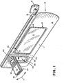
- Figure 1 is a perspective view of a vehicle visor incorporating a lighting means; and
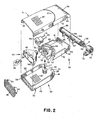
- Figure 2 is an enlarged, exploded view of the lighting means shown in Figure 1.
- Referring initially to Figure 1, there is shown a
visor 10 which has a body 11 which can be made of a moulded polymeric material of the type described in US-A-3,926,470. The visor body 11 includes a central rectangular recess for receiving a mirror andframe assembly 12 including amirror 13 and frame 14 surrounding the mirror and conventionally mounted within the visor body 11 on a side facing the vehicle occupant when the visor is in a lowered position, as shown in Figure 1. The visor assembly also includes apivot arm 16 mounted to anelbow mounting assembly 18 which can be of conventional construction to permit visor movement. Thevisor 10 can be upholstered in afabric 15 to match the vehicle interior and includes arectangular recess 20 extending through the visor body and incorporating a light. - The
recess 20 is a generally vertically extending, elongated, rectangular aperture surrounded by a mouldedpolymeric frame 22 having a forward facingflange 23 and a rearward facingflange 24 defining a frame into which apivoted light 30 which can be directed into a number of positions is mounted. The lighting includes alight housing assembly 25 which is pivotally coupled to amounting bracket assembly 50. Thelight housing assembly 25 pivots laterally (i.e. from side-to-side) with respect to the vehicle interior, as illustrated by arrow A in Figure 1, while the mounting bracket is pivotally coupled within therecess 20 to swing theentire light 30 from back to front through therecess 20 to either side of the visor, as illustrated by arrow B in Figure 1. - Referring now to Figure 2, the
light housing assembly 25 includes anupper housing shell 31 and alower housing shell 32 each of which are of substantially identical construction and include aU-shaped facing slot peripheral flange 27 of alight reflector 42. Thereflector 42 is generally concave with a reflective interior coating to direct light from alamp 43 outwardly through alens 35. Thelens 35 extends along the width of the rectangular first end of thelight housing assembly 25 and includes rearwardly projectinglocking tabs 36 extending over the ridges defining therecesses tabs 36 is provided byslots 28 formed in theperipheral flange 27 of thereflector 42. The opposite end of eachhousing half semicircular end sidewalls - A
light assembly 40 is mounted within thehousing shells light reflector 42, into which asocket 44 is mounted for receiving thelamp 43 mounted within the reflector and into thesocket 44. Thesocket 44 is electrically coupled to the vehicle's electrical system by means ofconductors mating sidewalls shells arcuate slot 39 extending over approximately a 90° angle.Edges sidewalls light assembly 40 as described below. Apivot pin 49 is integrally formed with and extends upwardly from thehousing shell 32 through acircular collar 21 integrally formed in alower mounting housing 52 which is mated with a corresponding and substantially identicalupper mounting housing 54 to form amounting bracket assembly 50. Thelower mounting housing 52 includes a generally semicircular,annular floor 53 bounded byarcuate wall sections vertical end walls 56 against which theedges light 30. This construction provides a pair of opposing,arcuate slots sidewalls mounting bracket assembly 50. - The
collar 21 is supported centrally within thefloor 53 to receive thepivot pin 49 extending upwardly from the lower housing shell 32 (a similar pivot structure is provided byhousings 31 and 54) and which is snuggly fitted within the internal diameter of thecollar 21 to be pivoted therein about the pivot axis C, shown in Figure 2, and remain in an adjusted pivoted position. Themounting housing halves sidewalls semicircular recesses pivot shaft 64. Themounting bracket assembly 50 including themounting housings pivot shaft 64 by means of integrallymoulded stops shaft 64 and fitted immediately inside andadjacent sidewalls shaft 64 is knurled atopposite ends 68 to fit within a pair of friction socket brackets 70 (one shown) which are secured by fastening screws which extend throughaperture 72 of eachbracket 70 and into the visor body. Theframe 22 surrounds therecess 20 and includesapertures 59 permitting the shaft 64 (Figure 1) to extend therethrough. Thus, the pivoting movement between the light assembly and the visor body occurs at the interface of the shaft ends 68 within thefixed brackets 70. The inner surface of thebracket 70 can also include one or more identations which cooperate with theends 68 of theshaft 64 to provide selected detent positions of adjustment of the light assembly about an arc of about 180° of movement. The bracket and pivot shaft may be formed to provide a holding detent for the stored position of the assembly flush with the visor body. - The
conductors aperture 69 formed in the wall of the hollow,cylindrical pivot shaft 64 and extend outwardly through one end, as best seen in Figure 2, to communicate with an on/off switch such that thelamp 43 can be selectively actuated for providing illumination from thelight 30. - Each of the
housing shells lamp 43. Thehousing shells sidewalls mounting housing sections light 30 can be moved from a stored position substantially flush and parallel with the visor body to an outwardly extending position. This extended position can be on either side of the visor body. Figure 1 shows the light extended on one side of the visor. Alternatively the light can be extended on the opposite- side of the visor (when the visor is in a stored position against the vehicle headliner) and pivoted to direct light away from the visor. The light also can be pivoted on thepivot pin 49 over approximately a 900 angle, as indicated by arrow A in Figure 1, to laterally adjust the direction of light emitted through thelens 35. Theconductors
Claims (9)
Applications Claiming Priority (2)
| Application Number | Priority Date | Filing Date | Title |
|---|---|---|---|
| US06/448,940 US4511954A (en) | 1982-12-13 | 1982-12-13 | Visor with auxiliary light |
| US448940 | 1989-12-11 |
Publications (3)
| Publication Number | Publication Date |
|---|---|
| EP0111426A2 true EP0111426A2 (en) | 1984-06-20 |
| EP0111426A3 EP0111426A3 (en) | 1984-11-21 |
| EP0111426B1 EP0111426B1 (en) | 1986-10-15 |
Family
ID=23782244
Family Applications (1)
| Application Number | Title | Priority Date | Filing Date |
|---|---|---|---|
| EP83307569A Expired EP0111426B1 (en) | 1982-12-13 | 1983-12-13 | A light for a vehicle visor |
Country Status (6)
| Country | Link |
|---|---|
| US (1) | US4511954A (en) |
| EP (1) | EP0111426B1 (en) |
| JP (1) | JPS59109425A (en) |
| CA (1) | CA1235404A (en) |
| DE (1) | DE3366878D1 (en) |
| ES (1) | ES527057A0 (en) |
Cited By (2)
| Publication number | Priority date | Publication date | Assignee | Title |
|---|---|---|---|---|
| EP0398275A2 (en) * | 1989-05-18 | 1990-11-22 | Eugen Zipperle Gmbh & Co. Kg | Sun visor for motor vehicles |
| DE202013007804U1 (en) * | 2013-09-03 | 2014-12-05 | GM Global Technology Operations LLC (n. d. Gesetzen des Staates Delaware) | Sun visor assembly for a vehicle and vehicle with the sun visor assembly |
Families Citing this family (41)
| Publication number | Priority date | Publication date | Assignee | Title |
|---|---|---|---|---|
| JPS6088408U (en) * | 1983-11-25 | 1985-06-18 | 株式会社ニフコ | lighting equipment |
| DE3427952A1 (en) * | 1984-07-28 | 1986-01-30 | Gebr. Happich Gmbh, 5600 Wuppertal | SUN VISOR FOR VEHICLES |
| US4628417A (en) * | 1985-12-09 | 1986-12-09 | Chrysler Motors Corporation | Combination dome/cargo lamp |
| US4734831A (en) * | 1986-05-28 | 1988-03-29 | Prince Corporation | Visor with concealed removable vanity mirror |
| US4733336A (en) * | 1986-06-26 | 1988-03-22 | Donnelly Corporation | Lighted/information case assembly for rearview mirrors |
| US4807096A (en) * | 1986-06-26 | 1989-02-21 | Donnelly Corporation | Interior light/carrier module for vehicles |
| US4760503A (en) * | 1986-09-26 | 1988-07-26 | Prince Corporation | Visor for a vehicle |
| US5078445A (en) * | 1986-09-26 | 1992-01-07 | Prince Corporation | Visor |
| DE3727346A1 (en) * | 1987-08-17 | 1989-03-02 | Happich Gmbh Gebr | Illuminating device for vehicles |
| DE3727455A1 (en) * | 1987-08-18 | 1989-03-02 | Happich Gmbh Gebr | Sunscreen for vehicles |
| DE3727587A1 (en) * | 1987-08-19 | 1989-03-02 | Happich Gmbh Gebr | Sun visor for vehicles |
| US4807093A (en) * | 1987-11-16 | 1989-02-21 | Prince Corporation | Two-way vanity mirror visor |
| SE467201B (en) * | 1988-04-29 | 1992-06-15 | Autopart Sweden Ab | SUN PROTECTION FOR MOTOR VEHICLE |
| US4912607A (en) * | 1989-04-17 | 1990-03-27 | Kocsi Mark D | Visor emergency lighting apparatus |
| GB2233295B (en) * | 1989-06-28 | 1993-05-12 | Austin Rover Group | A sun visor |
| SE9002133L (en) * | 1990-06-15 | 1991-12-16 | Autopart Sweden Ab | MIRROR AND LIGHTING UNIT FOR MOTOR VEHICLE |
| US5060124A (en) * | 1990-09-28 | 1991-10-22 | Alm Surgical Equipment, Inc. | Concealable birthing room light |
| US5081566A (en) * | 1990-12-13 | 1992-01-14 | Alm Surgical Equipment, Inc. | Concealable surgical light |
| US5178448A (en) * | 1991-09-13 | 1993-01-12 | Donnelly Corporation | Rearview mirror with lighting assembly |
| US5649756A (en) * | 1991-09-13 | 1997-07-22 | Donnelly Corporation | Rearview mirror with lighting assembly |
| US5283720A (en) * | 1992-06-26 | 1994-02-01 | Prince Corporation | Visor with illumination |
| US5428513A (en) * | 1993-11-17 | 1995-06-27 | Prince Corporation | Covered vanity mirror and flexible circuit |
| US5438491A (en) * | 1993-11-19 | 1995-08-01 | Jay Roberts Company | Vehicular sun visor assembly |
| US5564813A (en) * | 1994-03-30 | 1996-10-15 | United Technologies Automotive, Inc. | Sun visor lamp |
| US5564815A (en) * | 1994-06-29 | 1996-10-15 | Lightron Of Cornwall Incorporated | Adjustable light fixture |
| US5671996A (en) * | 1994-12-30 | 1997-09-30 | Donnelly Corporation | Vehicle instrumentation/console lighting |
| USD379546S (en) * | 1996-04-26 | 1997-05-27 | Lightron Of Cornwall Incorporated | Recessed adjustable light fixture |
| AU7583400A (en) * | 1999-09-17 | 2001-04-17 | Brightline, L.P. | Adjustable fluorescent lighting fixtures |
| US6257745B1 (en) | 1999-12-14 | 2001-07-10 | Daimlerchrysler Corporation | Flexible arm light for automobile overhead console |
| JP4908673B2 (en) * | 2000-10-05 | 2012-04-04 | 株式会社東海理化電機製作所 | Room mirror |
| JP4298931B2 (en) * | 2001-03-07 | 2009-07-22 | 株式会社テーアンテー | Vanity mirror |
| US7091843B1 (en) * | 2002-11-05 | 2006-08-15 | Rajiv Singh Lal | Functional and ornamental vehicle accessories |
| US7217017B2 (en) * | 2003-08-25 | 2007-05-15 | Johnson Controls Technology Company | Vanity for a vehicle |
| US7055983B1 (en) | 2004-06-17 | 2006-06-06 | Brooks & Baker Llc | Tackle and storage box with rotatable light |
| WO2006042051A2 (en) * | 2004-10-08 | 2006-04-20 | B/E Aerospace, Inc. | Lighting apparatus |
| US20070133219A1 (en) * | 2005-12-13 | 2007-06-14 | Brian Chaloult | Vehicle interior light assembly with removable flashlight |
| JP4628968B2 (en) * | 2006-01-30 | 2011-02-09 | 矢崎総業株式会社 | Vehicle sun visor |
| US8425094B2 (en) | 2010-06-09 | 2013-04-23 | Ford Global Technologies, Llc | Vehicle vanity and light assembly and visor having vanity and dome lighting |
| US9310037B2 (en) | 2012-02-08 | 2016-04-12 | Brightline, Inc. | Motorized lighting fixture with motor and light dimming control |
| USD757420S1 (en) | 2014-04-11 | 2016-05-31 | Mark Z. Gjelaj | Sun shield with solar powered light |
| US10093226B1 (en) * | 2017-08-09 | 2018-10-09 | Ford Global Technologies, Llc | Deployable vehicle light assembly |
Citations (5)
| Publication number | Priority date | Publication date | Assignee | Title |
|---|---|---|---|---|
| US2466454A (en) * | 1946-01-30 | 1949-04-05 | George H Logan | Illuminated automobile sun visor mirror |
| US3375364A (en) * | 1965-10-21 | 1968-03-26 | Donnelly Mirrors Inc | Visor-mirror assembly |
| FR2318046A1 (en) * | 1975-07-14 | 1977-02-11 | Prince Corp | ASSEMBLING A LENS HOOD AND MIRROR |
| US4421355A (en) * | 1981-07-23 | 1983-12-20 | Prince Corporation | Illuminated visor assembly |
| EP0096154A2 (en) * | 1982-06-12 | 1983-12-21 | Gebr. Happich GmbH | Sun visor, especially for vehicles |
Family Cites Families (7)
| Publication number | Priority date | Publication date | Assignee | Title |
|---|---|---|---|---|
| US2636979A (en) * | 1953-04-28 | |||
| US1456927A (en) * | 1922-04-14 | 1923-05-29 | David M Kumpf | Writing pad |
| FR1221782A (en) * | 1959-01-10 | 1960-06-03 | Advanced visor and caps or the like provided with this visor | |
| US3533648A (en) * | 1967-09-14 | 1970-10-13 | Arthur M Thieberger | Support for a lamp |
| US4049309A (en) * | 1976-02-06 | 1977-09-20 | Board Of Trustees Western Washington State College | Automotive vehicle |
| JPS5725405A (en) * | 1980-07-21 | 1982-02-10 | Teijin Ltd | Spinneret |
| US4470106A (en) * | 1983-04-06 | 1984-09-04 | Norton Larry G | Shop light |
-
1982
- 1982-12-13 US US06/448,940 patent/US4511954A/en not_active Expired - Fee Related
-
1983
- 1983-10-07 CA CA000438752A patent/CA1235404A/en not_active Expired
- 1983-11-07 ES ES527057A patent/ES527057A0/en active Granted
- 1983-11-30 JP JP58226729A patent/JPS59109425A/en active Granted
- 1983-12-13 EP EP83307569A patent/EP0111426B1/en not_active Expired
- 1983-12-13 DE DE8383307569T patent/DE3366878D1/en not_active Expired
Patent Citations (5)
| Publication number | Priority date | Publication date | Assignee | Title |
|---|---|---|---|---|
| US2466454A (en) * | 1946-01-30 | 1949-04-05 | George H Logan | Illuminated automobile sun visor mirror |
| US3375364A (en) * | 1965-10-21 | 1968-03-26 | Donnelly Mirrors Inc | Visor-mirror assembly |
| FR2318046A1 (en) * | 1975-07-14 | 1977-02-11 | Prince Corp | ASSEMBLING A LENS HOOD AND MIRROR |
| US4421355A (en) * | 1981-07-23 | 1983-12-20 | Prince Corporation | Illuminated visor assembly |
| EP0096154A2 (en) * | 1982-06-12 | 1983-12-21 | Gebr. Happich GmbH | Sun visor, especially for vehicles |
Cited By (4)
| Publication number | Priority date | Publication date | Assignee | Title |
|---|---|---|---|---|
| EP0398275A2 (en) * | 1989-05-18 | 1990-11-22 | Eugen Zipperle Gmbh & Co. Kg | Sun visor for motor vehicles |
| EP0398275A3 (en) * | 1989-05-18 | 1992-05-13 | Eugen Zipperle Gmbh & Co. Kg | Sun visor for motor vehicles |
| DE202013007804U1 (en) * | 2013-09-03 | 2014-12-05 | GM Global Technology Operations LLC (n. d. Gesetzen des Staates Delaware) | Sun visor assembly for a vehicle and vehicle with the sun visor assembly |
| GB2520126A (en) * | 2013-09-03 | 2015-05-13 | Gm Global Tech Operations Inc | A Sun Visor Assembly For A motor Vehicle And A Vehicle With A Sun Visor Assembly |
Also Published As
| Publication number | Publication date |
|---|---|
| JPS59109425A (en) | 1984-06-25 |
| EP0111426B1 (en) | 1986-10-15 |
| EP0111426A3 (en) | 1984-11-21 |
| CA1235404A (en) | 1988-04-19 |
| US4511954A (en) | 1985-04-16 |
| ES8503580A1 (en) | 1985-03-01 |
| ES527057A0 (en) | 1985-03-01 |
| DE3366878D1 (en) | 1986-11-20 |
| JPH0427045B2 (en) | 1992-05-08 |
Similar Documents
| Publication | Publication Date | Title |
|---|---|---|
| EP0111426B1 (en) | A light for a vehicle visor | |
| US4824159A (en) | Pivoted rotatable illuminated rear seat vanity mirror | |
| US4807093A (en) | Two-way vanity mirror visor | |
| US4075468A (en) | Visor and mirror assembly | |
| EP0117951B1 (en) | Visor cover assembly | |
| US6007222A (en) | Modular exterior rearview mirror assembly | |
| US6336737B1 (en) | Modular exterior rearview mirror assembly | |
| US4792884A (en) | Illuminated vanity mirror visor | |
| EP0079728A2 (en) | Illuminated mirror assembly | |
| EP0462087B1 (en) | Mirror and illumination unit for motor vehicles | |
| JPH0210726B2 (en) | ||
| EP0270508B1 (en) | Vehicle sun visor with illuminated mirror | |
| WO2000055009A8 (en) | Exterior mirror having an attachment member including an approach light | |
| JP2645451B2 (en) | Automotive sun visor | |
| GB2337321A (en) | Automobile headlamp comprising a floodlight lamp disposed above a reflector lamp | |
| US6746140B2 (en) | Rear-view mirror and interior lighting system | |
| US20060198123A1 (en) | Automotive visor with illuminated mirror assembly | |
| EP0314652B1 (en) | A sun visor assembly for motor vehicles, with an illuminated rear-view mirror | |
| US20050047160A1 (en) | Exterior rearview mirror assembly | |
| US5577792A (en) | Multiple visor system with aligned pivot axes | |
| US5975708A (en) | Visor with pivoting vanity mirror assembly | |
| JP2971708B2 (en) | High mount stop lamp | |
| US4910648A (en) | Illuminated visor mounting bracket | |
| JP3107901B2 (en) | Sun visor with mirror | |
| US20050174790A1 (en) | Interior illumination lamp |
Legal Events
| Date | Code | Title | Description |
|---|---|---|---|
| PUAI | Public reference made under article 153(3) epc to a published international application that has entered the european phase |
Free format text: ORIGINAL CODE: 0009012 |
|
| AK | Designated contracting states |
Designated state(s): DE FR GB IT |
|
| PUAL | Search report despatched |
Free format text: ORIGINAL CODE: 0009013 |
|
| AK | Designated contracting states |
Designated state(s): DE FR GB IT |
|
| 17P | Request for examination filed |
Effective date: 19850429 |
|
| ITF | It: translation for a ep patent filed |
Owner name: BARZANO' E ZANARDO ROMA S.P.A. |
|
| GRAA | (expected) grant |
Free format text: ORIGINAL CODE: 0009210 |
|
| AK | Designated contracting states |
Kind code of ref document: B1 Designated state(s): DE FR GB IT |
|
| REF | Corresponds to: |
Ref document number: 3366878 Country of ref document: DE Date of ref document: 19861120 |
|
| ET | Fr: translation filed | ||
| PLBE | No opposition filed within time limit |
Free format text: ORIGINAL CODE: 0009261 |
|
| STAA | Information on the status of an ep patent application or granted ep patent |
Free format text: STATUS: NO OPPOSITION FILED WITHIN TIME LIMIT |
|
| 26N | No opposition filed | ||
| PGFP | Annual fee paid to national office [announced via postgrant information from national office to epo] |
Ref country code: GB Payment date: 19911118 Year of fee payment: 9 |
|
| PGFP | Annual fee paid to national office [announced via postgrant information from national office to epo] |
Ref country code: FR Payment date: 19911212 Year of fee payment: 9 |
|
| ITTA | It: last paid annual fee | ||
| PG25 | Lapsed in a contracting state [announced via postgrant information from national office to epo] |
Ref country code: GB Effective date: 19921213 |
|
| GBPC | Gb: european patent ceased through non-payment of renewal fee |
Effective date: 19921213 |
|
| PG25 | Lapsed in a contracting state [announced via postgrant information from national office to epo] |
Ref country code: FR Effective date: 19930831 |
|
| REG | Reference to a national code |
Ref country code: FR Ref legal event code: ST |
|
| PGFP | Annual fee paid to national office [announced via postgrant information from national office to epo] |
Ref country code: DE Payment date: 19941223 Year of fee payment: 12 |
|
| PG25 | Lapsed in a contracting state [announced via postgrant information from national office to epo] |
Ref country code: DE Effective date: 19960903 |