EP0111332B1 - Method for the detection of data collisions in an optical data bus - Google Patents
Method for the detection of data collisions in an optical data bus Download PDFInfo
- Publication number
- EP0111332B1 EP0111332B1 EP83112418A EP83112418A EP0111332B1 EP 0111332 B1 EP0111332 B1 EP 0111332B1 EP 83112418 A EP83112418 A EP 83112418A EP 83112418 A EP83112418 A EP 83112418A EP 0111332 B1 EP0111332 B1 EP 0111332B1
- Authority
- EP
- European Patent Office
- Prior art keywords
- signal
- data
- time
- jam
- bits
- Prior art date
- Legal status (The legal status is an assumption and is not a legal conclusion. Google has not performed a legal analysis and makes no representation as to the accuracy of the status listed.)
- Expired
Links
Images


Classifications
-
- H—ELECTRICITY
- H04—ELECTRIC COMMUNICATION TECHNIQUE
- H04B—TRANSMISSION
- H04B10/00—Transmission systems employing electromagnetic waves other than radio-waves, e.g. infrared, visible or ultraviolet light, or employing corpuscular radiation, e.g. quantum communication
- H04B10/27—Arrangements for networking
- H04B10/278—Bus-type networks
-
- H—ELECTRICITY
- H04—ELECTRIC COMMUNICATION TECHNIQUE
- H04L—TRANSMISSION OF DIGITAL INFORMATION, e.g. TELEGRAPHIC COMMUNICATION
- H04L12/00—Data switching networks
- H04L12/28—Data switching networks characterised by path configuration, e.g. LAN [Local Area Networks] or WAN [Wide Area Networks]
- H04L12/44—Star or tree networks
Definitions
- the present invention relates to a method for detecting data collisions in an optical data bus according to the preamble of patent claim 1.
- Shade devices which implement a method of the type mentioned are proposed, for example, in the older European patent application EP-A-98 452, published on January 18, 1984. These methods are based on a level evaluation of the pulses arriving in a receiver or on a bit-wise comparison of the sent and received pulses.
- a distributed multimicrocomputer structure with an optical fiber bus system is known from Siemens research and development reports, vol. 9, no. 1, 1980, pp. 32-37, Berlin, in which a byte-wise information comparison is carried out to detect data collisions on the bus of the transmission signal is carried out with the reception signal of a subscriber.
- an asynchronous optical data bus is known, to which several stations with transmitters and receivers are connected, in which one station sends a JAM signal after a collision detection.
- the object of the invention is to provide a method of the type mentioned at the outset, which is distinguished by a considerably simplified circuit complexity compared to the above-mentioned proposed or known methods.
- Bus round trip time of a subscriber means the time in which the first bit that the subscriber has sent has returned to it.
- the time during which the sending subscriber queries whether data signals are coming in from the bus in his receiver is always less than the bus round trip time of this subscriber. This means that there is a duration in which no query is made and therefore no collisions can be detected. For certain applications, the probability of the collision not being recognized during the dead time may become too high.
- the procedure according to claim 2 is advantageously used.
- the method according to claim 3 or the method according to claim 4 is suitable as another collision detection method.
- the collisions can be recognized directly by all participants.
- this particularly simple method can only be implemented if the maximum power difference at any receiver does not exceed 3 dB.
- the combination of the method according to claim 3 and claim 4 is particularly suitable as another collision detection method.
- This method places practically no demands on the level dynamics or on fluctuations in the power level at the location of the receiver. Collisions only need to be detected by current transmitting participants, who in turn then determine this state through the JAM signals, i.e. Communicate signals that do not appear in the data signals to all non-sending participants.
- the method according to claim 3 or claim 4, in particular 3 and 4 form the basis for executing asynchronous optical data buses in which overhead line, collision and interrupt request (interrupt) can be recognized in all participants, which preferably consist of computers .
- overhead line, collision and interrupt request interrupt
- only the levels from own data are compared with levels of the sum of own data with interference data in the sending receivers in the event of collisions.
- the method according to the invention forms the basis for a simple control circuit for detecting collisions and overhead lines in passive optical buses, in particular star buses, with an asynchronous access method, which firstly does not have any special requirements for the passive star coupler with regard to the uniform power distribution on the coupler.
- Output provides and secondly allows different distances between the participants. So far, this has been achieved in the star bus by level evaluation of the pulses arriving in the receiver or by bit-wise comparison of the transmitted and received pulses.
- a level evaluation places high demands on the uniform distribution of the power at the star coupler output or on the receiver input, while a bit-wise comparison places high demands on the synchronization of the bits to be compared.
- the method according to the invention leads to a considerably simplified circuit complexity and the critical bottlenecks in the coupler and in the synchronization are eliminated. Depending on the time of data transfer or the different distances of the participants to the coupler etc., one of the participants involved in the data transmission always detects a collision.
- the inventive method according to claim 1 is also applicable to T-buses.
- the time constant ⁇ (i - 1 to 7) of the (retriggerable) monostable multivibrator i corresponds to the time of the unstable state of the multivibrator.
- the time constants specified with numbers refer to a bus length of 600 m. With a refractive index of the glass fiber core of 1.5, the transit time of a pulse is 3 ⁇ s on a glass fiber path of 600 m.
- An interrupt request is represented by a short positive pulse.
- the time between the start of useful data and the end of useful data falls within the duration of a validity signal represented by a logical "1".
- the data rate of the system is 16 Mbit / s.
- the scrambler required to scramble the data signals is designed so that no more than eight "1" or "0" appear at its output in a continuous sequence.
- the state "do not send data" is represented by an uninterrupted sequence of bits of the binary state "0" which is longer than eight bits.
- JAM signals are triggered by interrupt requests or collisions and comprise approximately 30 bits of binary state "1 in continuous succession.
- the bits of a participant's transmitter were compared to the bits entering the same participant's receiver.
- a delay circuit was provided in such a way that each bit of the transmitter coincides with the bit that comes from the same transmitter and has returned to the receiver of the sending subscriber after passing through the bus route.
- the delay element to be precisely timed was essentially replaced by an analog comparator which, together with the analog comparator always present in the actual receiver circuit, made it possible to determine collisions by evaluating the amplitudes of the bit streams.
- the level evaluation proposed in the earlier patent application mentioned can use the two comparators K1 and K2 there to detect collisions not only in the transmitting but also in all computers will.
- the threshold values in the threshold value comparators are selected such that only one comparator K1 and not also comparator K2 respond when there is only one bit stream, which indicates that there is no collision. However, if at least two bit streams overlap, the comparator K2 should also respond, which indicates a collision.
- JAM signals must be a bit pattern that clearly differs from user data and the "do not send data" state. Circuitry expenditure is required for the generation and detection of JAM signals.
- JAM signals are required. These must be able to be generated and recognized.
- some of the functions are represented only by logical block units. For example, required power drivers whose logical function corresponds to an inverter are partially represented by inverters.
- the time constant T6 is chosen to be somewhat (100ns ... 200ns) larger than the time constant ⁇ 3.
- the time constant of the retriggerable monostable multivibrator RMM5 of the JAM signal detection circuit is chosen more than twice the time required for the longest uninterrupted stream of '1' from the scrambler. For example, suppose that the scrambler cannot leave more than eight '1' or '0' in continuous order.
- the time constant T5 of the multivibrator RMM5 is then chosen to be 20 bits long, for example. Then a "positive edge change" always occurs during "sending data" within this time, so that when data is received Q - '0' remains. If a JAM signal now comes, for example a '1' for 30 bits, remains Q '0' for a maximum of 20 bits and then changes to the '1' state.
- JAM signals must be generated and recognized because collisions are only detected in sending computers.
- the collisions in transmitting computers are identified by delaying their own data by bitwise comparison.
- the collision in transmitting computers can also be determined by two comparators, as shown in the earlier patent application mentioned.
- collisions can be detected directly in all computers, ie without JAM signals, if the maximum power fluctuation at any receiver as a function of all transmitters does not exceed about 2 dB. This is done again with the help of two comparators. In this case, the line x 6 and the retriggerable monostable multivibrator RMM3 in FIG. 1 would be superfluous.
- FIGS. 2 to 4 show three control circuit units with which the circuit according to FIG. 1 can be constructed.
- the three units consist of the transmitter control shown in FIG. 2, the overhead line and collision detection shown in FIG. 3 and the receiver control shown in FIG.
- the transmitter control contains the unit A in FIG. 1 and the overhead line and collision detection unit B in FIG. 1.
- the transmitter control sends out data in the form of data packets, each of which contains so-called header bits in addition to the user data and possibly also contains dummy bits and end marking bits.
- the header bits and possibly also the dummy bits precede the useful data, while the end marking bits mark the end of the useful data.
- the header bits, dummy bits and user data which are limited in time by the leading and trailing edges of the validity signal, are sent out in a scrambled form by the transmitter control.
- the receiver controller recovers the user data from the scrambled data packet sent out by the transmitter controller. The same applies to the clock and the valid signal. In the event of a collision, it switches off the validity signal.
- the overhead line and collision detection also contains a collision detection circuit, which is based on the method variant c) in claim 1.
- this overhead line and collision detection circuit is used to construct the circuit according to FIG. 1, this also means that the collision detection principle has been changed because the collision detection circuit C in FIG. 1 is operated by the collision detection circuit C 'according to FIG. 3, which operates differently is replaced.
- the scrambler does not have an uninterrupted sequence of more than eight '0' or '1' in the scrambled data packet allows, header bits always starting with '1' are 14 bits long at the beginning of a data packet and the end of a data packet when transmitted via the bus consists of a '0' and eleven bits of the state '1'.
- the end-of-data pattern is generated by the transmitter control according to FIG. 2, namely by the unit D.
- the computer delivers the validity signal (valid signal) and the clock, which in addition to the actual data in the receiver Control must be recovered.
- the entire data packet sent by the LED consisting of header and dummy bits, the actual data and the end marking bits, each has the pattern shown in FIG. 5.
- the validity signal is also drawn there over the pattern of the data packet. The validity signal is not sent.
- the time constant ⁇ 1 of the retriggerable monostable multivibrator RMM1 in FIG. 3 is selected so that the state of the overhead line is displayed one bit later after the entire data packet has been received by all participants.
- a JAM signal consists of an uninterrupted stream of '1', not less than 24 bits long, which corresponds to a duration of 1.5 ⁇ s.
- the four inverters form the delay V2 and accordingly take into account the running time through the retriggerable monostable multivibrator RMM2, so that together with the time constant T2 - 1.2 ⁇ s it is ensured that x e - can become '1' only during the JAM signal .
- the monostable multivibrator MM7 forms a signal x 10 suitable for the computer from the JAM detection signal or the collision detection signal; Furthermore, a signal x 19 is generated by the JAM detection signal or the collision detection signal, which in the receiver control circuit according to FIG. 4 interrupts the validity signal e26 and the recovered data stream to the computer e 28 , the AND gate U z the counter Z opens again and the Counter Z now reset to '0' switches ready to count.
- X 17 becomes '1' at the start of the validity signal. X17 becomes '0' if a collision or a JAM signal is detected during the bus cycle time, or at the latest after the bus cycle time.
- the delay of the shift register R 3 in Figure 3 corresponds to the bus cycle time.
- the OR gate OD at the K input of the JK flip-flop F / F in FIG. 3 prevents more than one collision signal from being generated during the bus round trip time.
- the new collision detection circuit is simple, completely uncritical, reliable, etc. and requires no synchronization of the bits and practically no requirements for the power fluctuations.
- each participant Since the first bit of the data packet is always a '1', each participant only has to listen to the bus for incoming bits for the duration of one round, without losing efficiency in collision detection. A participant should only listen for a maximum of one round because he then receives his own data back.
- each sending subscriber listens into the bus, namely from the time of the start of his data, which coincides with the start of the valid signal.
- the listening time will always be shorter than the associated bus round trip time. This means that there is a dead time in which no listening takes place and therefore no collisions can be detected. For certain applications, the probability of the collision not being recognized during the dead time may become too high.
- the procedure is advantageously such that collisions are additionally determined during this dead time using another method for detecting collisions.
- the method based on the principle of "collision detection based on the principle of level evaluation with JAM signal generation (claim 3) is particularly suitable for this purpose, because this method places practically no demands on the level dynamics or the power fluctuations at the location of a receiver.
- one In order to be able to determine a collision in the dead time with certainty, one either selects the dead time shorter than the duration of a bit or one selects it immediately as one bit and leaves the data packets, especially the header bits of the data packets, with two bits of the binary state. Start 1 '.
- the listening times of the subscribers are also different.
- at least one participant will always detect a collision and generate the corresponding JAM signal if the query time corresponds exactly to the bus round trip time. There is no longer any need to distinguish between transmission errors and collisions.
- All collisions are also recognized in a ring bus if the listening time is selected between half and full round trip time.
- the circuits shown in FIGS. 2, 3 and 4 can be constructed using components from Texas Instruments, as can be seen, for example, from "The TTL Data Book", Texas Instrum., Fourth European Edition 1980.
- the designations LS 221, LS 123, S 112, LS 164, LS 21, LS 08, S 08, S 32, LS 04, S 04, LS 00, LS 02, LS 3 given in the figures mentioned mean the designations of the modules in the mentioned data book.
Description
Die vorliegende Erfindung betrifft ein Verfahren zur Erkennung von Datenkollisionen in einem optischen Datenbus nach dem Oberbegriff des Patentanspruchs 1.The present invention relates to a method for detecting data collisions in an optical data bus according to the preamble of
Schatteinrichtungen, die ein Verfahren der genannten Art realisieren, sind beispielsweise in der älteren europäischen Patentanmeldung EP-A-98 452, veröffentlich am 18.1.1984, vorgeschlagen. Diese Verfahren beruhen auf einer Pegelbewertung der in einem Empfänger einlaufenden Impulse oder auf einem bitweisen Vergleich der abgesandten und empfangenen Impulse.Shade devices which implement a method of the type mentioned are proposed, for example, in the older European patent application EP-A-98 452, published on January 18, 1984. These methods are based on a level evaluation of the pulses arriving in a receiver or on a bit-wise comparison of the sent and received pulses.
In Fifth Topical Meeting on Optical Fiber Communications, Phoenix, Arizona, 13.-15. April 1982, S. 22, 23, IEEE, New York, USA, ist ein Stern-Repeater beschrieben, bei dem eine auf einer Pegelüberwachung fußende Erkennung von Datenkollisionen durchgeführt wird.In Fifth Topical Meeting on Optical Fiber Communications, Phoenix, Arizona, 13-15. April 1982, pp. 22, 23, IEEE, New York, USA, describes a star repeater in which detection of data collisions based on level monitoring is carried out.
Aus Siemens Forschungs- und Entwicklungsberichte, Bd. 9, Nr. 1, 1980, S. 32-37, Berlin, ist eine verteilte Multimikrocomputerstruktur mit einem Lichtwellenleiter-Bussystem bekannt, bei der zur Erkennung von Datenkollisionen auf den Bus ein Byte-weiser Informationsvergleich des Sendesignals mit dem Empfangssignal eines Teilnehmers durchgeführt wird.A distributed multimicrocomputer structure with an optical fiber bus system is known from Siemens research and development reports, vol. 9, no. 1, 1980, pp. 32-37, Berlin, in which a byte-wise information comparison is carried out to detect data collisions on the bus of the transmission signal is carried out with the reception signal of a subscriber.
Aus Communications of the ACM, Bd. 19, Nr. 7, Juli 1976, S. 395-404, New York, ist ein asynchron arbeitender optischer Datenbus, an den mehrere Stationen mit Sendern und Empfängern angeschlossen sind, bekannt, bei dem eine Station nach einer Kollisionserkennung ein JAM-Signal aussendet.From Communications of the ACM, Vol. 19, No. 7, July 1976, pp. 395-404, New York, an asynchronous optical data bus is known, to which several stations with transmitters and receivers are connected, in which one station sends a JAM signal after a collision detection.
Aufgabe der Erfindung ist es, ein Verfahren der eingangs genannten Art anzugeben, das sich im Vergleich zu den obengenannten vorgeschlagenen oder bekannten Verfahren durch einen erheblich vereinfachten schaltungstechnischen Aufwand auszeichnet.The object of the invention is to provide a method of the type mentioned at the outset, which is distinguished by a considerably simplified circuit complexity compared to the above-mentioned proposed or known methods.
Diese Aufgabe wird durch die im kennzeichnenden Teil des Patentanspruchs 1 angegebenen Merkmale gelöst.This object is achieved by the features specified in the characterizing part of
Bus-Umlaufzeit eines Teilnehmers bedeutet die Zeit, in der das erste Bit, das der Teilnehmer ausgesandt hat, wieder bei ihm eingelaufen ist.Bus round trip time of a subscriber means the time in which the first bit that the subscriber has sent has returned to it.
Aus praktischen und logischen Gründen fällt die Zeit, während der sendende Teilnehmer abfragt, ob in seinem Empfänger Datensignale aus dem Bus einlaufen, immer kleiner aus als die Bus-Umlaufzeit dieses Teilnehmers. Dies bedeutet, daß man eine Dauer hat, in der nicht abgefragt wird und daher auch keine Kollisionen erkannt werden können. Für gewisse Anwendungsfälle kann die Wahrscheinlichkeit für die Nichterkennung der Kollision während der Totzeit zu hoch werden.For practical and logical reasons, the time during which the sending subscriber queries whether data signals are coming in from the bus in his receiver is always less than the bus round trip time of this subscriber. This means that there is a duration in which no query is made and therefore no collisions can be detected. For certain applications, the probability of the collision not being recognized during the dead time may become too high.
Um auch während der Totzeit Kollisionen erkennen zu können, wird vorteilhafterweise gemäß Anspruch 2 vorgegangen.In order to be able to detect collisions even during the dead time, the procedure according to
Als anderes Kollisions-Erkennungsverfahren eignet sich das Verfahren nach Anspruch 3 oder auch das Verfahren nach Anspruch 4.The method according to
Bei Verfahren nach Anspruch 4 können die Kollisionen direkt von allen Teilnehmern erkannt werden. Dieses besonders einfache Verfahren ist allerdings nur realisierbar, wenn die maximale Leistungsdifferenz an jedem beliebigen Empfänger 3 dB nicht überschreitet.In the method according to claim 4, the collisions can be recognized directly by all participants. However, this particularly simple method can only be implemented if the maximum power difference at any receiver does not exceed 3 dB.
Besonders geeignet als anderes Kollisions-Erkennungsverfahren ist die Kombination aus dem Verfahren nach Anspruch 3 und Anspruch 4. Dieses Verfahren stellt praktisch keine Anforderungen an die Pegeldynamik oder an Schwankungen der Leistungspegel am Ort der Empfänger. Kollisionen brauchen nur durch augenblicklich sendende Teilnehmer festgestellt werden, die dann ihrerseits diesen Zustand durch die JAM-Signale, d.h. Signale, die unter den Datensignalen nicht vorkommen, allen nicht sendenden Teilnehmern mitteilen.The combination of the method according to
Die Verfahren nach Anspruch 3 oder Anspruch 4, insbesondere 3 und 4, bilden die Grundlage für Ausführungen von asynchron arbeitenden optischen Datenbussen, in denen Freileitung, Kollision und Unterbrechungs-Anforderung (Interrupt) in allen Teilnehmern, die vorzugsweise aus Rechnern bestehen, erkannt werden können. Bei den Verfahren nach Anspruch 3 und 4 werden in den sendenden Empfängern im Falle von Kollisionen immer nur die Pegel aus eigenen Daten mit Pegeln der Summe aus eigenen Daten mit Stördaten verglichen.The method according to
Das erfindungsgemäße Verfahren nach Anspruch 1 bildet die Grundlage für eine einfache Steuerschaltung zur Erkennung von Kollisionen und Freileitung in passiven otpischen Bussen, insbesondere Stern-Bussen, mit asynchronem Zugriffsverfahren, die erstens keine speziellen Anforderungen an den passiven Sternkoppler hinsichtlich der Leistungs-Gleichverteilung am Koppler-Ausgang stellt und zweitens beliebig unterschiedliche Entfernungen zwischen den Teilnehmern zuläßt. Bislang wurde dies im Sternbus durch die Pegelbewertung der im Empfänger einlaufenden Impulse oder durch den bitweisen Vergleich der ausgesandten und empfangenen Impulse erreicht.The method according to the invention forms the basis for a simple control circuit for detecting collisions and overhead lines in passive optical buses, in particular star buses, with an asynchronous access method, which firstly does not have any special requirements for the passive star coupler with regard to the uniform power distribution on the coupler. Output provides and secondly allows different distances between the participants. So far, this has been achieved in the star bus by level evaluation of the pulses arriving in the receiver or by bit-wise comparison of the transmitted and received pulses.
Es sei darauf hingewiesen, daß eine Pegelbewertung hohe Anforderungen an die Gleichverteilung der Leistung am Stern-Koppler-Ausgang bzw. am Empfänger-Eingang stellt, während 30 ein bitweiser Vergleich hohe Anforderungen an die Synchronisation der zu vergleichenden Bits stellt.It should be noted that a level evaluation places high demands on the uniform distribution of the power at the star coupler output or on the receiver input, while a bit-wise comparison places high demands on the synchronization of the bits to be compared.
Demgegegenüber führt das erfindungsgemäße Verfahren nach Anspruch 1 zu einem erheblich vereinfachten schaltungstechnischen Aufwand und die kritischen Engpässe beim Koppler und bei der Synchronisation entfallen. Je nach Zeitpunkt des Datenabsetzens oder der verschiedenen Entfernungen der Teilnehmer zum Koppler usw. stellt immer einer der am Datensenden beteiligten Teilnehmer eine Kollision fest. Das erfindungsgemäße Verfahren nach Anspruch 1 ist auch auf T-Busse anwendbar.In contrast, the method according to the invention leads to a considerably simplified circuit complexity and the critical bottlenecks in the coupler and in the synchronization are eliminated. Depending on the time of data transfer or the different distances of the participants to the coupler etc., one of the participants involved in the data transmission always detects a collision. The inventive method according to
Bevorzugte und vorteilhafte Ausgestaltungen der im Anspruch 1 angegebenen Verfahren und bevorzugte spezielle Schaltungen zur Durchführung solcher Verfahren oder spezieller Verfahrensschritte gehen aus den Unteransprüchen hervor.Preferred and advantageous configurations the method specified in
Die Erfindung wird prinzipiell und auch beispielhaft anhand der Figuren in der folgenden Beschreibung näher erläutert. Von den Figuren zeigen:
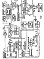
Figur 1 ein Blockschaltbild einer Schaltung zur Kollisions- und Freileitungserkennung, die durch die gestrichelt umrahmten Blockeinheiten A, B und C erweitert ist, von denen die Einheit A zur Erzeugung eines JAM-Signals in Abhängigkeit von einem Kollisionssignal dient, die Einheit B eine sogenannte JAM-Signal-Erkennungsschaltung und C die Kollisions-Erkennungsschaltung darstellt;Figur 2 ein Schaltbild einer in der Schaltung nachFigur 1 verwendbaren Sendersteuerung, die mit im Handel erhältlichen logischen Bausteinen aufgebaut ist,Figur 3 eine Schaltung zur Erkennung der Freileitung und von Kollisionen, die auf der Verfahrensversion c) basiert und mit im Handel erhältlichen logischen Bausteinen aufgebaut ist,- Figur 4 mit im Handel erhältlichen logischen Bausteinen aufgebaute Empfänger-Steuerschaltung, die im folgenden nur soweit beschrieben wird, wie es für das Zusammenwirken mit der Schaltung nach
Figur 3 erforderlich ist. - Figur 5 schematisch das Bitmuster eines Datenpakets und ein Gültigkeitssignal.
- Figure 1 is a block diagram of a circuit for collision and overhead line detection, which is expanded by the dashed-framed block units A, B and C, of which unit A is used to generate a JAM signal depending on a collision signal, unit B a so-called JAM Signal detection circuit and C represents the collision detection circuit;
- FIG. 2 shows a circuit diagram of a transmitter control that can be used in the circuit according to FIG. 1 and is constructed using commercially available logic modules,
- FIG. 3 shows a circuit for the detection of the overhead line and of collisions, which is based on the method version c) and is constructed with logic modules available on the market,
- FIG. 4 with receiver control circuit built up in commercially available logic modules, which is described in the following only to the extent necessary for the interaction with the circuit according to FIG. 3.
- Figure 5 schematically shows the bit pattern of a data packet and a validity signal.
In den verschiedenen Figuren sind Elemente, die einander entsprechen, mit gleichen Bezugszeichen versehen.In the various figures, elements that correspond to one another are provided with the same reference symbols.
Für die nachfolgende Beschreibung gilt folgendes: Die Zeitkonstante η (i - 1 bis 7) des (retriggerbaren) monostabilen Multivibrators i, kurz bezeichnet mit (R.) M.M.i, entspricht der Zeit des instabilen Zustandes des Multivibrators.The following applies to the following description: The time constant η (i - 1 to 7) of the (retriggerable) monostable multivibrator i, abbreviated to (R.) M.M.i, corresponds to the time of the unstable state of the multivibrator.
Die mit Zahlen angegebenen Zeitkonstanten beziehen sich auf eine Buslänge von 600 m. Bei einem Brechungsindex des Glasfaserkerns von 1,5 beträgt auf einer Glasfaserstrecke von 600 m die Laufzeit eines Impulses 3 µs.The time constants specified with numbers refer to a bus length of 600 m. With a refractive index of the glass fiber core of 1.5, the transit time of a pulse is 3 µs on a glass fiber path of 600 m.
Eine Unterbrechungs-Anforderung wird durch einen kurzen positiven Impuls dargestellt.An interrupt request is represented by a short positive pulse.
Die Zeit zwischen Nutzdaten-Anfang und Nutzdaten-Ende fällt in die Dauer eines durch eine logische "1" dargestellten Gültigkeitssignals.The time between the start of useful data and the end of useful data falls within the duration of a validity signal represented by a logical "1".
Die Datenrate des Systems betrage 16 Mbit/s. Der zum Verwürfeln der Datensignale notwendige Scrambler sei so ausgelegt, daß an seinem Ausgang nicht mehr als acht "1" bzw. "0" in ununterbrochener Folge erscheinen.The data rate of the system is 16 Mbit / s. The scrambler required to scramble the data signals is designed so that no more than eight "1" or "0" appear at its output in a continuous sequence.
Der Zustand "keine Daten senden" wird durch eine ununterbrochene Folge von Bits des Binärzustandes "0" die länger als acht Bits ist, dargestellt.The state "do not send data" is represented by an uninterrupted sequence of bits of the binary state "0" which is longer than eight bits.
JAM-Signale werden durch Unterbrechungs-Anforderungen oder Kollisionen ausgelöst, und umfassen etwa 30 Bits des Binärzustandes "1 in ununterbrochener Folge.JAM signals are triggered by interrupt requests or collisions and comprise approximately 30 bits of binary state "1 in continuous succession.
In den vorgeschlagenen Schaltungen, wie sie in der genannten älteren Patentanmeldung ausführlich dargestellt sind, ist davon ausgegangen,daß
- 1. Datenanfang und -ende der vom Rechner gelieferten Daten jeweils durch Impulse auf einer eigenen Leitung angezeigt wurden;
- 2. Kollisionen nur in den sendenden Rechnern erkannt werden mußten, und
- 3. Unterbrechungs-Anforderungen nicht erkannt werden mußten.
- 1. The beginning and end of the data supplied by the computer were each indicated by pulses on a separate line;
- 2. Collisions only had to be recognized in the sending computers, and
- 3. Interruption requests did not have to be recognized.
Die Bits des Senders eines Teilnehmers wurden mit den Bits verglichen, die in den Empfänger des gleichen Teilnehmers einlaufen. Es war eine Verzögerungsschaltung vorgesehen, derart, daß jedes Bit des Senders mit demjenigen Bit zeitlich zusammenfällt, das vom gleichen Sender kommt und nach Durchlaufen der Busstrecke zum Empfänger des sendenden Teilnehmers zurückgekehrt ist. In einer anderen Schaltungsversion wurde im wesentlichen das zeitlich genau abzustimmende Verzögerungsglied durch einen Analog-Komparator ersetzt, der es zusammen mit dem im eigentlichen Empfängerkreis stets vorhandenen Analog-Komparator ermöglichte, durch Auswertung der Amplituden der Bitströme Kollisionen festzustellen.The bits of a participant's transmitter were compared to the bits entering the same participant's receiver. A delay circuit was provided in such a way that each bit of the transmitter coincides with the bit that comes from the same transmitter and has returned to the receiver of the sending subscriber after passing through the bus route. In another circuit version, the delay element to be precisely timed was essentially replaced by an analog comparator which, together with the analog comparator always present in the actual receiver circuit, made it possible to determine collisions by evaluating the amplitudes of the bit streams.
Die Anforderungen an die Kollisions- und Freileitungsschaltung werden beim hier beschriebenen Vorschlag im wesentlichen in drei Punkten verschärft. Bei diesem Vorschlag sind die folgenden drei abgeänderten Forderungen berücksichtigt.
- 1. Daten-Anfang und -Ende sollen nicht mehr durch zwei getrennte Leitungen bzw. "Trigger-Impulse" angezeigt werden, sondern durch einen Impuls, in dessen Dauer das Datensenden, d.h. das Senden der eigentlichen Daten oder Nutzdaten fällt. Dieser Impuls ist, wie bereits erwähnt, als Gültigkeitssignal bezeichnet.
- 2. Kollisionen sollen in allen Rechnern erkannt werden, und nicht wie bisher, nur in sendenden Rechnern.
- 3. Das system soll auch Unterbrechungs-Anforderungen erkennen.
- 1. The beginning and end of the data should no longer be indicated by two separate lines or "trigger pulses", but by an impulse during which the data transmission, ie the transmission of the actual data or user data, falls. As already mentioned, this pulse is referred to as a valid signal.
- 2. Collisions should be recognized in all computers and not, as previously, only in sending computers.
- 3. The system should also recognize interrupt requests.
Was die zweite Forderung anbelangt, so sind zwei Realisierungen zu unterscheiden.As far as the second requirement is concerned, two realizations can be distinguished.
I. Wenn die maximalen Leistungsschwankungen bei irgendeinem Empfänger etwa 3 dB, vorzugsweise 2 dB, nicht überschreiten, können mit der in der genannten älteren Patentanmeldung vorgeschlagenen Pegelbewertung über die beiden dortigen Komparatoren K1 und K2 Kollisionen nicht nur in den sendenden, sondern allen Rechnern direkt erkannt werden. Die Schwellwerte in den Schwellwertkomparatoren werden so gewählt, daß beim Vorhandensein nur eines Bitstromes nur der Komparator K1 und nicht auch der Komparator K2 ansprechen, wodurch angezeigt wird, daß keine Kollision vorhanden ist. Überlagern sich jedoch mindestens zwei Bitströme, so soll auch der Komparator K2 ansprechen, wodurch eine Kollision angezeigt wird. Eine eindeutige Unterscheidung zwischen Kollision und Nicht-Kollision ist bei diesem Prinzip nur möglich, wenn die Leistungsschwankungen am Empfänger nicht so groß sind, daß die Summe der Amplituden (am Ausgang des Verstärkers) zweier Bitströme kleiner oder gleich der Amplitude eines Bitstroms werden kann. Ein JAM-Signal ist bei diesem Verfahren nicht nötig.I. If the maximum power fluctuations in any receiver do not exceed about 3 dB, preferably 2 dB, the level evaluation proposed in the earlier patent application mentioned can use the two comparators K1 and K2 there to detect collisions not only in the transmitting but also in all computers will. The threshold values in the threshold value comparators are selected such that only one comparator K1 and not also comparator K2 respond when there is only one bit stream, which indicates that there is no collision. However, if at least two bit streams overlap, the comparator K2 should also respond, which indicates a collision. A clear distinction between collision and non-collision is only possible with this principle if the power fluctuations at the receiver are not so great that the sum of the amplitudes (at the amplifier output) of two bit streams can be less than or equal to the amplitude of a bit stream. A JAM signal is not necessary with this method.
II. Wenn die Busstrecke mit dem Stern-Koppler diese Bedingung an die Leistungspegel nicht erfüllt, können Kollisionen nur in den sendenden Rechnern erkannt werden. Über JAM-Signale muß die Feststellung einer Kollision allen Rechnern mitgeteilt werden. JAM-Signale müssen ein Bitmuster sein, das sich eindeutig von Nutzdaten und dem Zustand "nicht Daten senden" unterscheidet. Für die Erzeugung und Erkennung von JAM-Signalen ist schaltungstechnischer Aufwand erforderlich.II. If the bus route with the star coupler does not meet this condition regarding the power level, collisions can only be detected in the sending computers. The detection of a collision must be communicated to all computers via JAM signals. JAM signals must be a bit pattern that clearly differs from user data and the "do not send data" state. Circuitry expenditure is required for the generation and detection of JAM signals.
In dem folgenden ausführlich beschriebenen Fall gemäß Figur 7 wird davon ausgegangen, daß JAM-Signale benötigt werden. Diese müssen erzeugt und erkannt werden können. In den folgenden Ausführungen ist vorausgesetzt, daß teilweise die Funktionen nur durch logische Blockeinheiten dargestellt sind. So werden beispielsweise benötigte Leistungstreiber, deren logische Funktion einem Inverter entspricht, teilweise durch Inverter dargestellt.In the following case described in detail according to FIG. 7, it is assumed that JAM signals are required. These must be able to be generated and recognized. In the following explanations it is assumed that some of the functions are represented only by logical block units. For example, required power drivers whose logical function corresponds to an inverter are partially represented by inverters.
In der Figur 7 ist das Zusammenspiel der logischen Blockeinheiten dargestellt.The interplay of the logical block units is shown in FIG.
Freileitungs-Erkennung:
- Die Schaltung zur Erkennung der Freileitung, d.h. des Zustandes, bei dem der Bus frei ist von Datensignalen, ist die gleiche wie in der genannten älteren Patentanmeldung. Die Zeitkonstante τ1 des das Freileitungssignal erzeugenden retriggerbaren monostabilen Multivibrators R.M.M.1 wird im hier beschriebenen Fall noch etwa 5 µs lang gewählt. Dadurch wird ausgeschlossen, daß lange ununterbrochene Folgen von Bits des Binärzustandes '1', wie sie z. B. in einem JAM-Signal vorliegen, ein Freileitungs-Signal '1' erzeugen. Ist nämlich τ1 nicht groß genug, so wird der Ausgang Ö des Multivibrators R.M.M.1 bei '1'-Folgen, die länger als τ1 sind, '1', weil in der '1'-Folge kein positiver Flankenwechsel bzw. keine positive Flanke stattfinden bzw. auftreten kann.
- The circuit for recognizing the overhead line, ie the state in which the bus is free of data signals, is the same as in the earlier patent application mentioned. The time constant τ 1 of the retriggerable monostable multivibrator RMM1 that generates the overhead line signal is selected for about 5 μs in the case described here. This rules out that long uninterrupted sequences of bits of the binary state '1', as z. B. present in a JAM signal, generate an overhead line signal '1'. If τ 1 is not large enough, the output Ö of the multivibrator RMM1 becomes '1' for '1' sequences that are longer than τ 1 because there is no positive edge change or no positive edge in the '1' sequence can take place or occur.
Erkennung von Kollisionen in sendenden Rechnern und Erzeugung eines JAM-Signals:Detection of collisions in sending computers and generation of a JAM signal:
Wie in der genannten älteren Patentanmeldung ausführlich erläutert, wird in einem sendenden Rechner bei einer Kollision x7 = '1'. Dadurch wird x"18 = x18 = '1' (x18 entspricht dem Ausgang x15 in Figur 2 der älteren Patentanmeldung). Durch den monostabilen Multivibrator M.M.4 wird x19 = '0'. Wenn x7 = '1' wird, ist x'22 = '1'. Dieses Kollisionssignal x'22 schaltet x17 auf '0' ab, so daß x'11 = '1' wird, und '1' bleibt (Maßnahme, die im Rechner vorgenommen wird). Solange x,9 - '0' ist (T4), sendet die LED '1' aus. Dieses JAM-Signal wird etwa 30 Bits lang gewählt. Danach sind x19 = x'11 = '1' und die LED sendet nur noch '0'. Die Zeitkonstante T6 wird etwas (100ns...200ns) größer als die Zeitkonstante τ3 gewählt. Wenn nämlich das durch eine Kollisions-Erkennung erzeugte JAM-Signal nach Durchlaufen der Busstrecke wieder an den Entstehungsort zurückkommt, soll verhindert werden, daß erneut ein JAM-Signal erzeugt wird. Das zurückkommende JAM-Signal erzeugt jedoch möglicherweise eine Kollision (x7 = '1'). Solange x3 = '1' ist,.muß x18 durch eine entsprechende Zeitkonstante τ6 auf '1' bleiben, damit x19 nicht wieder nach '0' geht und ein neuerliches JAM-Signal auslöst.As explained in detail in the older patent application mentioned, in a sending computer, x 7 = '1' in a collision. As a result, x " 18 = x 18 = '1' (x 18 corresponds to the output x 15 in FIG. 2 of the older patent application). The monostable multivibrator MM4 makes x 19 = '0'. If x 7 = '1', is x '22 =' 1. This collision signal x '22 switches x 17 off to' 0 ', so that x' 11 = '1', and remains '1' (measure which is carried out in the computer) x, 9 - '0' is ( T4 ), the LED sends out '1.' This JAM signal is chosen to be about 30 bits long, after which x 19 = x '11 =' 1 'and the LED only sends' The time constant T6 is chosen to be somewhat (100ns ... 200ns) larger than the time constant τ 3. If the JAM signal generated by a collision detection comes back to the place of origin after passing through the bus route, it should be prevented A JAM signal is generated again, but the returning JAM signal may produce a collision (x 7 = '1'). As long as x 3 = '1', x 18 must be set to '1' by a corresponding time constant τ 6 . stay so x 19 does not go back to '0' and triggers a new JAM signal.
Interrupt-Behandlung:
- Beim Auftreten eines Interrupt- bzw. eines Unterbrechungs-Impulses (ein Rechner möchte den derzeitigen Zustand unterbrechen und möglicherweise selber senden) wird x"18 = '1' und es wird x20 = '1' für die Zeit, die der Zeitkonstanten τ4 entspricht, d.h. die LED erzeugt ein JAM-Bignal. Gleichzeitig mit dem Interrupt-Impuls wird x = '0' geschaltet (und bleibt'0'). Nach dem JAM-Signal ist die LED (Licht emittierende Diode) abgeschaltet.
- If an interrupt or an interrupt pulse occurs (a computer wants to interrupt the current state and possibly send it itself), x " 18 = '1' and x 20 = '1' for the time corresponding to the time constant τ 4 corresponds, ie the LED generates a JAM signal. Simultaneously with the interrupt pulse, x = '0' is switched (and remains '0'). After the JAM signal, the LED (light-emitting diode) is switched off.
Erkennung des JAM-Signals:
- Die Schaltung zur Erkennung der JAM-Signale entspricht, grob gesagt, einem Zähler, der erkennt, daß z. B. mehr als 30 Bits des Binärzustandes '1' in ununterbrochener Reihenfolge aus dem Komparator K1 des Empfängers ausgetreten sind. Dieser Zustand ist eindeutig dem JAM-Signal zugeordnet.
- The circuit for detecting the JAM signals corresponds, roughly speaking, to a counter that detects that, for. B. more than 30 bits of the binary state '1' have emerged in an uninterrupted order from the comparator K1 of the receiver. This state is clearly assigned to the JAM signal.
Die Zeitkonstante des retriggerbaren monostabilen Multivibrators R.M.M.5 der JAM-Signal-Erkennungsschaltung wird mehr als zweimal die Zeit gewählt, die für den längsten ununterbrochenen Strom von '1' aus dem Scrambler benötigt wird. Es sei beispielsweise angenommen, daß den Scrambler nicht mehr als acht '1' bzw. '0' in ununterbrochener Reihenfolge verlassen können. Die Zeitkonstante T5 des Multivibrators R.M.M.5 wird dann beispielsweise 20 Bits lang gewählt. Dann tritt bei "Senden von Daten" innerhalb dieser Zeit immer ein positiver Flankenwechsel auf, so daß bei Datenempfang
Kollisions-Erkennung in nicht sendenden Rechnern:
- Nicht sendende Rechner können in der in
Figur 1 dargestellten Behaltung Kollisionen nur durch JAM-Signale erkennen, die von sendenden Rechnern stammen, in denen Kollisionen erkannt worden sind.
- In the container shown in FIG. 1, non-sending computers can only detect collisions by means of JAM signals which originate from sending computers in which collisions have been detected.
Es sei noch einmal hervorgehoben, daß in dem ausführlich dargelegten Beispiel nach Figur 7 JAM-Signale erzeugt und.erkannt werden müssen, weil Kollisionen nur in sendenden Rechnern festgestellt werden. Weiterhin ist in der Schaltung nach Figur 1 angenommen, daß die Erkennung der Kollisionen in sendenden Rechnern über die Verzögerung der eigenen Daten durch bitweisen Vergleich erfolgt. Die Feststellung der Kollision in sendenden Rechnern kann auch durch zwei Komparatoren erfolgen, so wie es in der genannten älteren Patentanmeldung dargestellt ist. Schließlich können im einfachsten Fall Kollisionen in allen Rechnern direkt, d.h. ohne JAM-Signale erkannt werden, wenn die maximale Leistungsschwankung an irgendeinem Empfänger als Funktion aller Sender etwa 2 dB nicht überschreitet. Das wird wieder mit Hilfe zweier Komparatoren durchgeführt. In diesem Fall würden die Leitung x6 und der retriggerbare monostabile Multivibrator R.M.M.3 in Figur 1 überflüssig.It should be emphasized once again that in the example shown in detail in FIG. 7, JAM signals must be generated and recognized because collisions are only detected in sending computers. Furthermore, it is assumed in the circuit according to FIG. 1 that the collisions in transmitting computers are identified by delaying their own data by bitwise comparison. The collision in transmitting computers can also be determined by two comparators, as shown in the earlier patent application mentioned. Finally, in the simplest case, collisions can be detected directly in all computers, ie without JAM signals, if the maximum power fluctuation at any receiver as a function of all transmitters does not exceed about 2 dB. This is done again with the help of two comparators. In this case, the line x 6 and the retriggerable monostable multivibrator RMM3 in FIG. 1 would be superfluous.
In den Figuren 2 bis 4 sind drei Steuer-Schaltungs-Einheiten angegeben, mit denen die Schaltung gemäß Figur 1 aufgebaut werden kann.FIGS. 2 to 4 show three control circuit units with which the circuit according to FIG. 1 can be constructed.
Die drei Einheiten bestehen aus der in Figur 2 dargestellten Sender-Steuerung, der in Figur 3 dargestellten Freileitungs- und Kollisionserkennung und aus der in Figur 4 dargestellten Empfänger-Steuerung.The three units consist of the transmitter control shown in FIG. 2, the overhead line and collision detection shown in FIG. 3 and the receiver control shown in FIG.
Die Sender-Steuerung enthält die genannte Einheit A in Figur 1 und die Freileitungs- und Kollisions-Erkennung genannte Einheit B in Figur 1. Die Sender-Steuerung sendet Daten in Form von Datenpaketen aus, von den jedes neben den Nutzdaten sog. Kopf-Bits und gegebenenfalls auch Dummy-Bits sowie Ende-Markierungsbits enthält. Die Kopf-Bits und gegebenenfalls auch die Dummy-Bits sind den Nutzdaten vorangestellt, während die Ende-Markierungsbits das Ende der Nutzdaten markieren. Die Kopf-Bits, Dummy-Bits und Nutzdaten, die durch die Vorderflanke und Rückflanke des Gültigkeitssignals zeitlich begrenzt sind, werden von der Sender-Steuerung in verwürfelter Form ausgesandt.The transmitter control contains the unit A in FIG. 1 and the overhead line and collision detection unit B in FIG. 1. The transmitter control sends out data in the form of data packets, each of which contains so-called header bits in addition to the user data and possibly also contains dummy bits and end marking bits. The header bits and possibly also the dummy bits precede the useful data, while the end marking bits mark the end of the useful data. The header bits, dummy bits and user data, which are limited in time by the leading and trailing edges of the validity signal, are sent out in a scrambled form by the transmitter control.
Die Empfänger-Steuerung gewinnt aus dem von der Sender-Steuerung ausgesandten verwürfeiten Datenpaket die Nutzdaten zurück. Das gleiche gilt für den Takt und das Gültigkeitssignal. Bei Kollision schaltet sie das Gültigkeitssignal ab.The receiver controller recovers the user data from the scrambled data packet sent out by the transmitter controller. The same applies to the clock and the valid signal. In the event of a collision, it switches off the validity signal.
Die Freileitungs- und Kollisions-Erkennung enthält auch eine Kollisions-Erkennungsschaltung, die auf der Verfahrensvariante c) im Anspruch 1 basiert. Bei Verwendung dieser Freileitungs- und Kollisions-Erkennungsschaltung zum Aufbau der Schaltung nach Figur 1 bedeutet dies demnach auch, daß das Kollisions-Erkennungsprinzip geändert ist, weil die Kollisions-Erkennungsschaltung C in Figur 1 durch die anders arbeitende Kollisions-Erkennungsschaltung C' gemäß Figur 3 ersetzt ist.The overhead line and collision detection also contains a collision detection circuit, which is based on the method variant c) in
Im folgenden wird nur noch die Kollisions-Erkennungsschaltung C' und die daraus resultierenden schaltungstechnischen Vereinfachungen in der "Freileitungs- und Kollisions-Erkennungsschaltung" nach Figur 3 beschrieben.In the following, only the collision detection circuit C 'and the resulting simplifications in terms of circuitry in the "overhead line and collision detection circuit" according to FIG. 3 are described.
Bei der Angabe konkreter Zahlen ist wieder angenommen, daß die Datengeschwindigkeit auf dem Bus 16 Mbit/s und die Entfernung zwischen den Teilnehmern etwa 600 m beträgt, der Scrambler keine ununterbrochene Folge von mehr als acht '0' bzw. '1' im verwürfelten Datenpaket zuläßt, Kopfbits immer mit '1' beginnend am Anfang eines Datenpaketes 14 Bits lang sind und das Ende eines Datenpaketes beim Übertragen über den Bus aus einer '0' und elf Bits des Zustandes '1' besteht. Das Datenende-Muster wird durch die Sender-Steuerung gemäß Figur 2 erzeugt, und zwar durch die Einheit D. Außer den eigentlichen Daten werden vom Rechner das Gültigkeitssignal (Valid-Signal) und der Takt geliefert, die neben den eigentlichen Daten in der Empfänger-Steuerung zurückgewonnen werden müssen.When specifying specific numbers, it is again assumed that the data speed on the bus is 16 Mbit / s and the distance between the participants is about 600 m, the scrambler does not have an uninterrupted sequence of more than eight '0' or '1' in the scrambled data packet allows, header bits always starting with '1' are 14 bits long at the beginning of a data packet and the end of a data packet when transmitted via the bus consists of a '0' and eleven bits of the state '1'. The end-of-data pattern is generated by the transmitter control according to FIG. 2, namely by the unit D. In addition to the actual data, the computer delivers the validity signal (valid signal) and the clock, which in addition to the actual data in the receiver Control must be recovered.
Das gesamte durch die LED abgesandte Datenpaket bestehend aus Kopf- und Dummy-Bits, den eigentlichen Daten und den Ende-Markierungsbits hat jeweils das aus Figur 5 ersichtliche Muster. Dort ist auch das Gültigkeitssignal über dem Muster des Datenpaketes eingezeichnet. Das Gültigkeitssignal wird nicht gesendet.The entire data packet sent by the LED, consisting of header and dummy bits, the actual data and the end marking bits, each has the pattern shown in FIG. 5. The validity signal is also drawn there over the pattern of the data packet. The validity signal is not sent.
Die Zeitkonstante τ1 des retriggerbaren monostabilen Multivibrators R.M.M.1 in Figur 3 ist so gewählt, daß der Freileitungszustand ein Bit später, nachdem das gesamte Datenpaket von allen Teilnehmern empfangen worden ist, angezeigt wird. Ein JAM-Signal besteht aus einem ununterbrochenen Strom von '1', nicht weniger als 24 Bit lang, was einer Dauer von 1,5 µs entspricht. Die vier Inverter bilden die Verzögerung V2 und berücksichtigen dementsprechend die Laufzeit durch den retriggerbaren monostabilen Multivibrator R.M.M.2, so daß zusammen mit der Zeitkonstanten T2 - 1,2 µs gewährleistet ist, daß xe - '1' werden kann, nur während des JAM-Signals. Aus dem JAM-Erkennungs-Signal oder dem Kollisions-Erkennungs-Signal wird durch den monostabilen Multivibrator M.M.7 ein für den Rechner geeignetes Signal x10 gebildet; weiterhin wird durch das JAM-Erkennungs- Signal oder das Kollisions-Erkennungs-Signal ein Signal x19 erzeugt, das im Empfänger-Steuerschaltkreis nach Figur 4 das Gültigkeitssignal e26 und den wiedergewonnenen Datenstrom zum Rechner e28 abbricht, das UND-Gatter Uz vor dem Zähler Z wieder öffnet und den inzwischen auf '0' zurückgesetzten Zähler Z zählbereit schaltet.The time constant τ 1 of the retriggerable monostable multivibrator RMM1 in FIG. 3 is selected so that the state of the overhead line is displayed one bit later after the entire data packet has been received by all participants. A JAM signal consists of an uninterrupted stream of '1', not less than 24 bits long, which corresponds to a duration of 1.5 µs. The four inverters form the delay V2 and accordingly take into account the running time through the retriggerable monostable multivibrator RMM2, so that together with the time constant T2 - 1.2 µs it is ensured that x e - can become '1' only during the JAM signal . The monostable multivibrator MM7 forms a signal x 10 suitable for the computer from the JAM detection signal or the collision detection signal; Furthermore, a signal x 19 is generated by the JAM detection signal or the collision detection signal, which in the receiver control circuit according to FIG. 4 interrupts the validity signal e26 and the recovered data stream to the computer e 28 , the AND gate U z the counter Z opens again and the Counter Z now reset to '0' switches ready to count.
Kollisions-Erkennung:
- Wenn ein Teilnehmer zu senden beginnt, wird ein 1-Bit langer Impuls in der Sende-Steuerung durch die positive Flanke des Gültigkeits-Signals erzeugt. Dadurch wird X17 im JK-Flipflop FF in Figur 3 '1' und das UND-Gatter U3 wird geöffnet. Während das UND-Gatter U3 geöffnet ist, kann der sendende Teilnehmer über den retriggerbaren monostabilen Multivibrator R.M.M.1 den Bus daraufhin abfragen, ob Impulse einlaufen oder nicht. Diese Abhör-Zeit wird kleiner, möglichst aber gleich der Umlaufzeit gewählt, die diesem Teilnehmer entspricht. Wenn während dieser Zeit ein Signal empfangen wird, muß es von einem anderen Teilnehmer stammen, d.h. es hat eine Kollision stattgefunden. An X7 wird ein positiver Impuls erzeugt. Zusätzlich zu dem, was schon ein JAM-Erkennungs-Impuls x6 bewirkt hat, bewirkt x7 - '1' auch noch, daß in der Sender-Steuerung über x18 ein JAM-Signal erzeugt wird. Durch geeignete Wahl der Zeitkonstante T7 im monostabilen Multivibrator M.M.7 verhindert man, daß das JAM-Signal, das der die Kollision erkennende Teilnehmer erzeugt hat, nach einem Busumlauf erneut den Multivibrator M.M.7 triggert.
- When a participant begins to transmit, a 1-bit pulse is generated in the transmit control by the positive edge of the valid signal. As a result, X17 in the JK flip-flop FF in FIG. 3 becomes '1' and the AND gate U 3 is opened. While the AND gate U 3 is open, the sending subscriber can use the retriggerable monostable multivibrator RMM1 to query the bus as to whether pulses are being received or not. This listening time is chosen to be shorter, but if possible the same as the round trip time that corresponds to this subscriber. If a signal is received during this time, it must originate from another participant, ie a collision has occurred. A positive pulse is generated at X7 . In addition to what a JAM detection pulse x 6 has already caused, x 7 - '1' also causes a JAM signal to be generated in the transmitter control via x 18 . A suitable choice of the time constant T7 in the monostable multivibrator MM7 prevents the JAM signal, which the participant recognizing the collision has generated, from triggering the multivibrator MM7 again after a bus cycle.
X17 wird '1' bei Start des Gültigkeitssignals. X17 wird '0', wenn während der Busumlauf-Zeit eine Kollision oder in JAM-Signal erkannt werden, oder spätestens nach der Busumlauf-Zeit. Die Verzögerung des Schieberegisters R3 in Figur 3 entspricht der Busumlauf-Zeit.X 17 becomes '1' at the start of the validity signal. X17 becomes '0' if a collision or a JAM signal is detected during the bus cycle time, or at the latest after the bus cycle time. The delay of the shift register R 3 in Figure 3 corresponds to the bus cycle time.
Durch das ODER-Gatter OD am K-Eingang des JK-Flipflops F/F in Figur 3 wird verhindert, daß während der Bus-Umlaufzeit mehr als ein Kollisionssignal erzeugt wird.The OR gate OD at the K input of the JK flip-flop F / F in FIG. 3 prevents more than one collision signal from being generated during the bus round trip time.
Die neue Kollisions-Erkennungsschaltung ist einfach, völlig unkritisch, zuverlässig usw. und verlangt keine Synchronisation der Bits und praktisch keine Anforderungen an die Leistungsschwankungen.The new collision detection circuit is simple, completely uncritical, reliable, etc. and requires no synchronization of the bits and practically no requirements for the power fluctuations.
Da das erste Bit des Datenpakets immer eine '1' ist, braucht jeder Teilnehmer nur für die Zeit eines Umlaufs den Bus auf einlaufende Bits abzuhören, ohne daß man an Effizienz bei der Kollisions-Detektierung einbüßt. Ein Teilnehmer soll auch nur höchstens für die Zeit eines Umlaufs abhören, weil er danach seine eigenen Daten zurückempfängt.Since the first bit of the data packet is always a '1', each participant only has to listen to the bus for incoming bits for the duration of one round, without losing efficiency in collision detection. A participant should only listen for a maximum of one round because he then receives his own data back.
Bei dem Verfahren nach dem Abhörprinzip (Anspruch 1) horcht jeder sendende Teilnehmer in den Bus hinein, und zwar vom Zeitpunkt des Startes seiner Daten an, der mit dem Beginn des Valid-Signals zusammenfällt. Aus praktischen und logischen Gründen wird aber die Abhörzeit immer kleiner ausfallen als die zugehörige Bus-Umlaufzeit. Dies bedeutet, daß man eine Totzeit hat, in der nicht abgehört wird und daher auch keine Kollisionen erkannt werden können. Für gewisse Anwendungsfälle kann die Wahrscheinlichkeit für die Nichterkennung der Kollision während der Totzeit zu hoch werden.In the method according to the interception principle (claim 1), each sending subscriber listens into the bus, namely from the time of the start of his data, which coincides with the start of the valid signal. For practical and logical reasons, the listening time will always be shorter than the associated bus round trip time. This means that there is a dead time in which no listening takes place and therefore no collisions can be detected. For certain applications, the probability of the collision not being recognized during the dead time may become too high.
Um auch während der Totzeit Kollisionen erkennen zu können, wird vorteilhafterweise so vorgegangen, daß während dieser Totzeit Kollisionen zusätzlich mit einem anderen Verfahren zur Erkennung von Kollisionen festgestellt werden.In order to be able to detect collisions even during the dead time, the procedure is advantageously such that collisions are additionally determined during this dead time using another method for detecting collisions.
Besonders geeignet ist dafür das Verfahren nach dem Prinzip "Kollisionsserkennung nach Prinzip der Pegelbewertung mit JAM-SignalErzeugung (Anspruch 3), weil dieses Verfahren praktisch keine Anforderungen an die Pegeldynamik oder die Leistungsschwankungen am Ort eines Empfängers stellt.The method based on the principle of "collision detection based on the principle of level evaluation with JAM signal generation (claim 3) is particularly suitable for this purpose, because this method places practically no demands on the level dynamics or the power fluctuations at the location of a receiver.
Um dabei in der Totzeit mit Sicherheit eine Kollision feststellen zu können, wählt man die Totzeit entweder kürzer als die Dauer eines Bits oder man wählt sie gleich einem Bit und läßt die Datenpakete, speziell die Kopf-Bits der Datenpakete, mit zwei Bits des Binärzustandes '1' beginnen.In order to be able to determine a collision in the dead time with certainty, one either selects the dead time shorter than the duration of a bit or one selects it immediately as one bit and leaves the data packets, especially the header bits of the data packets, with two bits of the binary state. Start 1 '.
Dadurch wird gewährleistet, daß bei Überlagerung zweier Bitströme stets eine ausreichende Pegelüberschreitung auftritt, auf die ein Komparator ansprechen kann, der eine Kollision anzeigt. Dies bedeutet aber auch, daß die Totzeit gegenüber der Länge eines Bits nicht zu kurz gemacht werden darf. Sie muß so lang sein, daß der genannte Schwellwert-Komparator ansprechen kann.This ensures that when two bit streams are superimposed, a sufficient level overshoot always occurs, to which a comparator can respond, which indicates a collision. However, this also means that the dead time must not be made too short compared to the length of a bit. It must be long enough for the threshold comparator mentioned to respond.
In Stern-Netzen, in denen im allgemeinen die Entfernungen verschiedener Teilnehmer zum Koppler unterschiedlich sind, sind auch die Abhörzeiten der Teilnehmer verschieden. Auf jeden Fall wird immer wenigstens ein Teilnehmer eine Kollision detektieren und das entsprechende JAM-Signal erzeugen, wenn die Abfragezeit genau der Bus-Umlaufzeit entspricht. Es besteht hier nicht mehr die Notwendigkeit zwischen Übertragungsfehlern und Kollisionen zu unterscheiden.In star networks, in which the distances of different subscribers to the coupler are generally different, the listening times of the subscribers are also different. In any case, at least one participant will always detect a collision and generate the corresponding JAM signal if the query time corresponds exactly to the bus round trip time. There is no longer any need to distinguish between transmission errors and collisions.
In einem Ringbus werden auch alle Kollisionen erkannt, wenn man die Abhörzeit zwischen halber und voller Umlaufzeit wählt.All collisions are also recognized in a ring bus if the listening time is selected between half and full round trip time.
Die in den Figuren 2, 3 und 4 dargestellten Schaltungen können mit Bausteinen der Fa. Texas Instruments, wie sie beispielsweise aus "The TTL Data Book", Texas Instrum., fourth European Edition 1980, entnehmbar sind, aufgebaut werden. Die in den genannten Figuren angegebenen Bezeichnungen LS 221, LS 123, S 112, LS 164, LS 21, LS 08, S 08, S 32, LS 04, S 04, LS 00, LS 02, LS 3 bedeuten die Bezeichnungen der Bausteine in dem genannten Datenbuch.The circuits shown in FIGS. 2, 3 and 4 can be constructed using components from Texas Instruments, as can be seen, for example, from "The TTL Data Book", Texas Instrum., Fourth European Edition 1980. The designations LS 221,
Claims (17)
Applications Claiming Priority (2)
| Application Number | Priority Date | Filing Date | Title |
|---|---|---|---|
| DE3246301 | 1982-12-14 | ||
| DE19823246301 DE3246301A1 (en) | 1982-12-14 | 1982-12-14 | METHOD FOR DETECTING DATA COLLISIONS IN AN OPTICAL DATA BUS |
Publications (3)
| Publication Number | Publication Date |
|---|---|
| EP0111332A2 EP0111332A2 (en) | 1984-06-20 |
| EP0111332A3 EP0111332A3 (en) | 1984-11-14 |
| EP0111332B1 true EP0111332B1 (en) | 1987-10-14 |
Family
ID=6180650
Family Applications (1)
| Application Number | Title | Priority Date | Filing Date |
|---|---|---|---|
| EP83112418A Expired EP0111332B1 (en) | 1982-12-14 | 1983-12-09 | Method for the detection of data collisions in an optical data bus |
Country Status (4)
| Country | Link |
|---|---|
| US (1) | US4723311A (en) |
| EP (1) | EP0111332B1 (en) |
| JP (1) | JPS59117840A (en) |
| DE (2) | DE3246301A1 (en) |
Families Citing this family (31)
| Publication number | Priority date | Publication date | Assignee | Title |
|---|---|---|---|---|
| JPS6162263A (en) * | 1984-09-04 | 1986-03-31 | Toshiba Corp | Information transmitting system |
| US4809264A (en) * | 1987-08-07 | 1989-02-28 | Chipcom Corporation | Collision signal detection system |
| US4850045A (en) * | 1987-11-02 | 1989-07-18 | Amp Incorporated | Method and apparatus for testing fiber optic hubs |
| US4943979A (en) * | 1988-05-12 | 1990-07-24 | Farallon Computing Corporation | Local access network signal regnerator |
| US5119398A (en) * | 1988-05-12 | 1992-06-02 | Farallon Computing, Inc. | Signal regenerator for two-wire local area network |
| FR2642246B1 (en) * | 1988-12-30 | 1991-04-05 | Cit Alcatel | METHOD FOR RELEASING A MULTIBUS MULTIPROCESSOR SYSTEM |
| US5113438A (en) * | 1990-06-25 | 1992-05-12 | Cablesoft, Inc. | Method and apparatus for jamming infrared remote controls |
| ATE130145T1 (en) * | 1990-08-27 | 1995-11-15 | Canon Kk | OPTICAL COMMUNICATION NETWORK. |
| US5568476A (en) * | 1994-10-26 | 1996-10-22 | 3Com Corporation | Method and apparatus for avoiding packet loss on a CSMA/CD-type local area network using receive-sense-based jam signal |
| US5884040A (en) * | 1995-01-11 | 1999-03-16 | Sony Corporation | Per-packet jamming in a multi-port bridge for a local area network |
| US5857075A (en) * | 1995-01-11 | 1999-01-05 | Sony Corporation | Method and integrated circuit for high-bandwidth network server interfacing to a local area network |
| US5940597A (en) * | 1995-01-11 | 1999-08-17 | Sony Corporation | Method and apparatus for periodically updating entries in a content addressable memory |
| US6256313B1 (en) | 1995-01-11 | 2001-07-03 | Sony Corporation | Triplet architecture in a multi-port bridge for a local area network |
| US5568676A (en) * | 1995-03-08 | 1996-10-29 | Indiana Mills And Manufacturing, Inc. | End release buckle |
| US6363067B1 (en) | 1997-09-17 | 2002-03-26 | Sony Corporation | Staged partitioned communication bus for a multi-port bridge for a local area network |
| US6301256B1 (en) | 1997-09-17 | 2001-10-09 | Sony Corporation | Selection technique for preventing a source port from becoming a destination port in a multi-port bridge for a local area network |
| US6308218B1 (en) | 1997-09-17 | 2001-10-23 | Sony Corporation | Address look-up mechanism in a multi-port bridge for a local area network |
| US6442168B1 (en) | 1997-09-17 | 2002-08-27 | Sony Corporation | High speed bus structure in a multi-port bridge for a local area network |
| US6816490B1 (en) | 1997-09-17 | 2004-11-09 | Sony Corporation | Statistical learning technique in a multi-port bridge for a local area network |
| US6157951A (en) * | 1997-09-17 | 2000-12-05 | Sony Corporation | Dual priority chains for data-communication ports in a multi-port bridge for a local area network |
| US6617879B1 (en) | 1997-09-17 | 2003-09-09 | Sony Corporation | Transparently partitioned communication bus for multi-port bridge for a local area network |
| DE19816977B4 (en) * | 1998-04-17 | 2006-05-24 | Schneider Automation Gmbh | Circuit arrangement and method for monitoring a received over an optical fiber link digital signal |
| US6822970B1 (en) * | 2000-01-31 | 2004-11-23 | Owens-Brockway Glass Container Inc. | Glassware forming system with star network communication configuration |
| US8750903B1 (en) | 2012-02-28 | 2014-06-10 | CellAntenna Corporation | Cell phone control and localization for restricted facilities |
| US9797978B1 (en) | 2014-09-03 | 2017-10-24 | Howard Melamed | UAV, system, and method for radio frequency spectral analysis |
| US9715009B1 (en) | 2014-12-19 | 2017-07-25 | Xidrone Systems, Inc. | Deterent for unmanned aerial systems |
| US9689976B2 (en) | 2014-12-19 | 2017-06-27 | Xidrone Systems, Inc. | Deterent for unmanned aerial systems |
| US9529360B1 (en) | 2015-01-28 | 2016-12-27 | Howard Melamed | System and method for detecting and defeating a drone |
| US9847035B1 (en) | 2015-01-28 | 2017-12-19 | Howard Melamed | Methods for radio frequency spectral analysis |
| US10907940B1 (en) | 2017-12-12 | 2021-02-02 | Xidrone Systems, Inc. | Deterrent for unmanned aerial systems using data mining and/or machine learning for improved target detection and classification |
| US11277251B1 (en) | 2019-07-03 | 2022-03-15 | Michael Patrick Millard | Radio frequency spectrum management system and method |
Citations (1)
| Publication number | Priority date | Publication date | Assignee | Title |
|---|---|---|---|---|
| EP0098452A2 (en) * | 1982-07-01 | 1984-01-18 | Siemens Aktiengesellschaft | Circuit for detecting data collisions in an optical bus, and circuit for detecting the free state of the bus |
Family Cites Families (9)
| Publication number | Priority date | Publication date | Assignee | Title |
|---|---|---|---|---|
| US3634869A (en) * | 1970-12-29 | 1972-01-11 | Chia Ying Hsueh | Interpulse time interval detection circuit |
| SE396524B (en) * | 1976-01-23 | 1977-09-19 | Ericsson Telefon Ab L M | DEVICE FOR INDICATING SIGNALS WITH A LENGTH OVER A LIMIT VALUE |
| US4422179A (en) * | 1981-07-15 | 1983-12-20 | Bell Telephone Laboratories, Incorporated | Electrical-optical interface network |
| US4531238A (en) * | 1981-12-03 | 1985-07-23 | Xerox Corporation | Statistical contention control for star configured communication networks |
| JPS5916453B2 (en) * | 1981-12-03 | 1984-04-16 | 株式会社リコー | Optical data communication system |
| US4439856A (en) * | 1982-02-24 | 1984-03-27 | General Electric Company | Bimodal bus accessing system |
| US4476467A (en) * | 1982-06-08 | 1984-10-09 | Cromemco Inc. | Random entry intercomputer network with collision prevention |
| DE3224425A1 (en) * | 1982-06-30 | 1984-01-05 | Siemens AG, 1000 Berlin und 8000 München | BUS SYSTEM WITH LIGHTWAVE GUIDES |
| US4499576A (en) * | 1982-08-13 | 1985-02-12 | At&T Bell Laboratories | Multiplexed first-in, first-out queues |
-
1982
- 1982-12-14 DE DE19823246301 patent/DE3246301A1/en not_active Withdrawn
-
1983
- 1983-12-09 EP EP83112418A patent/EP0111332B1/en not_active Expired
- 1983-12-09 DE DE8383112418T patent/DE3374110D1/en not_active Expired
- 1983-12-12 JP JP58234909A patent/JPS59117840A/en active Pending
-
1985
- 1985-12-11 US US06/807,209 patent/US4723311A/en not_active Expired - Fee Related
Patent Citations (1)
| Publication number | Priority date | Publication date | Assignee | Title |
|---|---|---|---|---|
| EP0098452A2 (en) * | 1982-07-01 | 1984-01-18 | Siemens Aktiengesellschaft | Circuit for detecting data collisions in an optical bus, and circuit for detecting the free state of the bus |
Also Published As
| Publication number | Publication date |
|---|---|
| US4723311A (en) | 1988-02-02 |
| EP0111332A3 (en) | 1984-11-14 |
| DE3246301A1 (en) | 1984-06-14 |
| JPS59117840A (en) | 1984-07-07 |
| EP0111332A2 (en) | 1984-06-20 |
| DE3374110D1 (en) | 1987-11-19 |
Similar Documents
| Publication | Publication Date | Title |
|---|---|---|
| EP0111332B1 (en) | Method for the detection of data collisions in an optical data bus | |
| DE3608173C2 (en) | Data transmission system and method for data transmission between several data processing devices | |
| DE3115455C2 (en) | ||
| DE2620368A1 (en) | DEVICE FOR FUNCTION CONTROL FOR A RADIO INTERCOM SYSTEM | |
| EP0609178B1 (en) | Method and apparatus for bidirectional transmission of information (protocol) | |
| DE3027579C2 (en) | ||
| EP0035731A2 (en) | Method and arrangement for transmitting data signals | |
| EP0098452B1 (en) | Circuit for detecting data collisions in an optical bus, and circuit for detecting the free state of the bus | |
| DE102011100212A1 (en) | Transceiving apparatus and method for transmitting and receiving data | |
| DE3204227A1 (en) | DIGITAL TELECOMMUNICATION ENTRY FOR TRANSMITTING INFORMATION ABOUT A DIGITAL TELECOMMUNICATION SYSTEM, IN PARTICULAR ABOUT A TELEPHONE SYSTEM. TELEPHONE EXTENSION SYSTEM | |
| EP0610202B1 (en) | Process for information transmission in a bus system having several participants | |
| EP0150540B1 (en) | Method for data communication as well as a station for carrying out the method | |
| DE2339392C3 (en) | Method for calling up outstations by a central station and CIRCUIT ARRANGEMENT FOR carrying out this method | |
| EP0216214B1 (en) | Method for the automatic level adjustment in a local area network, in particular for a multiprocessor arrangement with a bus system of optical fibres, for the purpose of collision detection | |
| DE2705779A1 (en) | REPEATERS FOR THE RECEPTION AND TRANSMISSION OF DATA | |
| DE2245805C3 (en) | Circuit arrangement for a terminal system for the transmission of directed query messages | |
| EP0898818B1 (en) | Process for transmitting data | |
| DE2620491A1 (en) | DEVICE FOR FUNCTION CONTROL FOR A RADIO INTERCOM SYSTEM | |
| DE3601243C2 (en) | ||
| DE3218146C2 (en) | ||
| EP0234355B1 (en) | Circuit arrangement for pcm telecommunication installations, especially pcm telephone exchanges, with a plurality of synchronous clock-controlled transmitters for a common transmission channel | |
| EP3910886A1 (en) | Device and method for data transmission on a plurality of data transmission channels | |
| DE2756613C2 (en) | Method for the transmission of pulse telegrams each provided with an address on a single high-frequency carrier frequency | |
| DE2315475C3 (en) | Method and arrangement for interrogating data from a number of data stations by a master station | |
| AT400205B (en) | Multi-wire bus line system |
Legal Events
| Date | Code | Title | Description |
|---|---|---|---|
| PUAI | Public reference made under article 153(3) epc to a published international application that has entered the european phase |
Free format text: ORIGINAL CODE: 0009012 |
|
| AK | Designated contracting states |
Designated state(s): DE FR GB IT |
|
| PUAL | Search report despatched |
Free format text: ORIGINAL CODE: 0009013 |
|
| AK | Designated contracting states |
Designated state(s): DE FR GB IT |
|
| 17P | Request for examination filed |
Effective date: 19850510 |
|
| 17Q | First examination report despatched |
Effective date: 19860411 |
|
| GRAA | (expected) grant |
Free format text: ORIGINAL CODE: 0009210 |
|
| AK | Designated contracting states |
Kind code of ref document: B1 Designated state(s): DE FR GB IT |
|
| REF | Corresponds to: |
Ref document number: 3374110 Country of ref document: DE Date of ref document: 19871119 |
|
| ET | Fr: translation filed | ||
| ITF | It: translation for a ep patent filed |
Owner name: STUDIO JAUMANN |
|
| GBT | Gb: translation of ep patent filed (gb section 77(6)(a)/1977) | ||
| PLBE | No opposition filed within time limit |
Free format text: ORIGINAL CODE: 0009261 |
|
| STAA | Information on the status of an ep patent application or granted ep patent |
Free format text: STATUS: NO OPPOSITION FILED WITHIN TIME LIMIT |
|
| 26N | No opposition filed | ||
| ITTA | It: last paid annual fee | ||
| PGFP | Annual fee paid to national office [announced via postgrant information from national office to epo] |
Ref country code: DE Payment date: 19890223 Year of fee payment: 6 |
|
| PG25 | Lapsed in a contracting state [announced via postgrant information from national office to epo] |
Ref country code: GB Effective date: 19891209 |
|
| GBPC | Gb: european patent ceased through non-payment of renewal fee | ||
| PG25 | Lapsed in a contracting state [announced via postgrant information from national office to epo] |
Ref country code: FR Effective date: 19900831 |
|
| PG25 | Lapsed in a contracting state [announced via postgrant information from national office to epo] |
Ref country code: DE Effective date: 19900901 |
|
| REG | Reference to a national code |
Ref country code: FR Ref legal event code: ST |