EP0111176A1 - Process and device for the instant production of reduced iron pellets and liquid iron from iron oxide pellets - Google Patents
Process and device for the instant production of reduced iron pellets and liquid iron from iron oxide pellets Download PDFInfo
- Publication number
- EP0111176A1 EP0111176A1 EP83111296A EP83111296A EP0111176A1 EP 0111176 A1 EP0111176 A1 EP 0111176A1 EP 83111296 A EP83111296 A EP 83111296A EP 83111296 A EP83111296 A EP 83111296A EP 0111176 A1 EP0111176 A1 EP 0111176A1
- Authority
- EP
- European Patent Office
- Prior art keywords
- gas
- particles
- melter gasifier
- iron
- grain fraction
- Prior art date
- Legal status (The legal status is an assumption and is not a legal conclusion. Google has not performed a legal analysis and makes no representation as to the accuracy of the status listed.)
- Granted
Links
- XEEYBQQBJWHFJM-UHFFFAOYSA-N Iron Chemical compound [Fe] XEEYBQQBJWHFJM-UHFFFAOYSA-N 0.000 title claims abstract description 213
- 229910052742 iron Inorganic materials 0.000 title claims abstract description 106
- 238000000034 method Methods 0.000 title claims abstract description 51
- 239000007788 liquid Substances 0.000 title claims abstract description 10
- 238000004519 manufacturing process Methods 0.000 title claims abstract description 4
- 239000008188 pellet Substances 0.000 title description 3
- UQSXHKLRYXJYBZ-UHFFFAOYSA-N Iron oxide Chemical compound [Fe]=O UQSXHKLRYXJYBZ-UHFFFAOYSA-N 0.000 title 2
- 239000002245 particle Substances 0.000 claims abstract description 85
- 238000002844 melting Methods 0.000 claims abstract description 16
- 230000008018 melting Effects 0.000 claims abstract description 16
- 239000007789 gas Substances 0.000 claims description 171
- 238000001816 cooling Methods 0.000 claims description 40
- 239000003245 coal Substances 0.000 claims description 32
- NINIDFKCEFEMDL-UHFFFAOYSA-N Sulfur Chemical compound [S] NINIDFKCEFEMDL-UHFFFAOYSA-N 0.000 claims description 26
- 229910052717 sulfur Inorganic materials 0.000 claims description 26
- 239000011593 sulfur Substances 0.000 claims description 26
- 239000000112 cooling gas Substances 0.000 claims description 15
- 239000003795 chemical substances by application Substances 0.000 claims description 12
- 229910000805 Pig iron Inorganic materials 0.000 claims description 10
- QVGXLLKOCUKJST-UHFFFAOYSA-N atomic oxygen Chemical compound [O] QVGXLLKOCUKJST-UHFFFAOYSA-N 0.000 claims description 10
- 229910052760 oxygen Inorganic materials 0.000 claims description 10
- 239000001301 oxygen Substances 0.000 claims description 10
- 239000002893 slag Substances 0.000 claims description 9
- 239000007787 solid Substances 0.000 claims description 7
- 238000000926 separation method Methods 0.000 claims description 6
- 230000003009 desulfurizing effect Effects 0.000 claims description 5
- 238000002309 gasification Methods 0.000 claims description 5
- 238000007664 blowing Methods 0.000 claims description 4
- 239000010419 fine particle Substances 0.000 claims description 3
- 239000013590 bulk material Substances 0.000 claims description 2
- 239000011362 coarse particle Substances 0.000 claims description 2
- 239000012615 aggregate Substances 0.000 claims 2
- 238000002347 injection Methods 0.000 claims 2
- 239000007924 injection Substances 0.000 claims 2
- 238000009434 installation Methods 0.000 claims 2
- 238000011946 reduction process Methods 0.000 claims 1
- 238000005406 washing Methods 0.000 claims 1
- 230000001914 calming effect Effects 0.000 description 9
- 238000010521 absorption reaction Methods 0.000 description 7
- 238000006477 desulfuration reaction Methods 0.000 description 7
- 230000023556 desulfurization Effects 0.000 description 7
- 239000000463 material Substances 0.000 description 7
- CURLTUGMZLYLDI-UHFFFAOYSA-N Carbon dioxide Chemical compound O=C=O CURLTUGMZLYLDI-UHFFFAOYSA-N 0.000 description 4
- 238000010438 heat treatment Methods 0.000 description 4
- 239000002826 coolant Substances 0.000 description 3
- 230000000630 rising effect Effects 0.000 description 3
- 241001311578 Calyptraea chinensis Species 0.000 description 2
- OKTJSMMVPCPJKN-UHFFFAOYSA-N Carbon Chemical compound [C] OKTJSMMVPCPJKN-UHFFFAOYSA-N 0.000 description 2
- 229910052799 carbon Inorganic materials 0.000 description 2
- 239000001569 carbon dioxide Substances 0.000 description 2
- 229910002092 carbon dioxide Inorganic materials 0.000 description 2
- 239000012159 carrier gas Substances 0.000 description 2
- 230000004927 fusion Effects 0.000 description 2
- 230000036284 oxygen consumption Effects 0.000 description 2
- 238000005245 sintering Methods 0.000 description 2
- 230000008646 thermal stress Effects 0.000 description 2
- XLYOFNOQVPJJNP-UHFFFAOYSA-N water Substances O XLYOFNOQVPJJNP-UHFFFAOYSA-N 0.000 description 2
- 229910000831 Steel Inorganic materials 0.000 description 1
- 206010053615 Thermal burn Diseases 0.000 description 1
- 230000015572 biosynthetic process Effects 0.000 description 1
- AXCZMVOFGPJBDE-UHFFFAOYSA-L calcium dihydroxide Chemical compound [OH-].[OH-].[Ca+2] AXCZMVOFGPJBDE-UHFFFAOYSA-L 0.000 description 1
- 239000000920 calcium hydroxide Substances 0.000 description 1
- 229910001861 calcium hydroxide Inorganic materials 0.000 description 1
- 235000011116 calcium hydroxide Nutrition 0.000 description 1
- 238000006243 chemical reaction Methods 0.000 description 1
- 238000002485 combustion reaction Methods 0.000 description 1
- 238000004891 communication Methods 0.000 description 1
- 239000000110 cooling liquid Substances 0.000 description 1
- 230000008878 coupling Effects 0.000 description 1
- 238000010168 coupling process Methods 0.000 description 1
- 238000005859 coupling reaction Methods 0.000 description 1
- 230000000593 degrading effect Effects 0.000 description 1
- 230000006866 deterioration Effects 0.000 description 1
- 239000000428 dust Substances 0.000 description 1
- 238000010891 electric arc Methods 0.000 description 1
- 239000012530 fluid Substances 0.000 description 1
- 238000007654 immersion Methods 0.000 description 1
- 239000000155 melt Substances 0.000 description 1
- 239000002184 metal Substances 0.000 description 1
- 229910052751 metal Inorganic materials 0.000 description 1
- 239000000203 mixture Substances 0.000 description 1
- 238000013021 overheating Methods 0.000 description 1
- JTJMJGYZQZDUJJ-UHFFFAOYSA-N phencyclidine Chemical group C1CCCCN1C1(C=2C=CC=CC=2)CCCCC1 JTJMJGYZQZDUJJ-UHFFFAOYSA-N 0.000 description 1
- 238000010405 reoxidation reaction Methods 0.000 description 1
- 230000000717 retained effect Effects 0.000 description 1
- 238000010079 rubber tapping Methods 0.000 description 1
- 238000007873 sieving Methods 0.000 description 1
- 239000010959 steel Substances 0.000 description 1
- 238000011144 upstream manufacturing Methods 0.000 description 1
Images


Classifications
-
- C—CHEMISTRY; METALLURGY
- C21—METALLURGY OF IRON
- C21B—MANUFACTURE OF IRON OR STEEL
- C21B13/00—Making spongy iron or liquid steel, by direct processes
- C21B13/14—Multi-stage processes processes carried out in different vessels or furnaces
-
- C—CHEMISTRY; METALLURGY
- C21—METALLURGY OF IRON
- C21B—MANUFACTURE OF IRON OR STEEL
- C21B13/00—Making spongy iron or liquid steel, by direct processes
- C21B13/0006—Making spongy iron or liquid steel, by direct processes obtaining iron or steel in a molten state
- C21B13/0013—Making spongy iron or liquid steel, by direct processes obtaining iron or steel in a molten state introduction of iron oxide into a bath of molten iron containing a carbon reductant
- C21B13/002—Reduction of iron ores by passing through a heated column of carbon
-
- C—CHEMISTRY; METALLURGY
- C21—METALLURGY OF IRON
- C21B—MANUFACTURE OF IRON OR STEEL
- C21B2100/00—Handling of exhaust gases produced during the manufacture of iron or steel
- C21B2100/20—Increasing the gas reduction potential of recycled exhaust gases
- C21B2100/28—Increasing the gas reduction potential of recycled exhaust gases by separation
- C21B2100/282—Increasing the gas reduction potential of recycled exhaust gases by separation of carbon dioxide
-
- C—CHEMISTRY; METALLURGY
- C21—METALLURGY OF IRON
- C21B—MANUFACTURE OF IRON OR STEEL
- C21B2100/00—Handling of exhaust gases produced during the manufacture of iron or steel
- C21B2100/40—Gas purification of exhaust gases to be recirculated or used in other metallurgical processes
- C21B2100/42—Sulphur removal
-
- C—CHEMISTRY; METALLURGY
- C21—METALLURGY OF IRON
- C21B—MANUFACTURE OF IRON OR STEEL
- C21B2100/00—Handling of exhaust gases produced during the manufacture of iron or steel
- C21B2100/40—Gas purification of exhaust gases to be recirculated or used in other metallurgical processes
- C21B2100/44—Removing particles, e.g. by scrubbing, dedusting
-
- Y—GENERAL TAGGING OF NEW TECHNOLOGICAL DEVELOPMENTS; GENERAL TAGGING OF CROSS-SECTIONAL TECHNOLOGIES SPANNING OVER SEVERAL SECTIONS OF THE IPC; TECHNICAL SUBJECTS COVERED BY FORMER USPC CROSS-REFERENCE ART COLLECTIONS [XRACs] AND DIGESTS
- Y02—TECHNOLOGIES OR APPLICATIONS FOR MITIGATION OR ADAPTATION AGAINST CLIMATE CHANGE
- Y02P—CLIMATE CHANGE MITIGATION TECHNOLOGIES IN THE PRODUCTION OR PROCESSING OF GOODS
- Y02P10/00—Technologies related to metal processing
- Y02P10/10—Reduction of greenhouse gas [GHG] emissions
- Y02P10/122—Reduction of greenhouse gas [GHG] emissions by capturing or storing CO2
Definitions
- the invention relates to a method according to the preamble of claim 1. Furthermore, it relates to a system according to the preamble of claims 25, 32 and 33.
- lumpy iron ore is to be understood to mean iron ore in any lumpy form, ie also in the form of pellets .
- a method and a plant of this type are known from DE-C2-30 34 539.
- the known method about 40% more reducing gas is produced when the sponge iron melts than is required to produce the same amount of sponge iron.
- each coupling of several systems leads to a reduction in the availability of the overall system and thus to a deterioration in economy.
- Small iron sponge particles stay longer in the fluidized bed, warm up to a higher temperature and are melted faster.
- the method according to the invention is characterized by the features of claim 1. Advantageous embodiments of this method can be found in claims 2 to 24.
- the system according to the invention is characterized by the features of claim 25.
- Advantageous embodiments of the device according to the invention are described in claims 26 to 36.
- the entire amount of the sponge iron particles produced in the direct reduction unit is not supplied to the melter gasifier, but only a part, so that less gas is produced when this partial amount is melted, and an excess of reducing gas can be avoided in this way.
- the partial quantity of sponge iron particles supplied to the melter gasifier is selected insofar as the upper limit of the particle size is limited. This avoids that larger pieces of iron sponge migrate through the coal fluidized bed without sufficient heating and then there is a build-up of material which can only be melted with increased energy expenditure in the melting zone of the melter gasifier.
- the coarse-grain fraction separated on the way from the reduction unit to the melter gasifier can either be fed to another meltdown vessel, such as an electric arc furnace, when hot, but it can also be hot-briquetted, passivated or cooled in order to be used as a feedstock for one Melting furnace to be available.
- another meltdown vessel such as an electric arc furnace
- the coarse grain separator must be designed for temperatures between 700 ° and 900 ° C, since the iron sponge particles leave the direct reduction unit at these temperatures. With some classifiers, especially when using screens, this can cause difficulties.
- the separated sponge iron particles are preferably cooled by cooled, cleaned and treated top gas from the reduction unit, which, after the heat exchange with the sponge iron particles, is passed to the reduction unit from the melter gasifier hot reducing gas stream is added for temperature control. In this way, the top gas of the reduction unit is also used economically.
- the separation of the sponge iron particles of the coarse grain fraction increases the relative proportion of fine material of the sponge iron fed to the melter and thus also the amount of possible discharge of fine material from the melter.
- the point at which the sponge iron particles are released within the melter gasifier is therefore moved down from the lid of the vessel to the vicinity of the upper limit of the coal fluidized bed. This is preferably done through a downpipe which dips from above into the interior of the melter gasifier up to the vicinity of the upper limit of the coal fluidized bed formed in the melter gasifier.
- the plant for the direct production of molten pig iron from lumpy iron ore shown schematically in FIG. 1, contains a melter gasifier 1 of the type described in EP-B1-0 010 627. Above the melter gasifier, a shaft furnace 2 is arranged, which according to its mode of operation is connected to the upper one Part of a blast furnace or a direct reduction shaft furnace can be compared. The latter is described in principle, for example, in DE-A-29 35 707.
- Pieces of iron ore are fed to the direct reduction shaft furnace from above - indicated by an arrow 3 - in the form a loose bed in the shaft furnace sinks and is reduced to sponge iron by means of a hot reducing gas blown in via a central gas inlet 4 at a temperature of about 750 ° to 900 ° C.
- the used reducing gas hereinafter called blast furnace gas, leaves the shaft furnace 2 via an upper gas outlet 5.
- the hot sponge iron produced by reducing the lumpy iron ore is removed from the direct reduction shaft furnace 2 at a temperature of approximately 750 ° to 850 ° C. discharged and passes through a pipe 6 into a coarse grain separator 7.
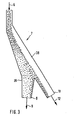
- a coarse grain separator 7 This is, as described in more detail with reference to FIG. 3, formed.
- it contains a thermally resilient sieve with a mesh size of, for example, 12 mm, through which iron sponge particles with a size of more than 12 mm are retained.
- the sponge iron particles of the fine grain fraction leave the coarse grain separator 7 via a first outlet opening 8 and pass through a pipe 9 into a discharge device 10 which contains, for example, a scraper or a screw.
- the iron sponge particles of the coarse grain fraction leave the coarse grain separator 7 through a second outlet opening 11 and reach a cooling unit 13 via a pipe 12, in which they are cooled down to room temperature so that they can be transported to the place where they are processed without a great risk of reoxidation should be.
- the exit of the cooled sponge iron particles from the cooling unit 13 is denoted by 14.
- the discharge device 10 has an outlet opening 16 for the iron sponge particles at the lower end; which at least one down pipe 17 is connected to the interior of the melter gasifier 1.
- the sponge iron particles are dispensed in a metered manner via the outlet opening 16.
- the feed materials required for the melter gasifier are added continuously or intermittently in the amount required for the melter process via the downpipe 17.
- the amount of coal required to form and maintain the coal fluidized bed is added directly to the melter gasifier via a pipe 15.
- the melter gas can be divided into three sections in the operating state, namely a lower section 18, in which pig iron and slag are located, a middle section 19 for the coal fluidized bed and an expanded section upper section 20, which serves as a calming room.
- the sponge iron particles are not supplied at the upper limit of the calming space, but within the calming space near the upper limit of the coal fluidized bed 19. In the present case, this is done by immersing the downpipe 17 deeply into the calming space 20.
- the amount of fine grain discharged with the gas from the melter gasifier which plays a special role in the process according to the invention in relation to the total amount of sponge iron brought into the melter gasifier, can be greatly reduced.
- the cheapest immersion depth of the downpipe 17 can be easily determined experimentally.
- the downpipe expediently ends just above the upper limit of the coal fluidized bed.
- one or more downpipes 17 also makes it possible, by deflecting these pipes at the lower end, by attaching baffle plates, to substantially reduce the vertical speed component of the falling material and thus to increase the residence time of the sponge iron particles in the carbon fluid bed. Because of the high thermal stress of a down pipe immersed in the interior of the melter gasifier, it is advisable to cool the pipe. One way of forming such a down pipe is described with reference to FIG. 2.
- the channels 21 and 222 for tapping the pig iron and the slag are still in the melter gasifier 1 and a nozzle 23 for blowing in an oxygen-containing gas are indicated schematically.
- the reducing gas generated in the melter gasifier 1 leaves the melter gasifier via the outlet 24 at a temperature of approximately 1200 ° C. From here it is forwarded via the reducing gas line 25 to the gas inlet 4 of the direct reduction unit 2. Since the reducing gas introduced into the direct reduction unit 2 must not exceed a temperature of 900 ° C., the hot reducing gas stream rising in the line 25 is added to the cooling gas at the point 26 for cooling control, which is supplied via the line 27. This cooling gas is recirculated blast furnace gas from the direct reduction unit 2 after it has been washed and cooled in a blast furnace gas scrubber 28 and the CO 2 content has been reduced in a CO 2 absorption tower 29.
- the blast furnace gas prepared in this way could already be mixed with the hot reducing gas from the melter gasifier for temperature control, in the exemplary embodiment described it was passed over the cooler 13 and, in the direct heat exchange with the iron sponge particles of the coarse grain fraction, causes these iron sponge particles to cool down.
- the processed top gas heats up to approx. 500 ° C. It is then mixed via line 27 at point 26 into the hot reducing gas stream of line 25 in order to lower its temperature to a value below 900 ° C. If more iron sponge than pig iron is to be produced in the system, it is necessary to preheat a portion of the processed blast furnace gas in the separate recuperator 31 in parallel with the cooling unit 13 in order to be able to set the desired bus gas temperature.
- the unprocessed top gas behind the top gas scrubber 28, the amount of which depends on the heat requirement, is to be used as the heating gas. This also prevents the circulation gas from being enriched with inactive components such as N 2 .
- 30 denotes a compressor upstream of the CO 2 absorption tower 29, which generates the required pressure.
- it is necessary to desulfurize the gas from the melter gasifier 1 in the hot gas desulfurization unit 32.
- some cold gas can be added to this gas to adjust its temperature to the desulfurization process.
- Fig. 2 the part of a down pipe 17 immersed in the melter gasifier is shown in section. Because of the high thermal stress inside the melter gasifier, the downpipe is provided with liquid cooling.
- a liquid channel is formed by three metal tubes 31, 32 and 33 arranged concentrically to one another, through which a cooling liquid, for example water, is passed.
- the cooling system is covered on all sides with a refractory layer 34.
- the downpipe 17 shown contains measures by deflection to reduce the vertical speed of the falling sponge iron particles and thus to increase the dwell time here because of the reduced entry speed into the coal fluidized bed.
- projections 35 arranged in a cascade are provided, on which material can deposit, which thereby serves as wear protection.
- a baffle plate 36 preferably in the form of a blunt cone similar to a Chinese hat, can also be provided at the lower outlet opening of the tube.
- the falling sponge iron particles are deflected and braked in a meandering manner by the projections 35 in the tube and deflected approximately in a horizontal direction by the baffle plate 36, as a result of which their vertical speed component is considerably reduced.
- the ceiling of the melter gasifier is designated by 37 in FIG.
- the coarse grain separator 7 shown schematically in FIG. 3 is designed in the form of an inclined chute 38 with at least one connecting piece 39 branching off from it.
- the tube through which the sponge iron particles discharged from the direct reduction shaft furnace are fed is designated by 6
- the first outlet opening for the fine-grain fraction is 8
- the second outlet opening for the coarse-grain fraction is 11.
- the bulk material entering the coarse grain separator 7 from above is naturally separated during the movement by the coarse grain separator, ie the fine particles settle down and the coarse particles collect on the top.
- the flow profile shown schematically in FIG. 3 is obtained, ie the coarse sponge iron particles are essentially forwarded via the downpipe 38 to the second outlet opening 12 and removed from there.
- the removal of the fine iron sponge particles is controlled according to FIG. 1 by a discharge device 10, which is connected to the G robkornabscheider 7 is connected, then, as desired, the flow resistance for gas rising from the melter gas can be kept relatively high.
- a direct reduction unit designed as a direct reduction shaft furnace 2 has at the top an inlet device 3 for the lumpy iron ore and a gas outlet 5 for the used reducing gas (blast furnace gas) and fuses, a controllable discharge device 41 for the direct reduction of iron sponge particles obtained from the iron ore and a gas inlet 4 for hot reducing.
- the melter gasifier 1 essentially corresponds to the melter gasifier of the first embodiment.
- the ceiling of the upper section 20 serving as a calming space here has a chamber called a carburetor head 42, which is in communication with the calming space.
- a gas outlet 43 for the reducing gas (raw gas) generated in the melter gasifier is provided in the gasifier head.
- a gas inlet 44 for washed and processed top gas from the direct reduction shaft furnace is provided in the gasifier head.
- an inlet 45 for a desulfurizing agent is provided in the gasifier head.
- outlets 21 for molten pig iron and 22 for molten slag In the lower area of the melting gasifier there are outlets 21 for molten pig iron and 22 for molten slag, furthermore at least one nozzle 23 or at least one burner 23a for blowing in above the slag level of gases and fine-grained solids.
- the cooling unit 13a for the hot sponge iron particles discharged by the discharge device 41 there is a cooling unit 13a for the hot sponge iron particles discharged by the discharge device 41.
- the inlet opening 46 of the cooling unit 13a for the hot sponge iron particles is connected to the discharge device 41 through the downpipe 6.
- the down pipe 6 is assigned a level measuring device 47, by means of which the discharge device 41 can be controlled.
- the cooling unit 13a has an outlet 48 for the cooling gas in the upper region next to the inlet opening 46 for the hot sponge iron particles and an inlet 49 for the cooling gas in the lower region next to an outlet opening 14 for the cooled sponge iron particles.
- cooling takes place in countercurrent and in direct exchange with the iron sponge particles sinking in the cooling unit. Since not only the coarse-grain fraction of the sponge iron particles is fed to the cooling unit 13a, as in the exemplary embodiment according to FIG. 1, it is expedient to provide the cooling unit in the upper region with a calming space in order to keep the discharge of fine particles as low as possible. This can be done, for example, by inserting the downpipe 6 into the cooling unit in a certain length, so that a calming space is formed above the pouring cone within the cooling unit.
- a classifying device 7a designed as a sieving station, by means of which the sponge iron is separated particles into a fine grain fraction and a coarse grain fraction.
- the outlet opening 8 for the fine grain fraction is connected by the pipeline 9 to the fine grain container 10 arranged above the melter gasifier, the outlet opening 16 of which is connected to the dip tube 17.
- the separation takes place in the classifying device 7a in such a way that the fine-grain fraction contains only parts with a grain size of up to 3 mm, then it may be expedient to blow at least part of this fraction into the melter gasifier via the nozzles 23 and 23a. Appropriate pipelines to the nozzles must then be provided.
- a pipe 12 is connected to the outlet opening 11 of the classifying device 7a for the coarse grain fraction, which is excreted from the process, through which the coarse grain fraction can be fed to a separate melting unit or a device for compacting, passivating or also a further cooling unit 13 according to FIG. 1 , to which the processed blast furnace gas is fed as a cooling medium.
- a top gas scrubber 28 to the Gichtgasauslledge 5 of the Schwarzreduk- t is ionsschachtofens connected in the embodiment of FIG. 1, and the gas outlet 51 of the G layer scrubber 28 communicates through pipes 52 and 53 with a C0 2 -removing tower 29 in connection, the gas outlet 54 via lines 55 and 56 to inlet 49 of the cooling unit 13a for the cooling gas is connected.
- a pipeline 27 is provided from the gas outlet 48 of the cooling unit 13a to the reducing gas line 25 in order to admix the blast furnace gas which has been processed and heated in the cooling unit 13a with the reducing gas stream which is conducted via this line to the gas inlet 4 of the direct reduction shaft furnace 2.
- the cooling unit 13a is associated with a cooling gas circuit 57 containing the pipeline 56 with a cooling gas scrubber 58 and a compressor 30a. This takes into account the fact that a larger amount of cooling gas is required for cooling in the cooling unit than processed top gas supplied via the pipeline 55 is available.
- a pipeline 59 branches off to the inlet 44 in the carburetor head 42, into which a connecting line 60 to the gas outlet 54 of the C0 2 absorption tower 29 opens.
- Treated top gas of different temperature can be supplied to the gasifier head 42 via the pipeline 59, so that the temperature here is optimized for hot gas desulfurization male temperature is adjustable.
- the outlet 43 in the gasifier head 42 for the reducing gas generated in the melter gasifier 1 is connected via a pipeline 61 to a cyclone 62, to the gas outlet 63 of which the reducing gas line 25 leading to the direct reduction unit is connected.
- a pipeline 61 to a cyclone 62
- the outlet opening 64 for the separated solids is connected by a pipeline 65 to a pipeline 66 which is connected via a compressor 30 to the gas outlet 51 of the top gas scrubber 28.
- the pipeline 66 feeds part of the top gas leaving the top gas scrubber 28 to the burner 23a as an oxygen-containing gas, this gas also serving as a carrier gas for the separated solids of the cyclone 62.
- Oxygen can also be supplied to the burner 23a or the nozzles 23 via a pipeline 67.
- a branch line 68 leads from the pipeline 52 connected to the gas outlet 51 of the top gas scrubber 28 to a steam generator 69.
- a part of the untreated top gas can thus be used as heating gas for the generation of steam which is required in the C0 2 absorption tower 29.
- the process carried out with the system according to FIG. 4 also takes into account the requirement in a particularly economical manner the sulfur content of the pig iron melted in the melter gasifier and in that which has been eliminated from the method
- measures are provided to reduce the amount of energy required for melting the fine grain fraction in the melter gasifier and the blast furnace gas of the direct reduction unit partly in the unprocessed state, partly after a C0 2 wash and after direct heat exchange in the cooling unit for the iron sponge particles discharged from the direct reduction unit to feed the process.
- the proportion of energy required for the heat of fusion, which is to be applied by burning coal, is reduced by the fact that, when the sponge iron particles are separated in the classifying device 7a, the proportion of the fine-grain fraction is reduced compared to the coarse-grain fraction, ie the particle size of the fine-grain fraction fed to the melter gasifier 1 is up to a size of 5 mm, preferably 3 mm, is reduced. Because of the longer residence time in the fluidized bed of the melter gasifier, these particles can be melted with a significantly lower energy expenditure, that is to say with less coal and thus less sulfur. It is then also possible to use a portion of the unprocessed top gas supplied by the top gas scrubber 28, which contains carbon dioxide and water vapor, for gasifying the coal.
- the over the The amount of blast gas supplied to pipeline 66 should be set so that the carburetor head temperature in connection with other temperature control measures is between 850 ° and 1250 ° C., preferably 1100 ° C. Due to the possible use of blast furnace gas as an oxygen carrier for carrying out the gasification oxygen consumption can, of course p ro ton of product Degrading and thus increase the efficiency of the process.
- a further saving in coal and thus a further reduction in the sulfur content in the reducing gas and in the sponge iron can be achieved in that blast furnace gas processed in the CO 2 absorption tower is mixed with the reducing gas.
- This is done in the process with the system according to FIG. 4 in that part of the blast furnace gas processed in the C0 2 absorption tower 29 is passed through the cooling unit 13a via the pipes 55 and 56, and this part is heated in direct contact with the hot sponge iron particles and then again a part thereof is fed to the reducing gas line 25 and a further part to the carburetor head 42 via the pipeline 59.
- the other part of the processed top gas supplied by the CO 2 absorption tower is fed directly to the gasifier head 42 via the pipe 60 and part of the pipe 59.
- the amount of processed blast furnace gas mixed with the reducing gas can reduce the consumption of coal and oxygen, and thus the amount of sulfur introduced with coal, and the sulfur content in the reducing gas to about half.
- the measures mentioned allow the sulfur content of the iron sponge particles to be reduced so much even when using sulfur-rich coal that the coarse-grain fraction which has been separated out can be processed in a steel mill without further measures for sulfur removal.
- the fine grain fraction which for the reasons mentioned has a significantly higher sulfur content than the coarse grain fraction - due to the larger surface in relation to the weight, a larger amount of sulfur is bound by the fine sponge iron particles - is desulfurized and bound at least in part by the desulfurization agent supplied to the melter gasifier the desulfurizing agent is excreted through the slag.
Landscapes
- Engineering & Computer Science (AREA)
- Chemical & Material Sciences (AREA)
- Manufacturing & Machinery (AREA)
- Materials Engineering (AREA)
- Metallurgy (AREA)
- Organic Chemistry (AREA)
- Manufacture Of Iron (AREA)
- Manufacture Of Metal Powder And Suspensions Thereof (AREA)
- Medicines Containing Material From Animals Or Micro-Organisms (AREA)
- Manufacture And Refinement Of Metals (AREA)
- Waste-Gas Treatment And Other Accessory Devices For Furnaces (AREA)
- Battery Electrode And Active Subsutance (AREA)
Abstract
Description
Die Erfindung betrifft ein Verfahren gemäß dem Gattungsbegriff des Patentanspruchs 1. Ferner bezieht sie sich auf eine Anlage gemäß dem Gattungsbegriff der Patentansprüche 25, 32 und 33. Unter dem Begriff stückiges Eisenerz soll Eisenerz in beliebiger stückiger Form, also auch in Form von Pellets verstanden werden.The invention relates to a method according to the preamble of claim 1. Furthermore, it relates to a system according to the preamble of
Ein Verfahren und eine Anlage dieser Art sind durch die DE-C2-30 34 539 bekannt geworden. Bei dem bekannten Verfahren entsteht beim Einschmelzen des Eisenschwamms ca. 40% mehr Reduktionsgas,als für die Erzeugung der gleichen Eisenschwamm-Menge erforderlich ist. Für einen wirtschaftlichen Betrieb der Anlage ist es erforderlich, daß Abnehmer für das überschüssige Gas vorhanden sind. Dies hat zur Folge, daß eine Koppelung mit anderen Anlagen erfolgen muß. Jede Koppelung von mehreren Anlagen führt jedoch zu einer Verringerung der Verfügbarkeit der Gesamtanlage und damit zu einer Verschlechterung der Wirtschaftlichkeit.A method and a plant of this type are known from DE-C2-30 34 539. In the known method, about 40% more reducing gas is produced when the sponge iron melts than is required to produce the same amount of sponge iron. For the plant to operate economically, it is necessary to have customers for the excess gas. As a result, it must be coupled to other systems. However, each coupling of several systems leads to a reduction in the availability of the overall system and thus to a deterioration in economy.
Je nach verwendetem Eisenerz werden aus dem Reduktionsaggregat auch größere Eisenschwammstücke ausgetragen, die das Kohlefließbett im Einschmelzvergaser schnell durchwandern, da sie schon mit großer Geschwindigkeit in den Beruhigungsraum eintreten, in dem sich ihre Fallgeschwindig-' keit weiter erhöht. Aufgrund der kurzen Verweilzeit im Kohlefließbett ist ihre Erwärmung entsprechend geringer.Depending on the iron ore used, larger pieces of iron sponge are discharged from the reduction unit, which quickly move through the coal fluidized bed in the melter gasifier, since they enter the calming room at high speed, in which their falling speed increases further. Due to the short dwell time in the coal fluidized bed, their heating is correspondingly less.
Kleine Eisenschwammpartikel verweilen dagegen im Fließbett länger, erwärmen sich auf eine höhere Temperatur und werden schneller aufgeschmolzen.Small iron sponge particles, on the other hand, stay longer in the fluidized bed, warm up to a higher temperature and are melted faster.
Aufgabe der Erfindung ist es, ein Verfahren der einleitend genannten Art verfügbar zu machen, das ohne Gasüberschuß wirtschaftlich arbeitet und mit dem die spezifische Leistung des Einschmelzvergasers erhöht und dessen Arbeitsweise verbessert werden kann. Ferner ist es Aufgabe dieser Erfindung, eine Anlage zur Durchführung dieses Verfahrens verfügbar zu machen.The object of the invention is to make available a method of the type mentioned in the introduction, which works economically without excess gas and with which the specific performance of the melter gasifier can be increased and its mode of operation can be improved. Furthermore, it is an object of this invention to make a system available for carrying out this method.
Das erfindungsgemäße Verfahren ist durch die Merkmale des Anspruchs 1 gekennzeichnet. Vorteilhafte Ausgestaltungen dieses Verfahrens sind den Ansprüchen 2 bis 24 zu entnehmen. Die erfindungsgemäße Anlage ist durch die Merkmale des Anspruchs 25 gekennzeichnet. Vorteilhafte Ausgestaltungen der erfindungsgemäßen Vorrichtung sind in den Ansprüchen 26 bis 36 beschrieben.The method according to the invention is characterized by the features of claim 1. Advantageous embodiments of this method can be found in
Beim erfindungsgemäßen Verfahren wird dem Einschmelzvergaser nicht die gesamte Menge der im Direktreduktionsaggregat erzeugten Eisenschwammpartikel zugeführt, sondern nur ein Teil, so daß beim Einschmelzen dieser Teilmenge auch weniger Gas anfällt und auf diese Weise ein Überschuß an Reduktionsgas vermieden werden kann. Die dem Einschmelzvergaser zugeführte Teilmenge an Eisenschwammpartikeln ist insoferne ausgewählt, als die Partikelgröße nach oben begrenzt ist. Hierdurch wird vermieden, daß größere Eisenschwammstücke ohne ausreichende Erwärmung das Kohlefließbett durchwandern und es dann in der Schmelzzone des Einschmelzvergasers zu einer Anhäufung von nur mit erhöhtem Energieaufwand aufschmelzbarem Material kommt. Die auf dem Weg vom Reduktionsaggregat zum Einschmelzvergaser ausgeschiedene Grobkornfraktion kann entweder im heißen Zustand einem weiteren Einschmelzgefäß, wie einem Lichtbogenofen, zugeführt werden, sie kann aber auch heißbrikettiert, passiviert oder gekühlt werden, um als Einsatzmaterial für einen Schmelzofen zur Verfügung zu stehen.In the process according to the invention, the entire amount of the sponge iron particles produced in the direct reduction unit is not supplied to the melter gasifier, but only a part, so that less gas is produced when this partial amount is melted, and an excess of reducing gas can be avoided in this way. The partial quantity of sponge iron particles supplied to the melter gasifier is selected insofar as the upper limit of the particle size is limited. This avoids that larger pieces of iron sponge migrate through the coal fluidized bed without sufficient heating and then there is a build-up of material which can only be melted with increased energy expenditure in the melting zone of the melter gasifier. The coarse-grain fraction separated on the way from the reduction unit to the melter gasifier can either be fed to another meltdown vessel, such as an electric arc furnace, when hot, but it can also be hot-briquetted, passivated or cooled in order to be used as a feedstock for one Melting furnace to be available.
Da bei dem erfindungsgemäßen Verfahren nur die Feinkornfraktion im Einschmelzvergaser eingeschmolzen wird, können Schwierigkeiten entstehen, falls im Einschmelzvergaser unveredelte, schwefelreiche Kohle eingesetzt wird. Die Feinkornfraktion bindet nämlich wegen der auf das Gewicht bezogenen größeren Oberfläche der feinen Eisenschwammpartikel einen größeren Anteil des im Reduktionsgas enthaltenen Schwefels als die Grobkornfraktion, so daß es bei dem im Einschmelzvergaser erzeugten flüssigen Roheisen zu einem unerwünscht hohen Anstieg des Schwefelgehalts kommt. Es sind dann zusätzliche Maßnahmen zur Verringerung des Schwefelgehaltes erforderlich, die integriert in das erfindungsgemäße Verfahren einzeln oder in Kombination in den folgenden Schritten bestehen können:
- 1. Dem Einschmelzvergaser wird ein Entschwefelungsmittel zugeführt.
- 2. Der Anteil des durch Vergasung von Kohle erzeugten Rohgases im Reduktionsgas wird durch Beimischen eines Teils des Gichtgases des Direktreduktionsaggregates nach einer C02-Wäsche verringert; und
- 3. der Anteil der Feinkornfraktion, die im Einschmelzvergaser eingeschmolzen wird, wird zur Einsparung an erforderlicher Schmelzwärme, die wiederum durch Verbrennung von Kohle aufgebracht werden muß, verringert.
- 1. A desulfurizing agent is fed to the melter gasifier.
- 2. The proportion of the raw gas generated by gasification of coal in the reducing gas is reduced by admixing part of the blast furnace gas of the direct reduction unit after a CO 2 wash; and
- 3. The proportion of the fine grain fraction which is melted down in the melter gasifier is reduced in order to save the required heat of fusion, which in turn has to be applied by burning coal.
Bei der unter 3. genannten Maßnahme ist es auch möglich, dem Einschmelzvergaser einen Teil des Gichtgases des Direktreduktionsaggregates als Sauerstoffträger zuzuführen und durch endotherme Reaktionen mit dem Kohlendioxid und dem Wasserdampf im Gichtgas einen Teil der Kohle zu vergasen.With the measure mentioned under 3, it is also possible to supply the melter gasifier with part of the blast furnace gas of the direct reduction unit as an oxygen carrier and through endothermic reactions with the carbon dioxide and to gasify part of the coal in the steam in the blast furnace gas.
Durch die Herabsetzung des Schwefelgehalts der Eisenschwammpartikel der Feinkornfraktion wird bei den genannten Maßnahmen auch eine wesentliche Herabsetzung des Schwefelgehaltes der Eisenschwammpartikel der Grobkornfraktion, die anderweitig verwertet werden, erreicht, so daß beim Einschmelzen dieser Eisenschwammpartikel keine besonderen Maßnahmen zur Schwefelentfernung mehr vorgesehen werden müssen.By reducing the sulfur content of the sponge iron particles of the fine-grain fraction, a significant reduction in the sulfur content of the sponge iron particles of the coarse-grain fraction, which are otherwise used, is achieved with the measures mentioned, so that no special sulfur removal measures need to be provided when these sponge iron particles are melted down.
Wird die Trennung der Eisenschwammpartikel in eine Feinkorn- und in eine Grobkornfraktion unmittelbar nach dem Austrag aus dem Direktreduktionsaggregat vorgenommen, dann muß der Grobkornabscheider für Temperaturen zwischen 700°und 900°C ausgelegt sein, da die Eisenschwammpartikel das Direktreduktionsaggregat mit diesen Temperaturen verlassen. Bei einigen Klassiervorrichtungen, insbesondere bei der Verwendung von Sieben, kann dies zu Schwierigkeiten führen. In diesem Fall ist es zweckmäßig, die Klassierung der Eisenschwammpartikel erst nach einer Abkühlung vorzunehmen, wobei vorzugsweise gewaschenes und aufbereitetes Gichtgas des Direktreduktionsaggregates als Kühlmedium verwendet wird. In diesem Fall ist es zweckmäßig, Maßnahmen vorzusehen,durch die dem Kühlmedium der Weg über die Förderleitung der Eisenschwammpartikel in das Direktreduktionsaggregat versperrt bleibt.If the separation of the sponge iron particles into a fine grain and a coarse grain fraction is carried out immediately after the discharge from the direct reduction unit, the coarse grain separator must be designed for temperatures between 700 ° and 900 ° C, since the iron sponge particles leave the direct reduction unit at these temperatures. With some classifiers, especially when using screens, this can cause difficulties. In this case, it is expedient to carry out the classification of the sponge iron particles only after cooling, preferably using washed and processed top gas from the direct reduction unit as the cooling medium. In this case, it is expedient to provide measures by which the path of the cooling medium via the delivery line of the sponge iron particles into the direct reduction unit remains blocked.
Eine Kühlung der ausgeschiedenen Eisenschwammpartikel erfolgt vorzugsweise durch abgekühltes, gereinigtes und aufbereitetes Gichtgas aus dem Reduktionsaggregat, das nach dem Wärmetausch mit den Eisenschwammpartikeln dem vom Einschmelzvergaser zum Reduktionsaggregat geleiteten heißen Reduktionsgasstrom zur Temperatursteuerung beigemischt wird. Auf diese Weise wird auch das Gichtgas des Reduktionsaggregates wirtschaftlich ausgenutzt.The separated sponge iron particles are preferably cooled by cooled, cleaned and treated top gas from the reduction unit, which, after the heat exchange with the sponge iron particles, is passed to the reduction unit from the melter gasifier hot reducing gas stream is added for temperature control. In this way, the top gas of the reduction unit is also used economically.
Durch die Ausscheidung der Eisenschwammpartikel der Grobkornfraktion wird der relative Anteil an Feinmaterial des dem Einschmelzvergaser zugeführten Eisenschwammes erhöht und damit auch die Menge eines möglichen Austrags an Feinmaterial aus dem Einschmelzvergaser. Gemäß einer Weiterbildung der Erfindung wird deshalb die Stelle, an der die Eisenschwammpartikel innerhalb des Einschmelzvergasers freigegeben werden, vom Deckel des Gefäßes nach unten in die Nähe der Obergrenze des Kohlefließbettes verlegt. Dies geschieht vorzugsweise durch ein Fallrohr, das von oben in den Innenraum des Einschmelzvergasers bis in die Nähe der Obergrenze des sich in dem Einschmelzvergaser ausbildenden Kohlefließbettes eintaucht. Auf diese Weise ist es auch möglich, die Eisenschwammpartikel mit abgebremster Vertikalgeschwindigkeitskomponente zuzuführen, sei es durch eine entsprechende Umlenkung mittels kaskadenförmig angeordneter Vorsprünge im unteren Bereich des Fallrohres oder durch wenigstens ein Prallblech unterhalb des Fallrohres, das vorzugsweise in Form eines stumpfen Kegels ähnlich einem Chinesenhut ausgebildet ist.The separation of the sponge iron particles of the coarse grain fraction increases the relative proportion of fine material of the sponge iron fed to the melter and thus also the amount of possible discharge of fine material from the melter. According to a further development of the invention, the point at which the sponge iron particles are released within the melter gasifier is therefore moved down from the lid of the vessel to the vicinity of the upper limit of the coal fluidized bed. This is preferably done through a downpipe which dips from above into the interior of the melter gasifier up to the vicinity of the upper limit of the coal fluidized bed formed in the melter gasifier. In this way, it is also possible to supply the sponge iron particles with the braked vertical speed component, either by a corresponding deflection by means of projections arranged in a cascade in the lower region of the downpipe or by at least one baffle plate below the downpipe, which is preferably in the form of a blunt cone similar to a Chinese hat is.
Für eine dosierte Zufuhr der Eisenschwammpartikel in den Einschmelzvergaser ist es zweckmäßig zwischen dem Grobkornabscheider und dem Einschmelzvergaser eine Austragvorrichtung vorzusehen, durch die das Fallrohr oder die Fallrohre in gesteuerter Menge mit Eisenschwammpartikeln beliefert werden. Auf diese Weise läßt sich auch der Strömungswiderstand für das über das Fallrohr hochsteigende Reduktionsgas erhöhen und eine Überhitzung und Sinterung der Eisenschwammpartikel im Bereich des Grobkornabscheiders und im unteren Teil des Reduktionsaggregates vermeiden.For a metered supply of the sponge iron particles into the melting gasifier, it is expedient to provide a discharge device between the coarse grain separator and the melting gasifier, through which the downpipe or the downpipes are supplied in a controlled amount with sponge iron particles. In this way, the flow resistance for the reducing gas rising via the downpipe can also be increased and overheating and sintering of the sponge iron particles in the area of the coarse grain separator and in the lower part of the reduction unit can be avoided.
Die Erfindung wird durch zwei Ausführungsbeispiele anhand von vier Figuren näher erläutert. Es zeigen:
- Fig. 1 eine schematische Darstellung einer ersten Ausführungsform eines Verfahrens und einer Anlage gemäß dieser Erfindung,
- Fig. 2 in einem Längsschnitt die Ausbildung eines Fallrohres mit Flüssigkeitskühlung,
- Fig. 3 die schematische Darstellung eines Grobkornabscheiders, und
- Fig. 4 eine schematische Darstellung einer zweiten Ausführungsform eines Verfahrens und einer Anlage gemäß dieser Erfindung.
- 1 is a schematic representation of a first embodiment of a method and a plant according to this invention,
- 2 in a longitudinal section the formation of a downpipe with liquid cooling,
- Fig. 3 is a schematic representation of a coarse grain separator, and
- Fig. 4 is a schematic representation of a second embodiment of a method and a plant according to this invention.
Die in Fig. 1 schematisch dargestellte Anlage zur direkten Erzeugung von flüssigem Roheisen aus stückigem Eisenerz enthält einen Einschmelzvergaser 1 der in der EP-B1-0 010 627 beschriebenen Art. Oberhalb des Einschmelzvergasers ist ein Schachtofen 2 angeordnet, der entsprechend seiner Funktionsweise mit dem oberen Teil eines Hochofens oder eines Direktreduktionsschachtofens verglichen werden kann. Letzterer ist im Prinzip beispielsweise in der DE-A-29 35 707 beschrieben. Dem Direktreduktionsschachtofen wird von oben stückiges Eisenerz zugeführt - durch einen Pfeil 3 angedeutet -, das in Form einer losen Schüttung im Schachtofen absinkt und mittels eines über einen mittleren Gaseinlaß 4 eingeblasenen heißen Reduktionsgases einer Temperatur von etwa 750° bis 900°C zu Eisenschwamm reduziert wird. Das verbrauchte Reduktionsgas, im folgenden Gichtgas genannt, verläßt den Schachtofen 2 über einen oberen Gasauslaß 5.The plant for the direct production of molten pig iron from lumpy iron ore, shown schematically in FIG. 1, contains a melter gasifier 1 of the type described in EP-B1-0 010 627. Above the melter gasifier, a
Der durch Reduktion des stückigen Eisenerzes erzeugte heiße Eisenschwamm wird mit einer Temperatur von etwa 750° bis 850°C unten aus dem Direktreduktionsschachtofen 2 ausgetragen und gelangt über ein Rohr 6 in einen Grobkornabscheider 7. Dieser ist, wie anhand von Fig. 3 näher beschrieben, ausgebildet. Alternativ enthält er ein thermisch belastbares Sieb einer Maschenweite von z.B. 12 mm, durch das Eisenschwammpartikel mit einer Größe von mehr als 12 mm zurückgehalten werden. Es erfolgt eine Trennung in eine Feinkornfraktion und eine Grobkornfraktion. Die Eisenschwammpartikel der Feinkornfraktion verlassen den Grobkornabscheider 7 über eine erste Austrittsöffnung 8 und gelangen über ein Rohr 9 in eine Austragvorrichtung 10, die beispielsweise einen Räumer oder eine Schnecke enthält. Die Eisenschwammpartikel der Grobkornfraktion verlassen den Grobkornabscheider 7 durch eine zweite Austrittsöffnung 11 und gelangen über ein Rohr 12 zu einem Kühlaggregat 13, in dem sie bis auf Raumtemperatur herabgekühlt werden, so daß sie ohne große Reoxidationsgefahr an die Stelle weitertransportiert werden können, an der sie verarbeitet werden sollen. Der Austritt der gekühlten Eisenschwammpartikel aus dem Kühlaggregat 13 ist mit 14 bezeichnet.The hot sponge iron produced by reducing the lumpy iron ore is removed from the direct
Die Austragvorrichtung 10 weist am unteren Ende eine Austrittsöffnung 16 für die Eisenschwammpartikel auf; die überwenigstens ein Fallrohr 17 mit dem Innenraum des Einschmelzvergasers 1 in Verbindung steht. Die Eisenschwammpartikel werden über die Austrittsöffnung 16 dosiert abgegeben. Auf diese Weise werden die für den Einschmelzvergaser erforderlichen Einsatzmaterialien kontinuierlich oder intermittierend in der für den Einschmelzprozeß erforderliche Menge über das Fallrohr 17 zugegeben. Die zur Bildung und Aufrechterhaltung des Kohlefließbettes erforderliche Kohlemenge wird dem Einschmelzvergaser über ein Rohr 15 direkt zugegeben.The
Wie in oder EP-B1-0 010 627 beschrieben, kann der Einschmelzwergaser im Betriebszuständ in drei Abschnitte unterteilt werden, nämlich in einen unteren Abschnitt 18, in dem sich Roheisen und Schlacke befinden, in einen mittleren Abschnitt 19 für das Kohlefließbett und in einen erweiterten oberen Abschnitt 20, der als Beruhigungsraum dieent. Gemäß einer Weiterbildung der Erfindung erfolgt die Zufuhr der Eisenschwammpartikel nicht an der Obergrernze des Beruhigungsraumes, sondern innerhalb des Beruhigungsraumes in der Nähe der Obergrenze des Kohlefließbetttes 19. Dies geschieht im vorliegenden Fall dadurch, daß das Fallrohr 17 tief in den Beruhigungsraum 20 eintaucrht. Auf diese Weise läßt sich die mit dem Gas aus dem Einschmelzvergaser ausgetragene Feinkornmenge, die bei dem erfindungsgemäßen Verfahren bezogen auf die Gesamtmeenge an in den Einschmelzvergaser gebrachtem Eisenschwamm eine besondere Rolle spielt, stark reduzieren. Die günstigste Eintauchtiefe des Fallrohres 17 läßt sich experimeentell einfach bestimmen. Zweckmäßig endet das Fallrohrr kurz oberhalb der Obergrenze des Kohlefließbettes.As described in or EP-B1-0 010 627, the melter gas can be divided into three sections in the operating state, namely a
Die Verwendung eines oder mehrerer Fallrohre 17 ermöglicht zudem, ssei es durch Umlenkung dieser Rohre am unteren Ende, seei es durch Anbringen von Prallblechen, die senkrechte Geschwindigkeitskomponente des herabfallenden Gutes weesentlich zu vermindern und damit die Verweilzeit der Eiseenschwammpartikel im Kohlefließbett zu vergrößern. Wegen deer hohen thermischen Beanspruchung eines in den Innenraum des Einschmelzvergasers eintauchenden Fallrohres ist es zzweckmäßig, das Rohr zu kühlen. Eine Möglichkeit der Ausbildung eines solchen Fallrohres wird anhand von Fig. 2 beschrieben.The use of one or
In Fig. 1 sind bei dem Einschmelzvergaser 1 noch die Rinnen 21 und 222 für den Abstich des Roheisens und der Schlacke sowie eine Düse 23 zum Einblasen eines sauerstoffhaltigen Gases schematisch angedeutet.In FIG. 1, the
Das im Einschmelzvergaser 1 erzeugte Reduktionsgas verläßt den Einschmelzvergaser über den Auslaß 24 mit einer Temperatur von etwa 1200°C. Es wird von hier über die Reduktionsgasleitung 25 zum Gaseinlaß 4 des Direktreduktionsaggregates 2 weitergeleitet. Da das in das Direktreduktionsaggregat 2 eingeleitete Reduktionsgas eine Temperatur von 900°C nicht überschreiten darf, wird den in der Leitung 25 aufsteigenden heißen Reduktionsgasstrom zur Temperatursteuerung an der Stelle 26 Kühlgas beigemischt, das über die Leitung 27 herangeführt wird. Dieses Kühlgas ist zurückgeführtes Gichtgas des Direktreduktionsaggregates 2, nachdem dieses in einem Gichtgaswäscher 28 gewaschen und gekühlt worden ist und in einem C02- Absorptionsturm 29 der C02- Anteil verringert worden ist. Obwohl das so aufbereitete Gichtgas bereits in dieser Form dem heißen Reduktionsgas aus dem Einschmelzvergaser zur Temperatursteuerung beigemischt werden könnte, wurde es bei dem beschriebenen Ausführungsbeispiel über den Kühler 13 geleitet und bewirkt hier im direkten Wärmeaustausch mit den Eisenschwammpartikeln der Grobkornfraktion eine Abkühlung dieser Eisenschwammpartikel. Bei diesem Wärmeaustausch erwärmt sich das aufbereitete Gichtgas auf ca. 500°C. Es wird dann über die Leitung 27 an der Stelle 26 dem heißen Reduktionsgasstrom der Leitung 25 zugemischt, um dessen Temperatur auf einen Wert unterhalb 9000C zu erniedrigen. Wenn in der Anlage mehr Eisenschwamm als Roheisen erzeugt werden soll, ist es erforderlich, einen Teil des aufbereiteten Gichtgases im separaten Rekuperator 31 in Parallelschaltung zum Kühlaggregat 13 vorzuwärmen, um die gewünschte Bustlegastemperatur einstellen zu können. Als Heizgas soll das unaufbereitete Gichtgas hinter dem Gichtgaswäscher 28 verwendet werden, dessen Menge vom Wärmebedarf abhängig ist. Dadurch wird auch die Anreicherung des Kreislaufgases mit inaktiven Komponenten wie N2 vermieden.The reducing gas generated in the melter gasifier 1 leaves the melter gasifier via the
Mit 30 ist in Fig. 1 ein dem CO2- Absorptionsturm29 vorgeschalteter Verdichter bezeichnet, der den erforderlichen Druck erzeugt. Um Eisenschwamm mit wenig Schwefel erzeugen zu können, ist es erforderlich, das Gas aus dem Einschmelzvergaser 1 im Heißgasentschwefelungsaggregat 32 zu entschwefeln. Zu diesem Zweck kann diesem Gas etwas Kaltgas beigemischt werden, um seine Temperatur dem Entschwefelungsvorgang anzupassen.In FIG. 1, 30 denotes a compressor upstream of the CO 2 absorption tower 29, which generates the required pressure. In order to be able to produce sponge iron with little sulfur, it is necessary to desulfurize the gas from the melter gasifier 1 in the hot
Zur Vermeidung einer Sinterbildung ist es erforderlich, daß die Menge der über die Rohre 17, 9 und 6 nach oben gelangenden heißen Gase aus dem Einschmelzvergaser gering gehalten wird. Dies ist durch einen hohen Strömungswiderstand im Bereich Austragsvorrichtung 10,Fallrohr 9 und Grobkornabscheider 7 möglich, wenn der Austrag so gesteuert wird, daß das Rohr 9 stets wenigstens zum Teil mit Material ausgefüllt ist. Auf diese Weise wird der Widerstand des Nebenweges zur Reduktionsgasleitung 25 so hoch gehalten, daß sich keine schädliche Gasströmung über diesen Nebenweg ausbilden kann.To avoid sintering, it is necessary that the amount of hot gases coming up through the
In Fig. 2 ist der in den Einschmelzvergaser eintauchende Teil eines Fallrohres 17 im Schnitt dargestellt. Wegen der hohen thermischen Beanspruchung im Inneren des Einschmelzvergasers ist das Fallrohr mit einer Flüssigkeitskühlung 'versehen. Zu diesem Zweck wird durch drei konzentrisch zueinander angeordnete Metallrohre 31, 32 und 33 in der dargestellten Weise ein Flüssigkeitskanal gebildet, durch den eine Kühlflüssigkeit beispielsweise Wasser hindurchgeleitet wird. Das Kühlsystem ist allseitig mit einer feuerfesten Schicht 34 bedeckt.In Fig. 2 the part of a
Das dargestellte Fallrohr 17 enthält Maßnahmen durch Umlenkung die Vertikalgeschwindigkeit der herabfallenden Eisenschwammpartikel zu verringern und damit wegen der verringerten Eintrittsgeschwindigkeit in das Kohlefließbett hier die Verweilzeit zu erhöhen. Zu diesem Zweck sind im unteren Bereich des Fallrohres kaskadenförmig angeordnete Vorsprünge 35 vorgesehen, auf denen sich Material ablagern kann, das dadurch als Verschleißschutz dient. Anstelle dieser Vorsprünge oder zusätzlich zu diesen Vorsprüngen kann auch an der unteren Austrittsöffnung des Rohres ein Prallblech 36, vorzugsweise in Form eines stumpfen Kegels ähnlich einem Chinesenhut, vorgesehen sein. Die herabfallenden Eisenschwammpartikel werden durch die Vorsprünge 35 im Rohr mäanderförmig abgelenkt und abgebremst und durch das Prallblech 36 etwa in eine horizontale Richtung abgelenkt, wodurch ihre vertikale Geschwindigkeitskomponente beträchtlich verringert wird. Mit 37 ist in Fig.2 die Decke des Einschmelzvergasers bezeichnet.The
Der in Fig.3 schematisch dargestellte Grobkornabscheider 7 ist in Form einer schrägen Fallrinne 38 mit wenigstens einem von dieser nach unten abzweigenden Stutzen 39 ausgebildet. Entsprechend Fig. 1 ist das Rohr über das die aus dem Direktreduktionsschachtofen ausgetragenen Eisenschwammpartikel zugeführt werden mit 6 bezeichnet, die erste.Austrittsöffnung für die Feinkornfraktion mit 8 und die zweite Austrittsöffnung für die Grobkornfraktion mit 11.The
Das von oben in den Grobkornabscheider 7 eintretende Schüttgut wird während der Bewegung durch den Grobkornabscheider natürlich entmischt, d.h. die feinen Partikel setzen sich nach unten ab und die groben sammeln, sich an der Oberseite. Bei geeigneter Steuerung des Abzugs der Eisenschwammpartikel der Feinkornfraktion aus der ersten Austrittsöffnung 8 erhält man das in Fig. 3 schematisch dargestellte Fließprofil, d.h. die groben Eisenschwammpartikel werden im wesentlichen über das Fallrohr 38 zur zweiten Austrittsöffnung 12 weitergeleitet und von dort abgezogen. Erfolgt die Steuerung des Abzugs der feinen Eisenschwammpartikel entsprechend Fig. 1 durch eine Austragsvorrichtung 10, die über ein Rohr mit dem Grobkornabscheider 7 verbunden ist, dann läßt sich, wie gewünscht, der Strömungswiderstand für daas aus dem Einschmelzvergaser hochsteigende Gas verhälttnismäßig hoch halten.The bulk material entering the
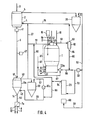
Bei der schematischen Darstellung einer zzweiten Ausführungsform einer Anlage nach Fig. 4 sind die mit der Anlage nach Fig. 1 übereinstimmenden Teile durch dieselben Bezugszeichen gekennzeichnet.In the schematic representation of a second embodiment of a system according to FIG. 4, the parts which correspond to the system according to FIG. 1 are identified by the same reference numerals.
Ein als Direktreduktionsschachtofen 2 ausgebildetes Direktreduktionsaggregat weist oben eine Eintraxgvorrichtung 3 für das stückige Eisenerz und einen Gasauslaß 5 für das verbrauchte Reduktionsgas (Gichtgas) und Lunten eine steuerbare Austragvorrichtung 41 für die durchh Direktreduktion aus dem Eisenerz gewonnenen Eisenschwammpaartikel sowie einen Gaseinlaß 4 für heißes Reduktionsgas auf. Der Einschmelzvergaser 1 entspricht im wesentlichen dem Einschmelzvergaser der ersten Ausführungsform. Die Decke des als Beruhigungsraum dienenden oberen Abschnittes 20 weist hier jedoch eine als Vergaserkopf 42 bezeichnete Kammer auf, die mit dem Beruhigungsraum in Verbindung steht. Im .Vergaserkopf ist ein Gasauslaß 43 für dass im Einschmelzvergaser erzeugte Reduktionsgas(Rohgas), eein Gaseinlaß 44 für gewaschenes und aufbereites Gichtgas des Direktreduktionsschachtofens sowie ein Einlaß 45 für ein Entschwefelungsmittel vorgesehen. Durch die Decke des Einschmelzvergasers sind außerdem das Rohr 155 für die Zugabe von Kohle und das Tauchrohr 17 für die Zugabe der Feinkornfraktion durchgeführt.A direct reduction unit designed as a direct
Im unteren Bereich des Einschmelzvergaserss sind Auslässe 21 für flüssiges Roheisen sowie 22 für flüssige Schlacke, ferner oberhalb des Schlackenspiegels weniigstens eine Düse 23 bzw. wenigstens ein Brenner 23a für das Einblasen von Gasen und feinkörnigen Feststoffen vorgesehen.In the lower area of the melting gasifier there are
Unterhalb des Direktreduktionsschachtofens 2 befindet sich ein Kühlaggregat 13a für die durch die Austragvorrichtung 41 ausgetragenen heißen Eisenschwammpartikel. Die Eintrittsöffnung 46 des Kühlaggregates 13a für die heißen Eisenschwammpartikel steht durch die Fallrohrleitung 6 mit der Austragvorrichtung 41 in Verbindung. Der Fallrohrleitung 6 ist eine Niveaumeßeinrichtung 47 zugeordnet, durch die die Austragvorrichtung 41 steuerbar ist.Below the direct
Das Kühlaggregat 13a weist im oberen Bereich neben der ' Eintrittsöffnung 46 für die heißen Eisenschwammpartikel einen Auslaß 48 für das Kühlgas und im unteren Bereich neben einer Austrittsöffnung 14 für die gekühlten Eisenschwammpartikel einen Einlaß 49 für das Kühlgas auf. Die Kühlung erfolgt wie bei dem Ausführungsbeispiel nach Fig. 1 im Gegenstrom und im direkten Austausch mit den im Kühlaggregat absinkenden Eisenschwammpartikeln. Da dem Kühlaggregat 13a nicht nur, wie bei dem Ausführungsbeispiel nach Fig. 1, die Grobkornfraktion der Eisenschwammpartikel zugeführt wird, ist es zweckmäßig, das Kühlaggregat im oberen Bereich mit einem Beruhigungsraum zu versehen, um den Austrag an Feinteilen möglichst gering zu halten. Dies kann beispielsweise dadurch geschehen, daß das Fallrohr 6 in einer bestimmten Länge in das Kühlaggregat eingeführt wird, so daß sich oberhalb des Schüttkegels innerhalb des Kühlaggregates ein Beruhigungsraum ausbildet.The
Unterhalb des Kühlaggregates und mit dessen Austrittsöffnung 14 durch ein weiteres Fallrohr 48 verbunden, befindet sich eine als Siebstation ausgebildete Klassiervorrichtung 7a, durch die die Trennung der Eisenschwammpartikel in eine Feinkornfraktion und in eine Grobkornfraktion bewirkt wird. Die Austrittsöffnung 8 für die Feinkornfraktion ist durch die Rohrleitung 9 mit dem oberhalb des Einschmelzvergasers angeordneten Feinkornbehälter10 verbunden, dessen Austrittsöffnung 16 mit dem Tauchrohr 17 in Verbindung steht. Alternativ oder zusätzlich kann auch eine Verbindung zu dem Rohr 15 vorhanden sein, über das die Kohle in den Einschmelzvergaser eingeführt wird. Falls die Klassiervorrichtung 7a aus Platzmangel nicht oberhalb des Einschmelzvergasers 1 angeordnet und die Rohrleitung 9 nicht als Fallrohrleitung ausgebildet sein kann, sind in dieser Rohrleitung geeignete Fördermittel für die Feinkornfraktion vorzusehen. Erfolgt die Trennung in der Klassiervorrichtung-7a so, daß die Feinkornfraktion nur Teile mit einer Körnung bis 3 mm enthält, dann kann es zweckmäßig sein, wenigstens einen Teil dieser Fraktion über die Düsen 23 bzw. 23a in den Einschmelzvergaser einzublasen. Es sind dann entsprechende Rohrleitungen zu den Düsen vorzusehen.Below the cooling unit and connected to its
Mit der Austrittsöffnung 11 der Klassiervorrichtung 7a für die Grobkornfraktion, die aus dem Verfahren ausgeschieden wird, ist eine Rohrleitung 12 verbunden, durch die die Grobkornfraktion einem gesonderten Einschmelzaggregat oder einer Einrichtung zum Kompaktieren, Passivieren oder auch einem weiteren Kühlaggregat 13 entsprechend Fig. 1 zuführbar ist, dem aufbereitetes Gichtgas als Kühlmedium zugeführt wird.A
Wie bei dem Ausführungsbeispiel nach Fig. 1 ist ein Gichtgaswäscher 28 mit dem Gichtgasauslaß 5 des Direktreduk- tionsschachtofens verbunden, und der Gasauslaß 51 des Gichtgaswäschers 28 steht über Rohrleitungen 52 und 53 mit einem C02-Absorptionsturm 29 in Verbindung, dessen Gasauslaß 54 über Leitungen 55 und 56 mit dem Einlaß 49 des Kühlaggregates 13a für das Kühlgas verbunden ist. Außerdem ist, wie bei dem ersten Ausführungsbeispiel, eine Rohrleitung 27 vom Gasauslaß 48 des Kühlaggregates 13a zur Reduktionsgasleitung 25 vorgesehen, um dem über diese Leitung zum Gaseinlaß 4 des Direktreduktionsschachtofens 2 geführten Reduktionsgasstrom aufbereitetes und im Kühlaggregat 13a erwärmtes Gichtgas beizumischen. Hierdurch wird nicht nur eine Temperatursteuerung des dem Direktreduktionsschachtofen 2 zugeführten Reduktionsgases ermöglicht, sondern es kann der Kohle- und Sauerstoffverbrauch im Einschmelzvergaser nahezu auf die Hälfte reduziert werden. Dadurch wird auch die mit Kohle eingetragene Schwefelmenge und der Schwefelgehalt im Reduktionsgas auf ca. die Hälfte reduziert.As a
Ergänzend zu der Anlage nach Fig. 1 sind bei der Anlage nach Fig. 4 noch die folgenden Vorrichtungen und Verbindungsleitungen vorgesehen.In addition to the system according to FIG. 1, the following devices and connecting lines are also provided in the system according to FIG. 4.
Dem Kühlaggregat 13a ist ein die Rohrleitung 56 enthaltender Kühlgaskreislauf 57 mit einem Kühlgaswäscher 58 und einem Kompressor 30azugeordnet. Hierdurch wird der Tatsache Rechnung getragen, daß für die Kühlung im Kühlaggregat eine größere Kühlgasmenge benötigt wird, als aufbereitetes, über die Rohrleitung 55 zugeführtes Gichtgas zur Verfügung steht.The
Von der Rohrleitung 27, die mit dem Gasauslaß 48 des Kühlaggregates bzw. dem Kühlgaskreislauf 57 verbunden ist, zweigt eine Rohrleitung 59 zum Einlaß 44 im Vergaserkopf 42 ab, in die eine Verbindungsleitung 60 zum Gasauslaß 54 des C02-Absorptionsturms 29 mündet. Über die Rohrleitung 59 kann dem Vergaserkopf 42 aufbereitetes Gichtgas unterschiedlicher Temperatur zugeführt werden, so daß hier die Temperatur auf eine für die Heißgasentschwefelung optimale Temperatur einstellbar ist.From the
Der Auslaß 43 im Vergaserkopf 42 für das im Einschmelzvergaser 1 erzeugte Reduktionsgas ist über eine Rohrleitung 61 mit einem Zyklon 62 verbunden, an dessen Gasauslaß 63 die zum Direktreduktionsaggregat führende Reduktionsgasleitung 25 angeschlossen ist. Anstelle eines Zyklons können auch mehrere zu einer Zyklonbatterie zusammengeschaltete Zyklone eingesetzt werden. Die Austrittsöffnung 64 für die ausgeschiedenen Feststoffe steht durch eine Rohrleitung 65 mit einer Rohrleitung 66 in Verbindung, die über einen Kompressor 30 mit dem Gasauslaß 51 des Gichtgaswäschers 28 verbunden ist. Die Rohrleitung 66 führt einen Teil des den Gichtgaswäscher 28 verlassenden Gichtgases dem Brenner 23a als sauerstoffhaltiges Gas zu, wobei dieses Gas zugleich als Trägergas für die ausgeschiedenen Feststoffe des Zyklons 62 dient. Dem Brenner 23a bzw. den Düsen 23 ist außerdem über eine Rohrleitung 67 Sauerstoff zuführbar. Eine Zweigleitung 68 führt von der mit dem Gasauslaß 51 des Gichtgaswäschers 28 verbundene Rohrleitung 52 zu einem Dampferzeuger 69. Ein Teil des unaufbereiteten Gichtgases kann so als Heizgas für die Erzeugung von Dampf verwendet werden, der im C02-Absorptionsturm 29 benötigt wird.The outlet 43 in the
Bei dem mit der Anlage nach Fig. 4 durchgeführten Verfahren ist neben der Forderung, eine überschußmenge an im Einschmelzvergaser 1 erzeugtem Reduktionsgas zu vermeiden, in besonders wirtschaftlicher Weise auch die Forderung berücksichtigt, den Schwefelgehalt des im Einschmelzvergaser erschmolzenen Roheisens und in der aus dem Verfahren ausgeschiedenen Grobkornfraktion der Eisenschwammpartikel niedrig zu halten, wenn als Energieträger stark schwefelhaltige Kohle eingesetzt wird. Zu diesem Zweck werden Maßnahmen vorgesehen, um den für das Einschmelzen der Feinkornfraktion im Einschmelzvergaser erforderlichen Energieanteil zu verringern und das Gichtgas des Direktreduktionsaggregates teilweise im unaufbereiteten Zustand, teilweise nach einer C02-Wäsche und nach direktem Wärmeaustausch im Kühlaggregat für die aus dem Direktreduktionsaggregat ausgetragenen Eisenschwammpartikel dem Prozeß zuzuführen.In addition to the requirement to avoid an excess amount of reducing gas generated in the melter gasifier 1, the process carried out with the system according to FIG. 4 also takes into account the requirement in a particularly economical manner the sulfur content of the pig iron melted in the melter gasifier and in that which has been eliminated from the method To keep the coarse grain fraction of the iron sponge particles low if coal with a high sulfur content is used as an energy source. For this purpose, measures are provided to reduce the amount of energy required for melting the fine grain fraction in the melter gasifier and the blast furnace gas of the direct reduction unit partly in the unprocessed state, partly after a C0 2 wash and after direct heat exchange in the cooling unit for the iron sponge particles discharged from the direct reduction unit to feed the process.
Der für die Schmelzwärme erforderliche, durch Verbrennung von Kohle aufzubringende Energieanteil wird dadurch vermindert, daß bei der Trennung der Eisenschwammpartikel in der Klassiervorrichtung 7a der Anteil der Feinkornfraktion gegenüber der Grobkornfraktion vermindert, d.h. das Kornband der dem Einschmelzvergaser 1 zugeführten Feinkornfraktion auf Teilchen bis zu einer Größe von 5 mm, vorzugsweise 3 mm, reduziert wird. Diese Teilchen lassen sich wegen der längeren Verweilzeit in der Wirbelschicht des Einschmelzvergasers mit einem wesentlich niedrigeren Energieaufwand, d.h. also mit weniger Kohle und damit weniger Schwefel erschmelzen. Es ist dann auch möglich, einen Teil des vom Gichtgaswäscher 28 gelieferten unaufbereiteten Gichtgases, das Kohlendioxid und Wasserdampf enthält, zum Vergasen der Kohle einzusetzen. Bei dem Ausführungsbeispiel nach Fig. 4 wird ein Teil des Gichtgases über die Leitung 66 einem oder mehreren Brennern 23a des Einschmelzvergasers 1 zugeführt, die in das Kohlefließbett münden. Mit dem Gichtgas als Trägergas wird auch der Austrag des Zyklons 62, nämlich aus dem Reduktionsgas ausgeschiedene Kohlepartikel und Entschwefelungsmittel, in den Einschmelzvergaser zurückgeführt. Um die Einblasöffnung vom Verschlacken freizuhalten, wird dem Brenner über die Leitung 67 Sauerstoff oder Luft als Verbrennungsmittel zugeführt und ein Teil des Gichtgases bzw. des Gichtgas-Staubgemisches verbrannt. Die über die Rohrleitung 66 zugeführte Gichtgasmenge soll so eingestellt werden, daß die Vergaserkopftemperatur in Verbindung mit anderen Temperatursteuerungsmaßnahmen zwischen 850° und 1250°C, vorzugsweise bei 1100°C liegt. Durch die mögliche Verwendung von Gichtgas als Sauerstoffträger für die Durchführung der Vergasung läßt sich selbstverständlich auch der Sauerstoffverbrauch pro Tonne Produkt erniedrigen- und damit die Wirtschaftlichkeit des Verfahrens erhöhen.The proportion of energy required for the heat of fusion, which is to be applied by burning coal, is reduced by the fact that, when the sponge iron particles are separated in the classifying
Eine weitere Einsparung an Kohle und damit eine weitere Reduzierung des Schwefelgehalts im Reduktionsgas und im Eisenschwamm läßt sich dadurch erzielen, daß im C02-Absorptionsturm aufbereitetes Gichtgas dem Reduktionsgas beigemischt wird. Dies geschieht bei dem Verfahren mit der Anlage nach Fig. 4 dadurch, daß ein Teil des im C02-Absorptionsturm 29 aufbereiteten Gichtgases über die Rohrleitungen 55 und 56 durch das Kühlaggregat 13a geleitet wird, dieser Teil sich im direkten Kontakt mit den heißen Eisenschwammpartikeln erwärmt und dann wiederum ein Teil hiervon der Reduktionsgasleitung 25 und ein weiterer Teil über die Rohrleitung 59 dem Vergaserkopf 42 zugeführt wird. Der andere Teil des vom C02-Absorptionsturm gelieferten aufbereiteten Gichtgases wird unmittelbar über die Rohrleitung 60 und einen Teil der Rohrleitung 59 dem Vergaserkopf 42 zugeführt. Durch die dem Reduktionsgas beigemischte Menge an aufbereitetem Gichtgas kann der Kohle- und Sauerstoffverbrauch und damit die mit Kohle eingetragene Schwefelmenge und der Schwefelgehalt im Reduktionsgas auf ca. die Hälfte reduziert werden.A further saving in coal and thus a further reduction in the sulfur content in the reducing gas and in the sponge iron can be achieved in that blast furnace gas processed in the CO 2 absorption tower is mixed with the reducing gas. This is done in the process with the system according to FIG. 4 in that part of the blast furnace gas processed in the C0 2 absorption tower 29 is passed through the
Mit dem über die Rohrleitung 59 dem Vergaserkopf 42 zugeführten, aufbereiten Gichtgas wird auch eine Temperatursteuerung vorgenommen, wobei die Temperatur in der Leitung 59 durch den Anteil der über die Rohrleitung 27 und über die Rohrleitung 60 zugeführten Mengen bestimmt werden kann. Die Temperatureinstellung im Vergaserkopf ist insbesondere dann wesentlich, wenn diesem oder der Abgasleitung 61 ein Entschwefelungsmittel zugeführt wird, um den Schwefelgehalt im Reduktionsgas weiter zu senken. Die optimale Temperatur für eine Heißgasentschwefelung liegt bei ca. 900°C. Bei dem beschriebenen Verfahren wird dem Vergaserkopf 42 über die öffnung 45 ein Entschwefelungsmittel,wie Kalkhydrat,in feinkörniger Form zugeführt und die für die Heißgasentschwefelung optimale Temperatur durch das durch den Gaseinlaß 44 eingeblasene, aufbereitete Gichtgas eingestellt. Die Entschwefelung des Reduktionsgases erfolgt im wesentlichen im Vergaserkopf und in der Abgasleitung 61. Verbrauchtes und noch nicht verbrauchtes Entschwefelungsmittel wird im Zyklon 62 ausgeschieden und über die Leitung 65 in den Einschmelzvergaser zurückgeführt.A temperature control is also carried out with the processed blast furnace gas supplied to the
Durch die genannten Maßnahmen läßt sich auch beim Einsatz schwefelreicher Kohle der Schwefelgehalt der Eisenschwammpartikel so weit absenken, daß die ausgeschiedene Grobkornfraktion ohne weitere Maßnahmen zur Schwefelentfernung in einem Stahlwerk verarbeitet werden kann. Die Feinkornfraktion, die aus den genannten Gründen einen wesentlich höheren Schwefelgehalt als die Grobkornfraktion besitzt - wegen der im Verhältnis zum Gewicht größeren Oberfläche wird durch die feinen Eisenschwammpartikel eine größere Schwefelmenge gebunden -, wird durch die dem Einschmelzvergaser zugeführten Entschwefelungsmittel wenigstens zum Teil entschwefelt und gebunden an das Entschwefelungsmittel durch die Schlacke ausgeschieden.The measures mentioned allow the sulfur content of the iron sponge particles to be reduced so much even when using sulfur-rich coal that the coarse-grain fraction which has been separated out can be processed in a steel mill without further measures for sulfur removal. The fine grain fraction, which for the reasons mentioned has a significantly higher sulfur content than the coarse grain fraction - due to the larger surface in relation to the weight, a larger amount of sulfur is bound by the fine sponge iron particles - is desulfurized and bound at least in part by the desulfurization agent supplied to the melter gasifier the desulfurizing agent is excreted through the slag.
Claims (36)
Priority Applications (1)
| Application Number | Priority Date | Filing Date | Title |
|---|---|---|---|
| AT83111296T ATE19658T1 (en) | 1982-11-15 | 1983-11-11 | PROCESS AND PLANT FOR THE DIRECT PRODUCTION OF SPONGE IRON PARTICLES AND LIQUID PIG IRON FROM CHILLED IRON ORE. |
Applications Claiming Priority (4)
| Application Number | Priority Date | Filing Date | Title |
|---|---|---|---|
| DE3242232 | 1982-11-15 | ||
| DE3242232 | 1982-11-15 | ||
| DE3328373 | 1983-08-05 | ||
| DE19833328373 DE3328373A1 (en) | 1982-11-15 | 1983-08-05 | METHOD AND SYSTEM FOR THE DIRECT PRODUCTION OF SPONGE IRON PARTICLES AND LIQUID PIPE IRON FROM PIECE IRON ORE |
Publications (2)
| Publication Number | Publication Date |
|---|---|
| EP0111176A1 true EP0111176A1 (en) | 1984-06-20 |
| EP0111176B1 EP0111176B1 (en) | 1986-05-07 |
Family
ID=25805798
Family Applications (1)
| Application Number | Title | Priority Date | Filing Date |
|---|---|---|---|
| EP83111296A Expired EP0111176B1 (en) | 1982-11-15 | 1983-11-11 | Process and device for the instant production of reduced iron pellets and liquid iron from iron oxide pellets |
Country Status (12)
| Country | Link |
|---|---|
| US (2) | US4543123A (en) |
| EP (1) | EP0111176B1 (en) |
| AT (1) | ATE19658T1 (en) |
| AU (1) | AU569481B2 (en) |
| BR (1) | BR8306264A (en) |
| CA (1) | CA1215842A (en) |
| DD (1) | DD210310A5 (en) |
| DE (2) | DE3328373A1 (en) |
| ES (1) | ES527233A0 (en) |
| PH (1) | PH20286A (en) |
| PL (1) | PL142647B1 (en) |
| SU (1) | SU1313354A3 (en) |
Cited By (15)
| Publication number | Priority date | Publication date | Assignee | Title |
|---|---|---|---|---|
| EP0182775A2 (en) * | 1984-11-15 | 1986-05-28 | VOEST-ALPINE INDUSTRIEANLAGENBAU GESELLSCHAFT m.b.H. | Process for the production of molten pig iron or steel pre-products as well as arrangement for carrying out the process |
| EP0192912A1 (en) * | 1985-01-31 | 1986-09-03 | Deutsche Voest-Alpine Industrieanlagenbau Gmbh | Process for the production of pig iron |
| EP0193488A1 (en) * | 1985-02-06 | 1986-09-03 | Deutsche Voest-Alpine Industrieanlagenbau Gmbh | Process and apparatus for producing sponge iron and liquid pig iron |
| GB2182059A (en) * | 1985-10-03 | 1987-05-07 | Midrex Int Bv | Method and apparatus for producing molten iron using coal |
| EP0236669A1 (en) * | 1986-02-05 | 1987-09-16 | Deutsche Voest-Alpine Industrieanlagenbau Gmbh | Method for producing molten pig iron or steel pre-material |
| EP0316819A1 (en) * | 1987-11-13 | 1989-05-24 | Kawasaki Jukogyo Kabushiki Kaisha | Metal-making process and apparatus involving the smelting reduction of metallic oxides |
| US5944871A (en) * | 1995-07-19 | 1999-08-31 | Voest Alpine Ind Anlagen | Process for the production of molten pig iron or steel pre-products and a plant for carrying out the process |
| US5948139A (en) * | 1995-07-19 | 1999-09-07 | Voest-Alpine Industrieanlagenbau Gmbh | Process for the production of molten pig iron or steel pre-products and a plant for carrying out the process |
| JP2000514504A (en) * | 1996-07-11 | 2000-10-31 | ヴォエスト―アルピーネ インデュストリーアンラーゲンバウ ゲーエムベーハー | Method of supplying metal-containing material to melt gasification zone |
| US6156262A (en) * | 1996-06-20 | 2000-12-05 | Voest-Alpine Industrieanlagenbau Gmbh | Melter gasifier for the production of a metal melt |
| US6264722B1 (en) | 1995-07-19 | 2001-07-24 | Voest-Alpine | Process for producing liquid pig iron or intermediate steel products and installation for implementing it |
| US6277172B1 (en) | 1996-06-10 | 2001-08-21 | Voest Alpine Industrieanlagenbau Gmbh | Method of charging metal carriers to a melt-down gasifying zone |
| US6315943B1 (en) | 1996-12-17 | 2001-11-13 | Voest-Alpine Industrieanlagenbau Gmbh | Apparatus for producing molten metal |
| US6454833B1 (en) | 1996-11-08 | 2002-09-24 | Voest-Alpine Industrieanlagenbau Gmbh | Process for producing liquid pig iron or semifinished steel products from iron-containing materials |
| WO2012152744A1 (en) * | 2011-05-12 | 2012-11-15 | Siemens Vai Metals Technologies Gmbh | Method and device for discharging dust particles from a dust line |
Families Citing this family (14)
| Publication number | Priority date | Publication date | Assignee | Title |
|---|---|---|---|---|
| DE3438487A1 (en) * | 1984-10-17 | 1986-04-24 | Korf Engineering GmbH, 4000 Düsseldorf | METHOD FOR THE PRODUCTION OF RAW IRON |
| SU1479006A3 (en) * | 1984-11-26 | 1989-05-07 | Фоест-Альпине (Фирма) | Method of producing molten iron or steel products and reducing gas in melting gasifier |
| JP2647403B2 (en) * | 1987-02-16 | 1997-08-27 | モスコフスキー、インスチツート、スタリ、イ、スプラホフ | Method and furnace for producing high carbon iron, an intermediate product for steelmaking |
| US4981628A (en) * | 1988-10-11 | 1991-01-01 | Sudamet, Ltd. | Repairing refractory linings of vessels used to smelt or refine copper or nickel |
| AT390622B (en) * | 1988-10-25 | 1990-06-11 | Voest Alpine Ind Anlagen | METHOD AND INSTALLATION FOR THE PRODUCTION OF LIQUID PIG IRON |
| AT394201B (en) * | 1989-02-16 | 1992-02-25 | Voest Alpine Ind Anlagen | METHOD FOR GENERATING COMBUSTIBLE GASES IN A MELT-UP CARBURETTOR |
| DE4037977A1 (en) * | 1990-11-29 | 1992-06-11 | Voest Alpine Ind Anlagen | METHOD FOR THE PRODUCTION OF RAW IRON OR IRON SPONGE |
| US5354356A (en) * | 1992-10-06 | 1994-10-11 | Bechtel Group Inc. | Method of providing fuel for an iron making process |
| US6197088B1 (en) | 1992-10-06 | 2001-03-06 | Bechtel Group, Inc. | Producing liquid iron having a low sulfur content |
| US5397376A (en) * | 1992-10-06 | 1995-03-14 | Bechtel Group, Inc. | Method of providing fuel for an iron making process |
| US5320676A (en) * | 1992-10-06 | 1994-06-14 | Bechtel Group, Inc. | Low slag iron making process with injecting coolant |
| AT402506B (en) * | 1993-01-26 | 1997-06-25 | Holderbank Financ Glarus | METHOD FOR THE PRODUCTION OF RAW IRON AND CEMENT CLINKER |
| US5958107A (en) * | 1993-12-15 | 1999-09-28 | Bechtel Croup, Inc. | Shift conversion for the preparation of reducing gas |
| CN113913579B (en) * | 2021-10-12 | 2023-01-24 | 中冶赛迪工程技术股份有限公司 | Circulation method for cooling hot sponge iron |
Citations (8)
| Publication number | Priority date | Publication date | Assignee | Title |
|---|---|---|---|---|
| US1353716A (en) * | 1916-10-05 | 1920-09-21 | Charles S Bradley | Production of iron and steel |
| FR1377897A (en) * | 1963-12-23 | 1964-11-06 | Metallgesellschaft Ag | Process for the production of spongy iron |
| US3199974A (en) * | 1964-05-25 | 1965-08-10 | Hydrocarbon Research Inc | Fluidized iron ore reduction process for production of iron powder |
| US4094665A (en) * | 1977-05-13 | 1978-06-13 | Stora Kopparbergs Bergslags Ab | Method for simultaneous combined production of electrical energy and crude iron |
| EP0014274A1 (en) * | 1979-02-13 | 1980-08-20 | Metallgesellschaft Ag | Process for producing steel |
| US4248626A (en) * | 1979-07-16 | 1981-02-03 | Midrex Corporation | Method for producing molten iron from iron oxide with coal and oxygen |
| US4316739A (en) * | 1979-07-16 | 1982-02-23 | Midrex Corporation | Method for producing molten iron |
| DE3115275A1 (en) * | 1980-05-09 | 1982-03-11 | Mitsubishi Jukogyo K.K., Tokyo | Device for the high-temperature production of reduced iron |
Family Cites Families (6)
| Publication number | Priority date | Publication date | Assignee | Title |
|---|---|---|---|---|
| US2747988A (en) * | 1951-04-23 | 1956-05-29 | Kenneth R Marsden | Method for the recovery of pure iron oxide and iron from oxidic iron ores |
| DE2401540B2 (en) * | 1974-01-14 | 1975-11-13 | Fried. Krupp Gmbh, 4300 Essen | Method for melting sponge iron |
| DE2401909C3 (en) * | 1974-01-16 | 1985-06-27 | Fried. Krupp Gmbh, 4300 Essen | Process for the production of steel |
| US4304597A (en) * | 1980-03-20 | 1981-12-08 | The Direct Reduction Corporation | System for control of sinter formation in iron oxide reducing kilns |
| US4436551A (en) * | 1981-10-26 | 1984-03-13 | Sumitomo Heavy Industries, Ltd. | Process for making steel from direct-reduced iron |
| US4412858A (en) * | 1982-07-12 | 1983-11-01 | Hylsa, S.A. | Method of converting iron ore into molten iron |
-
1983
- 1983-08-05 DE DE19833328373 patent/DE3328373A1/en not_active Withdrawn
- 1983-11-02 AU AU20896/83A patent/AU569481B2/en not_active Ceased
- 1983-11-11 DE DE8383111296T patent/DE3363431D1/en not_active Expired
- 1983-11-11 AT AT83111296T patent/ATE19658T1/en not_active IP Right Cessation
- 1983-11-11 EP EP83111296A patent/EP0111176B1/en not_active Expired
- 1983-11-14 CA CA000441044A patent/CA1215842A/en not_active Expired
- 1983-11-14 SU SU833661051A patent/SU1313354A3/en active
- 1983-11-14 DD DD83256671A patent/DD210310A5/en not_active IP Right Cessation
- 1983-11-14 BR BR8306264A patent/BR8306264A/en not_active IP Right Cessation
- 1983-11-14 US US06/551,174 patent/US4543123A/en not_active Expired - Lifetime
- 1983-11-14 ES ES527233A patent/ES527233A0/en active Granted
- 1983-11-15 PL PL1983244563A patent/PL142647B1/en unknown
- 1983-11-15 PH PH29921A patent/PH20286A/en unknown
-
1984
- 1984-08-09 US US06/639,149 patent/US4542889A/en not_active Expired - Lifetime
Patent Citations (8)
| Publication number | Priority date | Publication date | Assignee | Title |
|---|---|---|---|---|
| US1353716A (en) * | 1916-10-05 | 1920-09-21 | Charles S Bradley | Production of iron and steel |
| FR1377897A (en) * | 1963-12-23 | 1964-11-06 | Metallgesellschaft Ag | Process for the production of spongy iron |
| US3199974A (en) * | 1964-05-25 | 1965-08-10 | Hydrocarbon Research Inc | Fluidized iron ore reduction process for production of iron powder |
| US4094665A (en) * | 1977-05-13 | 1978-06-13 | Stora Kopparbergs Bergslags Ab | Method for simultaneous combined production of electrical energy and crude iron |
| EP0014274A1 (en) * | 1979-02-13 | 1980-08-20 | Metallgesellschaft Ag | Process for producing steel |
| US4248626A (en) * | 1979-07-16 | 1981-02-03 | Midrex Corporation | Method for producing molten iron from iron oxide with coal and oxygen |
| US4316739A (en) * | 1979-07-16 | 1982-02-23 | Midrex Corporation | Method for producing molten iron |
| DE3115275A1 (en) * | 1980-05-09 | 1982-03-11 | Mitsubishi Jukogyo K.K., Tokyo | Device for the high-temperature production of reduced iron |
Cited By (19)
| Publication number | Priority date | Publication date | Assignee | Title |
|---|---|---|---|---|
| EP0182775A2 (en) * | 1984-11-15 | 1986-05-28 | VOEST-ALPINE INDUSTRIEANLAGENBAU GESELLSCHAFT m.b.H. | Process for the production of molten pig iron or steel pre-products as well as arrangement for carrying out the process |
| EP0182775A3 (en) * | 1984-11-15 | 1986-09-03 | Aktiengesellschaft Voest-Alpine | Process for the production of molten pig iron or steel pre-products as well as arrangement for carrying out the process |
| EP0192912A1 (en) * | 1985-01-31 | 1986-09-03 | Deutsche Voest-Alpine Industrieanlagenbau Gmbh | Process for the production of pig iron |
| EP0193488A1 (en) * | 1985-02-06 | 1986-09-03 | Deutsche Voest-Alpine Industrieanlagenbau Gmbh | Process and apparatus for producing sponge iron and liquid pig iron |
| AT405293B (en) * | 1985-10-03 | 1999-06-25 | Midrex Int Bv | METHOD AND DEVICE FOR PRODUCING MOLTEN IRON USING COAL |
| AU582665B2 (en) * | 1985-10-03 | 1989-04-06 | Midrex International B.V. Rotterdam | Method and apparatus for producing molten iron using coal |
| GB2182059A (en) * | 1985-10-03 | 1987-05-07 | Midrex Int Bv | Method and apparatus for producing molten iron using coal |
| EP0236669A1 (en) * | 1986-02-05 | 1987-09-16 | Deutsche Voest-Alpine Industrieanlagenbau Gmbh | Method for producing molten pig iron or steel pre-material |
| EP0316819A1 (en) * | 1987-11-13 | 1989-05-24 | Kawasaki Jukogyo Kabushiki Kaisha | Metal-making process and apparatus involving the smelting reduction of metallic oxides |
| US6264722B1 (en) | 1995-07-19 | 2001-07-24 | Voest-Alpine | Process for producing liquid pig iron or intermediate steel products and installation for implementing it |
| US5944871A (en) * | 1995-07-19 | 1999-08-31 | Voest Alpine Ind Anlagen | Process for the production of molten pig iron or steel pre-products and a plant for carrying out the process |
| US5948139A (en) * | 1995-07-19 | 1999-09-07 | Voest-Alpine Industrieanlagenbau Gmbh | Process for the production of molten pig iron or steel pre-products and a plant for carrying out the process |
| US6277172B1 (en) | 1996-06-10 | 2001-08-21 | Voest Alpine Industrieanlagenbau Gmbh | Method of charging metal carriers to a melt-down gasifying zone |
| US6156262A (en) * | 1996-06-20 | 2000-12-05 | Voest-Alpine Industrieanlagenbau Gmbh | Melter gasifier for the production of a metal melt |
| JP2000514504A (en) * | 1996-07-11 | 2000-10-31 | ヴォエスト―アルピーネ インデュストリーアンラーゲンバウ ゲーエムベーハー | Method of supplying metal-containing material to melt gasification zone |
| US6454833B1 (en) | 1996-11-08 | 2002-09-24 | Voest-Alpine Industrieanlagenbau Gmbh | Process for producing liquid pig iron or semifinished steel products from iron-containing materials |
| US6315943B1 (en) | 1996-12-17 | 2001-11-13 | Voest-Alpine Industrieanlagenbau Gmbh | Apparatus for producing molten metal |
| US6488738B2 (en) | 1996-12-17 | 2002-12-03 | Voest-Alpine Industrieanlagenbau Gmbh | Method of producing molten metal |
| WO2012152744A1 (en) * | 2011-05-12 | 2012-11-15 | Siemens Vai Metals Technologies Gmbh | Method and device for discharging dust particles from a dust line |
Also Published As
| Publication number | Publication date |
|---|---|
| ATE19658T1 (en) | 1986-05-15 |
| EP0111176B1 (en) | 1986-05-07 |
| BR8306264A (en) | 1984-06-19 |
| DD210310A5 (en) | 1984-06-06 |
| ES8406554A1 (en) | 1984-08-01 |
| DE3328373A1 (en) | 1984-05-17 |
| US4543123A (en) | 1985-09-24 |
| AU2089683A (en) | 1984-05-24 |
| PH20286A (en) | 1986-11-18 |
| US4542889A (en) | 1985-09-24 |
| AU569481B2 (en) | 1988-02-04 |
| SU1313354A3 (en) | 1987-05-23 |
| ES527233A0 (en) | 1984-08-01 |
| DE3363431D1 (en) | 1986-06-12 |
| PL142647B1 (en) | 1987-11-30 |
| CA1215842A (en) | 1986-12-30 |
| PL244563A1 (en) | 1984-07-30 |
Similar Documents
| Publication | Publication Date | Title |
|---|---|---|
| EP0111176B1 (en) | Process and device for the instant production of reduced iron pellets and liquid iron from iron oxide pellets | |
| DE2947222C2 (en) | Device for gasification of solid, dusty to lumpy carbonaceous fuels and their use | |
| EP0126391B1 (en) | Iron production method | |
| EP0969107B1 (en) | Process for producing molten pig iron or molten steel pre-products and hot briquetted iron | |
| AT506837B1 (en) | METHOD AND DEVICE FOR PRODUCING RAW STEEL OR LIQUID STEEL PREPARATIONS | |
| DE69838246T2 (en) | METHOD FOR OPERATING A MOVABLE OVEN FOR REDUCING OXIDES | |
| DE2624302A1 (en) | PROCEDURE FOR CARRYING OUT EXOTHERMAL PROCESSES | |
| EP0670910B1 (en) | Process and device for producing pig iron from iron ore or for thermally and/or chemically treating an easily decomposable material | |
| DE3504346C2 (en) | Method and device for the production of sponge iron particles and liquid pig iron | |
| DE3932182A1 (en) | METHOD FOR PRODUCING LIQUID RAW STEADY AND APPARATUS FOR IMPLEMENTING THE PROCESS | |
| DE3026949C2 (en) | ||
| EP0182775A2 (en) | Process for the production of molten pig iron or steel pre-products as well as arrangement for carrying out the process | |
| AT507003A1 (en) | PROCESS GAS CLEANING DEVICE FOR A MELT REDUCTION PLANT FOR THE COLLECTION OF RAW IRON | |
| EP0072457B1 (en) | Process and apparatus for producing synthesis gas | |
| EP1201731A1 (en) | Process for fluidized bed gasifying carbon containing solids and gasifier therefor | |
| EP0183677A3 (en) | Process and apparatus for the direct reduction of iron ores and melting the reduced ores into a melter gasifier | |
| EP0315825B1 (en) | Pretreatment of a carbonaceous carrier | |
| AT407052B (en) | METHOD FOR PRODUCING LIQUID PIG IRON | |
| DE3530240C2 (en) | Process for melting at least partially reduced iron ore, and apparatus for carrying out this process | |
| DE3421878A1 (en) | Process and plant for the continuous production of pig iron | |
| DE3439600A1 (en) | Process for generating low-sulphur gas from finely ground carbonaceous solids | |
| AT408550B (en) | METHOD AND DEVICE FOR FILLING A MELTING-UP CARBURETTOR WITH GASIFYING AGENTS AND SPONGE OF IRON | |
| WO1998035064A1 (en) | Method of producing liquid crude iron or liquid steel fabricated materials | |
| DE19625127A1 (en) | Device for producing sponge iron | |
| AT404362B (en) | METHOD AND MELTING CARBURETOR FOR PRODUCING LIQUID METAL |
Legal Events
| Date | Code | Title | Description |
|---|---|---|---|
| PUAI | Public reference made under article 153(3) epc to a published international application that has entered the european phase |
Free format text: ORIGINAL CODE: 0009012 |
|
| 17P | Request for examination filed |
Effective date: 19831111 |
|
| AK | Designated contracting states |
Designated state(s): AT BE CH DE FR GB IT LI LU NL SE |
|
| ITF | It: translation for a ep patent filed | ||
| GRAA | (expected) grant |
Free format text: ORIGINAL CODE: 0009210 |
|
| AK | Designated contracting states |
Kind code of ref document: B1 Designated state(s): AT BE CH DE FR GB IT LI LU NL SE |
|
| REF | Corresponds to: |
Ref document number: 19658 Country of ref document: AT Date of ref document: 19860515 Kind code of ref document: T |
|
| REF | Corresponds to: |
Ref document number: 3363431 Country of ref document: DE Date of ref document: 19860612 |
|
| ET | Fr: translation filed | ||
| PG25 | Lapsed in a contracting state [announced via postgrant information from national office to epo] |
Ref country code: LU Free format text: LAPSE BECAUSE OF NON-PAYMENT OF DUE FEES Effective date: 19861130 |
|
| PLBE | No opposition filed within time limit |
Free format text: ORIGINAL CODE: 0009261 |
|
| STAA | Information on the status of an ep patent application or granted ep patent |
Free format text: STATUS: NO OPPOSITION FILED WITHIN TIME LIMIT |
|
| 26N | No opposition filed | ||
| PGFP | Annual fee paid to national office [announced via postgrant information from national office to epo] |
Ref country code: GB Payment date: 19901031 Year of fee payment: 8 |
|
| PGFP | Annual fee paid to national office [announced via postgrant information from national office to epo] |
Ref country code: FR Payment date: 19901122 Year of fee payment: 8 |
|
| PGFP | Annual fee paid to national office [announced via postgrant information from national office to epo] |
Ref country code: AT Payment date: 19901123 Year of fee payment: 8 |
|
| PGFP | Annual fee paid to national office [announced via postgrant information from national office to epo] |
Ref country code: SE Payment date: 19901127 Year of fee payment: 8 |
|
| PGFP | Annual fee paid to national office [announced via postgrant information from national office to epo] |
Ref country code: CH Payment date: 19901129 Year of fee payment: 8 |
|
| ITTA | It: last paid annual fee | ||
| PGFP | Annual fee paid to national office [announced via postgrant information from national office to epo] |
Ref country code: NL Payment date: 19901130 Year of fee payment: 8 Ref country code: LU Payment date: 19901130 Year of fee payment: 8 |
|
| PGFP | Annual fee paid to national office [announced via postgrant information from national office to epo] |
Ref country code: BE Payment date: 19901204 Year of fee payment: 8 |
|
| EPTA | Lu: last paid annual fee | ||
| PG25 | Lapsed in a contracting state [announced via postgrant information from national office to epo] |
Ref country code: GB Effective date: 19911111 Ref country code: AT Effective date: 19911111 |
|
| PG25 | Lapsed in a contracting state [announced via postgrant information from national office to epo] |
Ref country code: SE Effective date: 19911112 |
|
| PG25 | Lapsed in a contracting state [announced via postgrant information from national office to epo] |
Ref country code: LI Effective date: 19911130 Ref country code: CH Effective date: 19911130 Ref country code: BE Effective date: 19911130 |
|
| BERE | Be: lapsed |
Owner name: VOEST-ALPINE A.G. Effective date: 19911130 Owner name: KORF ENGINEERING G.M.B.H. Effective date: 19911130 |
|
| PG25 | Lapsed in a contracting state [announced via postgrant information from national office to epo] |
Ref country code: NL Effective date: 19920601 |
|
| GBPC | Gb: european patent ceased through non-payment of renewal fee | ||
| NLV4 | Nl: lapsed or anulled due to non-payment of the annual fee | ||
| PG25 | Lapsed in a contracting state [announced via postgrant information from national office to epo] |
Ref country code: FR Effective date: 19920731 |
|
| REG | Reference to a national code |
Ref country code: CH Ref legal event code: PL |
|
| REG | Reference to a national code |
Ref country code: FR Ref legal event code: ST |
|
| EUG | Se: european patent has lapsed |
Ref document number: 83111296.6 Effective date: 19920604 |
|
| PGFP | Annual fee paid to national office [announced via postgrant information from national office to epo] |
Ref country code: DE Payment date: 19991231 Year of fee payment: 17 |
|
| PG25 | Lapsed in a contracting state [announced via postgrant information from national office to epo] |
Ref country code: DE Free format text: LAPSE BECAUSE OF NON-PAYMENT OF DUE FEES Effective date: 20010801 |