EP0110204B1 - Stencil duplicator providing automatic stencil perforation, charging, printing, and disposal - Google Patents
Stencil duplicator providing automatic stencil perforation, charging, printing, and disposal Download PDFInfo
- Publication number
- EP0110204B1 EP0110204B1 EP83111160A EP83111160A EP0110204B1 EP 0110204 B1 EP0110204 B1 EP 0110204B1 EP 83111160 A EP83111160 A EP 83111160A EP 83111160 A EP83111160 A EP 83111160A EP 0110204 B1 EP0110204 B1 EP 0110204B1
- Authority
- EP
- European Patent Office
- Prior art keywords
- stencil
- printing drum
- strip
- printing
- stencil strip
- Prior art date
- Legal status (The legal status is an assumption and is not a legal conclusion. Google has not performed a legal analysis and makes no representation as to the accuracy of the status listed.)
- Expired
Links
Images


Classifications
-
- B—PERFORMING OPERATIONS; TRANSPORTING
- B41—PRINTING; LINING MACHINES; TYPEWRITERS; STAMPS
- B41L—APPARATUS OR DEVICES FOR MANIFOLDING, DUPLICATING OR PRINTING FOR OFFICE OR OTHER COMMERCIAL PURPOSES; ADDRESSING MACHINES OR LIKE SERIES-PRINTING MACHINES
- B41L13/00—Stencilling apparatus for office or other commercial use
- B41L13/04—Stencilling apparatus for office or other commercial use with curved or rotary stencil carriers
- B41L13/06—Stencilling apparatus for office or other commercial use with curved or rotary stencil carriers with a single cylinder carrying the stencil
-
- B—PERFORMING OPERATIONS; TRANSPORTING
- B41—PRINTING; LINING MACHINES; TYPEWRITERS; STAMPS
- B41L—APPARATUS OR DEVICES FOR MANIFOLDING, DUPLICATING OR PRINTING FOR OFFICE OR OTHER COMMERCIAL PURPOSES; ADDRESSING MACHINES OR LIKE SERIES-PRINTING MACHINES
- B41L13/00—Stencilling apparatus for office or other commercial use
- B41L13/14—Attachments, e.g. for punching, cutting, severing
Definitions
- DE-A-2 162 342 shows stencil duplicator, which is, as in the case of the invention, a direct combination of a stencil perforating device and a stencil printing device.
- the stencil perforating device incorporated in the stencil duplicator according to the DE-A-2 162 342 is of a continuously operable endless belt type.
- the problem underlying the invention is to develop the stencil duplicator according to the classification in such a way that a correct orientation of the perforated stencil strip on the printing drum is ensured also if slight lateral shifting is imposed on the stencil strip being processed for the perforation through the continuously operating endless belt type perforating device.
- the feeding of the stencil strip during the perforating process thereof is effected by the leading edge of the stencil strip clampled to the printing drum being pulled as the printing drum is driven by the first driving means which also drives the printing drum during the printing process.
- the stencil strip feeding means is only initially feeding the stencil strip until the leading edge thereof is fed to the clamping means provided on the printing drum when the printing drum is held at a stencil clamping base rotational position.
- the stencil strip is fed during the perforating process by its leading edge being pulled up by the printing drum while the light transmitting plate and the pressure plate in the stencil perforating device are pulled apart from one another is that any lateral shifting of a part of the stencil strip which would occur during the perforating process of each successive part of the stencil strip extended from the supply roll to the printing drum as caused by being pressed between the light transmitting plate and the pressure plate is relieved and obviated every time just thereafter when the light transmitted plate and the pressure plate are pulled apart from one another to let the stencil strip extended between the supply roll and the printing drum be free to extend by itself, thereby avoiding any such lateral shifting should be accumulated and would finally cause local folding or wrinkles in the stencil sheet mounted around the printing drum for printing.
- GB-A-1 579 459 shows a stencil perforating device which does not treat a stencil strip continuously but by sectors.
- an output stacker 4 for receiving a stack of multiple printed copies made by the duplicator, and on the rear side of the cabinet assemly 1 there is provided a paper loading tray 10 for providing to the stencil duplicator a supply of blank paper which is to be used for printing on.
- An upper cover 11 which is removable closes the upper side of the cabinet assembly 1.
- an original insertion slot 3 located just above that edge of the original insertion table 2 which is joined to the cabinet assembly 1, for passing said original laid on the table 2 into the interior of the stencil duplicator; and further there is formed an original ejection slot 5 through which, once it has been finished with, said original is ejected from the inside of the stencil duplicator.
- the cabinet assembly 1 is provided with an operating panel 6.
- This operating panel 6 has various control such as dials and buttons and switches activated by touch panels or the like incorporated therein, including for example a start button 7, a print quantity setting keyboard 8, and a print density adjustment dial 9, and is used by the operator of the stencil duplicator for controlling various functions thereof, such as for example how many copies should be printed from an original and of what intensity these copies should be, as well as for starting stencil printing.
- the output electrical signals from the operating panel 6 are dispatched to a control system for the stencil duplicator which will be described with regard to its function hereinafter.
- Figs. 2 and 3 show the internal mechanisms within the stencil duplicator of Fig. 1 in detail in part sectional schematic side view, in two different operational conditions as will be explained in detail later.
- this clamp means 21 comprises a permanent magnet strip 22 which is fixed to the outer surface of said printing drum 20 extending along a generator thereof, in fact constituting the flat upper surface of a stage 22a.
- the long edge of a clamp strip 24 made of magnetically attractable material is hinged by a hinge shaft 23 along the long edge parallel to the generators in the anticlockwise direction of the printing drum 20 in the figure of the stage 22a.
- the clamp strip 24 can be pivoted to and fro relative to the printing drum 20 around the hinge shaft 23, either in the clockwise direction in the figures so as to be applied against the permanent magnet strip 22 and so as to be magnetically held thereto, or in the anticlockwise direction in the figures so as to be removed from the permanent magnet strip 22.
- a gear wheel 25 At one end of the hinge shaft 23 there is fixedly mounted a gear wheel 25, and this gear wheel 25 is selectively meshed, when the printing drum 20 is in the rotational position shown in Fig. 2 which hereinafter will be called the base rotational position, with another gear wheel 27 which is rotatably supported on one end of a lever 26.
- the lever 26 is pivoted at a central portion thereof to the aforesaid main frame (not shown) of the mechanism by a pivot 28, is biased in the anticlockwise direction in the figures by a tension spring 30, and is selectively driven in the clockwise direction in the figures by a solenoid 29 which is attached to the other end of said lever 26.
- the printing drum 20 is drivingly coupled to a sprocket wheel 34a which is coaxially coupled thereto, and this sprocket wheel 34a is drivingly coupled by an endless chain 32 to another sprocket wheel 34b which is selectively rotated by an electric motor 33.
- the printing drum 20 is thus selectively rotated, in the anticlockwise direction as seen in the figure only, by the electric motor 33, according to the operation of the aforementioned control system which selectively powers the electric motor 33, either continuously or in step motion as appropriate as will be explained later.
- a printing ink supply means for steadily providing a supply of printing ink to the inside surface of the printing drum 20.
- This ink supply means comprises an ink supply roller 36 which is mounted so as to be rotatable about its central axis 37, and a doctor roller 38 which is also mounted so as to be rotatable about its central axis parallel to said central axis 37 of the ink supply roller 36, with a certain small gap being present between said doctor roller 38 and said ink supply roller 36.
- an elongated pool A of viscous printing ink is maintained as resting in the niche formed by the upper surfaces of the doctor roller 38 and the ink supply roller 37, and the ink supply roller 36 is rotated in the counterclockwise direction in the figures at a speed which causes its surface to move at the same speed as that of the inside surface of the printing drum 20 which it touches, while the doctor roller 38 is rotated in the clockwise direction as seen in the figures at an appropriate rotational speed; and this rotation of the ink supply roller 36 and the doctor roller 38 constantly churns up the ink in the pool A and steadily entrains a supply thereof in a layer of substantially uniform thickness down through said gap between said doctor roller 38 and said ink supply roller 36, around said ink supply roller 36, and onto the inside surface of said printing drum.
- This ink is then used for printing copies as will be explained hereinafter.
- a press roller 40 which is rotatably supported on one end of a lever 42 by a pivot 41.
- the lever 42 is pivoted at a central portion thereof to the aforesaid main frame (not shown) of the mechanism by a pivot 43, is biased in the clockwise direction in the figures by a tension spring 47, and is selectively driven in the anticlockwise direction in the figures by a cam 46 mounted on a cam shaft 45 which presses against a cam follower roller 44 mounted on said lever 42.
- the cam 46 is rotated to the position shown in the figures so as to remove the press roller 40 from the surface of the printing drum 20; while, during the operation of printing multiple copies from a stencil master, the cam 46 is rotated in synchronism with the rotation of the printing drum 20, so as to press the press roller 40 against the surface of the printing drum 20 during substantially all phases of the revolution of the printing drum 20 except during the passing of the clamp means 21 past said press roller 40, at which time said press roller 40 is removed from the surface of the printing drum 20 so as to let the clamp means 21 move past.
- the paper loading tray 10 is substantially horizontal and is slidably mounted on and movable in the vertical direction with respect to the frame (not shown but schematically suggested by the double dotted lines) of the stencil duplicator.
- an electric motor not shown in the figure, which is selectively powered from the aforementioned control system, and which drives a pinion 48 which is meshed with a vertically extending fixed rack 49.
- a vertically extending stop plate 50 is provided at the right hand side of the paper table 10, and as shown in the figure during the operation of the stencil duplicator a stack P of printing stock paper is laid on the paper loading tray 10 with the right sides of the sheets thereof abutted against the stop plate 50 so as to line up said sheets.
- the operation of the aforesaid motor which drives the pinion 48 is controlled by the control system in response to the amount of printing paper remaining on the paper loading tray 10, so as to appropriately position the paper loading tray 10 to always keep the right hand edge of the uppermost one of the stack P of sheets of printing paper against the lower edge of a paper feed roller 60 which is rotatably mounted via a shaft 59 to the frame of the stencil duplicator and is selectively driven in the anticlockwise direction in the figures by an electric motor not shown in the figures controlled by the aforesaid control system.
- This paper feed roller 60 is constructed of a material such as rubber or artificial rubberwhich has a high coefficient of friction, and when thus rotated pulls the top sheet of paper of the stack P on the paper loading tray 10 and, in combination with a press pad 61 which is biased against said paper feed roller 60, feeds said sheet of paper rightwards in the figure between guide plates 65 and 66 and through a register roller device 62 next to the press roller 40, comprising a drive roller 63 and a follower roller 64 which are rotated in synchronism with the rotation of the printing drum 20 and are started to rotate when the printing drum 20 is in a certain rotary position.
- said sheet of paper is at an appropriate time, under control of the control system, fed in between the press roller 40 and the printing drum 20.
- a peel off claw 67 which is pivotable by a means not shown in the figure which is controlled by said control device for the stencil duplicator, so that its free claw end is either approached close to the surface of the printing drum 20 (possibly into a groove formed thereon) or is withdrawn away from the surface of the printing drum 20.
- control system activates the paper feed roller 60 and rotates it in the anticlockwise direction in the figure, so that pulls the top sheet of paper off the stack P on the paper loading tray 10 and feeds its leading edge in between the rollers 63 and 64 of the register roller device 62.
- control system rotates the printing drum 20 anticlockwise in the figure, and at an appropriate time rotates the cam 45 (as has already been explained) so as to raise the press roller 40 away from the printing drum 20 so as to allow the clamp means 21 to pass said press roller 40, and just subsequently to this the control system again rotates the cam 45 so as to press the press roller 40 against the surface of the printing drum 20 with the part of the stencil master just after the leading edge thereof interposed therebetween, and at the same time starts to rotate the rollers 63 and 64 of the register roller device 62 (and also rotates the paper feed roller 60) so as to feed the leading edge of said next sheet of printing paper between the press roller 40 and the stencil master wrapped around the printing drum 20.
- the leading edge of the paper comes into contact with the point portion of the claw 67, which is approached to the printing drum 20 by the control system at this time, and is peeled and scopped away from the stencil master and directed outwards towards the output stacker 4.
- the printing paper has completely passed through between the press roller 40 and the printing drum 20, thus, it is ejected and comes to rest in the output stacker 4.
- This printing process is typically repeated many times to print many printed copies from one stencil master, according to the instructions given to the control system from the control panel 6.
- a stencil making means generally designated by the reference numeral 70 for perforating a stencil master in a pattern corresponding to the pattern on an original, is provided at the upper part of the stencil duplicator, on the opposite side from the paper tray 10.
- This stencil making means 70 includes an exposure stage 74 and a pressure plate 75 located directly above the exposure stage 74; the exposure stage 74 is mounted to the main frame of the device (not shown) so as to be slidable in the verticl direction, and the pressure plate 75 is fixed to the upper cover 11 of the stencil duplicator.
- the exposure stage 74 comprises a light box 71 which is open at the top, a rectangular light transmitting plate 72 made of glass which closes said open top of the box 71, and a light source 73 such as a xenon flash tube mounted within the light box 71 so as to direct rays in the upwards direction, when so controlled to do so by the control system for the stencil duplicator.
- the pressure plate 75 and the glass light transmitting plate 72 directly oppose one another and are both substantially parallel, and the face of the pressure plate 75 opposing said light transmitting plate 72 is provided with a cushion member 76 of resilient spongelike material.
- cam follower member 77 To a lower portion of the exposure stage 74 there is fixed the upper end of a cam follower member 77, and the lower end of this cam follower member 77 is formed as a cam pad which rests against the face of a rotatable cam 78.
- the cam 78 is selectively rotated by an electric motor 79 in the clockwise and/or the anticlockwise direction, as appropriate, said electric motor 79 being controlled by the overall control system for the stencil duplicator, and thereby the cam follower member 77 drives the exposure stage 71, so that said exposure stage 71 either is positioned to a lower position, as shown in Fig.
- This stencil making means 70 has been developed by various colleagues of the present inventors, along with some of the present inventors, in the workshops of the company to which the present patent application is assigned, should more details regarding said stencil making means 70 be required, reference should be made to Japanese Patent Applications Nos. Sho 54-97944 (1979) and Sho 55-50078 (1980), both of which are assigned to the same assignee as the present application.
- a stencil master sheet material storage section 80 in which a roll of stencil master material S is kept as wound upon a bobbin 81.
- the outer edge of the original insertion table 2 protrudes to the outside of the stencil duplicator through the original insertion slot 3 as shown in Fig. 1, and the inner edge of the original insertion table 2 is at substantially the same height and opposed to the outer edge of the gap formed between the exposure stage 71 and the pressure plate 75.
- a stencil master and original moving means 140 for feeding stencil master from said roll of stencil master to the stencil master making means 70, which is constructed as follows.
- a second L-shaped lever 88 is pivoted to the frame of the stencil duplicator by a pivot 87, and is biased in the clockwise direction in the figures by a tension coil spring 89 while being selectively driven in the anticlockwise direction by a solenoid 90 controlled by the overall control system forthe'stencil duplicator; and the other end of this second L-shaped lever 88 selectively is abutted against said lug 86 on said first L-shaped lever 84.
- a photosensor system 107 of a per se well known sort which supplies a signal to the control system for the stencil duplicator to indicate whether an original is intercepting light which is being passed between components of said photosensor system 107 across the entrance to the gap between the exposure stage 71 and the pressure plate 75 of the stencil making means 70.
- an original and master separation and feed device 91 for separating a perforated stencil master from an original to which, as will be seen later, said perforated stencil master is stuck, at this stage in the apparatus.
- This separation and feed device 91 comprises an upper roller 93 rotatably mounted to the upper cover 11 and a lower roller 92 parallel to and in contact with and rolling against said upper roller 93 and rotatably mounted on the frame (not shown) of the stencil duplicator.
- An electric motor 94 controlled by the overall control system for the stencil duplicator selectively rotationally drives the lower roller 92 in the anticlockwise direction as seen in the figure (thus driving the upper roller 93 in the clockwise direction at the same time). Further, at an intermediate point in the power transmission path between said electric motor 94 and the lower roller 92 there is provided a one way clutch (not shown) which, when the electric motor 94 is not being operated, allows the lower roller 92 to be rotated in the anticlockwise direction (thus driving the upper roller 93 in the clockwise direction at the same time) with a certain amount of resistance.
- the line where the lower and upper rollers 92 and 93 meet is substantially lower than the inner edge of the gap formed between the exposure stage 71 and the pressure plate 75 (i.e.
- a piece of stencil master material S is passed between the exposure stage 71 and the pressure plate 75 and is also passed between the lower and upper rollers 92 and 93, this piece of stencil master material is bent through nearly a right angle as it leaves the stencil making means 70.
- a stencil master and original separation claw 95 which as will be seen later functions to separate an original and a stencil master which has been perforated according to the patterns thereon.
- the inner edges of two guide plates 105 and 106 are located proximate to this separation claw 95, and the outer edges of these guide plates 105 and 106 define the original ejection slot 5 at the exterior of the stencil duplicator.
- a stencil master cutter means 96 for cutting off a piece of the stencil master S which has been perforated in a pattern corresponding to the original from which it has been separated at this stage in the apparatus.
- This cutter means 96 comprises a rotatable lower blade 97, mounted to the frame of the stencil duplicator, which is selectively rotated by an electric motor 99, and a cooperating upper blade 98.
- the rotatable lower blade 97 in fact is formed as a cylinder with a blade projecting from the outer surface thereof and extending almost along one of its generators but in fact angled at a slight angle to the generators of said cylinder so as to make a slight spiral around the surface of said cylinder; said spiral not extending around the axis of the cylinder a very large angle, however.
- the upper blade 98 is substantially straight, and is pivoted at its base to the upper cover 11 and biased by a tension coil spring 145.
- the lower rotatable blade 97 is rotatably coupled via a belt 118 to the lower roller 92 of the original and master separation and feed device 91, with the interposition of a one way clutch which is not shown, so that when the lower rotatable blade 97 rotates the lower roller 92 is forced to rotate, but not vice versa.
- This stencil master transport means 150 comprises: an upper guide plate 100; a lower guide plate 101 provided below and parallel to said upper guide plate 100 with a gap being left therebetween, the edges on the left in the figure of the upper and lower guide plates 100 and 101 lying close to the printing drum 20 and parallel to the generators thereof; and a blower fan 102, which when operated blows from a position diagonally above said edges of the upper and lower guide plates 100 and 101 near the printing drum 20 towards said printing drum 20.
- This blower fan 102 is controlled by the control system for the stencil duplicator.
- This stencil master transport means 150 has been developed by various colleagues of the present inventors, along with some of the present inventors, in the workshops of the company to which the present patent application is assigned; should more details regarding said stencil master transport means 150 be required, reference should be made to Japanese Patent Application No. Sho 57-207218, which is assigned to the same assignee as the present application.
- a light reflection type photosensor 103 which by reflected light is able to detect, when the printing drum 20 is in its above described base rotational position as shown in Fig. 2 with the clamp means 21 opened, whether or not the leading edge of a piece of stencil master is present over the permanent magnet strip 22 on the stage 22a.
- the upper cover 11 is pivotally supported by being fixed to the frame of the stencil duplicator (not shown) by a pivot 12, and can either be pivoted in the clockwise direction in the figure to a closed position as shown in Figs.
- a stencil master removal and disposal means 110 for removing a used stencil master from the printing drum 20 after all desired stencil printing from said stencil master has been completed.
- This stencil master removal and disposal means 110 comprises upper and lower drive axles 111 and 112 which extend parallel to one another and parallel to the generators of the printing drum 20 and alongside it, the upper one 111 of these drive axles being selectively rotationally driven in the clockwise direction in the figure by an electric motor" 115 which is controlled by the overall control system for the stencil duplicator.
- this upper drive axle 111 there are fixedly mounted a plurality of gear wheels 113 (only one of which can be seen in the figure) spaced out in the axial direction, and each of these gear wheels 113 is meshed with a corresponding gear wheel 114 (only one of which can be seen in the figure) which is mounted on the lower drive axle 112, said gearwheels 114 being likewise spaced out in the axial direction on the lower drive axle 112.
- a plurality of beater tags 116 and 117 which are made of rubber or a rubberlike material and which are elastic.
- a peel off claw 120 is provided next to the printing drum 20, which is formed as a lever pivoted at its central portion to the frame (not shown) of the stencil duplicator.
- a tension coil spring 122 biases the peel off claw 120 in the counterclockwise direction in the figure, while a solenoid 121 controlled by the control system for the stencil duplicator is arranged so as selectively to bias said peel off claw 120 in the clockwise direction in the figure.
- said used stencil master is further entrained between the rollers 127 and the metal roller 128 and is fed in the direction perpendicular to the drawing paper in Figs. 2 and 3 in the direction away from the viewer, while being further crushed, so as to be finally disposed of in a stencil master disposal box not shown in the figures.
- This stencil master removal and disposal means 110 has been developed by various colleagues of the present inventors in the workshops of the company to which the present patent application is assigned; should more details regarding said stencil master removal and disposal means 110 be required, reference should be made to Japanese Patent Application No. Sho 55-17391 (1980) and Japanese Utility Model Applications Nos. Sho 54-179596 (1979) and Sho 57-63378 (1982), all of which are assigned to the same assignee as the present application.
- the control device for the stencil duplicator which selectively provides actuating electrical energy for all these above described electric motors, solenoids, etc., and which receives electrical signals from the above described sensors and controls, as well as having other functions, comprises a microcomputer and other associated circuitry; but constructional details of this control system for the stencil duplicator, and of the control panel 6 and so on, do not form part of the present invention, and will not be further particularly described herein except in terms of its function, since based upon the disclosures herein various possible structures for this control system, etc., to provide the described function, will be readily conceived of by one of ordinary skill in the control art.
- the gear wheel 27 is appropriately rotated by the electric motor 31 in the clockwise rotational direction so as to rotate the gear wheel 25 and the hinge shaft 23 and the clamp strip 24 in the anticlockwise rotational direction from their previous positions (in which the clamp strip was magnetically held against the permanent magnet strip 22 and was holding the used stencil master) so as now to position the clamp means 21 to the fully unclamped position in which the clamp strip 24 is pivoted approximately 180° away from the permanent magnet strip 22 and thus completely releases the used stencil master.
- the control system turns the drive motor 31 for the gear wheel 27 off and deenergizes the solenoid 29 so as to disengage the gear wheel 27 from the gear wheel 25 by turning the lever 26 anticlockwise from the point of view of the figure, and then energizes the solenoid 121 and starts the electric motor 115 and the electric motor 132 operating.
- This causes the peel off claw 120 to be rotated clockwise in the figure against the biasing action of the tension coil spring 122 which is overcome so that the active end 120a of the peel off claw 120 is approached very close to the surface of said printing drum 20.
- the control system slowly rotates the printing drum 20 through one full revolution in the anticlockwise direction in the figure, so that the end 120a of the peel off claw 120 scoops the used stencil master off from the printing drum 20 and directs said used stencil master between the gear wheels 113 and the gear wheels 114 meshed therewith.
- the stencil master is crumpled and mashed by these gear wheels 113 and 114, and is further squashed up by the action of the beater tags 116 and 117 as they thrash it.
- the somewhat mashed up stencil master is ejected to the left of the gear wheels 113 and 114 in the figure between the guide plates 123 and 124, to next become engage with the lateral feed device 125, in which said used stencil master impacts against the rollers 127 and is entrained between the rollers 127 and the metal roller 128 and is crushed thereby as well as being fed in the direction perpendicular to the drawing paper in Figs. 2 and 3 in the direction away from the viewer, so as to be finally disposed of in the aforementioned stencil master disposal box, not shown.
- the control system stops rotating the printing drum 20 when said printing drum 20 has returned to its base rotational position as seen in Fig. 2, deactivates the electric motors 115 and 132, and deenergizes the solenoid 121.
- the leading edge of the stencil master S is pulled by the operator of the duplicator and is unrolled from the roll of stencil material, and then as this leading edge is pulled out the end portion of the roll of stencil material is laid over the roller 82, the light transmitting plate 72, the roller 92, and the lower blade 97 in that order (the lower blade 97 being positioned with the edge thereof downwards at this time), with the leading edge of the stencil master being inserted between the guide plates 100 and 101, on the guide plate 101.
- the upper surface of the guide plate 101 may be provided with an index line for showing the proper loading position for the front or leading edge for the stencil master, and in such a case at this time of charging the new roll of stencil master the positioning of the leading edge of the stencil master is made by laying it against this index line. Then the upper cover 11 is closed by being pivoted downwards, and is secured by the locking device 13. Thus the new roll of stencil material S is charged into the duplicator, with the end portion thereof being gripped between the rollers 82 and 85 and also between the rollers 92 and 93.
- the original O is placed face down by hand on the original insertion table 2, as shown in Fig. 2, and is pushed in through the original insertion slot 3 for a certain predetermined distance, which may be determined, for example, by aligning the back edge of the original O against the appropriate one of a set of index lines (one corresponding to each possible size for an original) inscribed on the upper surface of the original insertion table 2.
- the solenoid 90 is not energized by the control system for the stencil duplicator, so that the roller 85 is raised and a certain gap is present between said roller 85 and the roller 82; and thus the original O passes through this gap between the rollers 85 and 82, sliding on top of the stencil master sheet S which as explained above also is passed through this gap, and the leading edge of the original O is approached to the right hand side of the stencil making means 70, and is inserted between the light transmitting plate 72 of the exposure stage 74 and the pressure plate 75, on top of the stencil master S also therebetween.
- the photosensor 107 detects this insertion of the original 0, and sends a signal representative thereof to the control system.
- the control system energizes the solenoid 90, and this, as explained above, causes the roller 85 to be lowered so as to rest against the roller 82 with the original O and the stencil master sheet S clamped therebetween.
- the printing drum 20 is positioned by the means for moving it, under control of the control system, to its base rotational position, if it is not there already, and the solenoid 29 is supplied with actuating electrical energy so as to rotate the lever 26 by the action of said solenoid 29 in the clockwise direction in the figure against the biasing action of the tension spring 30 which is overcome so as to drivingly engage the gear wheel 27 with the gear wheel 25.
- the gear wheel 27 is appropriately rotated by the electric motor 31 in the appropriate rotational direction and by the appropriate amount to rotate the gear wheel 25 and the hinge shaft 23 and the clamp strip 24 so as to position the clamp means 21 to the previously described so called clamp ready position as shown in Fig. 2 in which the clamp strip 24 is removed from the permanent magnet strip 22 but only makes an acute angle therewith.
- This state of the apparatus is shown in Fig. 2.
- control system drives the electric motor 94, so as to rotate the roller 92 counterclockwise in the figure and the roller 93 clockwise and so as to drive the stencil master material S through between these rollers 92 and 93 leftwards in the figure, and simultaneously with this the control system activates the blowerfan 102, so as to blow an air current from diagonally above the left hand edges in the figures of the upper and lower guide plates 100 and 101 towards the printing drum 20.
- This air current lightly grips the leading edge of the stencil master S as it is advanced by the aforesaid rotation of the rollers 92 and 93, and wafts it in between the permanent magnet strip 22 and the clamp strip 24 of the clamp means 21 which as explained above are in the clamp ready position at this time, forming an acute angle with one another as shown in Fig. 2.
- This delicate method of handling the leading edge of the stencil master by air blowing is very important for avoiding wrinkling of the stencil master S.
- control system ceases to supply the solenoid 29 with actuating electrical energy, so that the lever 26 is rotated in the anticlockwise direction in the figure by the biasing action of the tension spring 30 so as to disengage the gear wheel 27 from the gear wheel 25.
- the apparatus is ready for the initial exposure for perforation of the stencil master along an initial strip thereof, the details of which are as follows.
- the electric motor 79 is operated so as to rotate the cam 78, and so as to raise the exposure stage 74 upwards until the light transmitting plate 72 thereof is pressed against the cushion member 76 on the pressure plate 75, with the sandwich of the stencil-master S under the original O squeezed between them.
- the control device activates the light source 73 within the exposure- stage 74, so as to illuminate the part of the downward facing side of the original 0 which is visible at this time through the light transmitting plate 72 through the stencil master S squeezed thereagainst.
- This part of the original 0 has the form of a transverse strip thereon; generally, it does not include the whole of the pattern on the original for which copies are required to be made, but is only an initial or leading strip thereof. Because the radiation thus emitted from the light source 73 engenders considerable heat in the dark portions of the origional O which are exposed thereto, this heat causes the portions of the stencil master sheet S pressed thereagainst to effectively disappear; these portions are melted and curl up, being reduced to vestigial or nonexistent remnants by the action of this heat. In other words, a portion of the stencil master sheet S is perforated by the per se well known thermal perforation process in a pattern corresponding to that on the aforesaid corresponding exposed strip of the original O.
- the electric motor 79 is again energized so as to rotate the cam 78 this time in the reverse direction to that previously employed, and thereby the exposure stage 74 is lowered, thus releasing the squeezing of the light transmitting plate 72 against the cushion member 76 on the pressure plate 75, and releasing the squeezing of the sandwich of the stencil master S under the original 0 between them.
- the stencil master S remains as adhered to the original 0, as an aftermath of the stencil perforation process; this is a per se well known property of the thermal perforation method.
- the electric motor 33 is actuated by the control system, so as to rotate the printing drum 20 slowly in the anticlockwise direction in the figure through a controlled angle.
- This state of the device is shown in Fig. 3.
- This operation pulls gently on the stencil master S, the leading edge of which is as explained above secured along the clamp stage 22a by the clamp strip 24 of the clamp means 21, and thereby the stencil master S is moved leftwards in the figures and is progressively wound around the printing drum 20, more of said stencil master S being unrolled from the roll thereof in the stencil master storage section 80, and the original O is likewise moved leftwards in the figures, being as explained above adhered to the stencil master S over the portion thereof which has been exposed and perforated.
- the electric motor94 is not supplied with actuating electrical energy, and accordingly the roller 92 is not positively rotationally driven thereby; but according to the action of the aforementioned one way clutch the rollers 92 and 93 are allowed to rotate in a passive way, following the motion of the stencil master S, while providng a certain predetermined amount of gentle resistance; this provides an appropriate tension for the stencil master S as it is wound onto the printing drum 20, and ensures that no wrinkles are allowed to form therein.
- This rotation of the printing drum 20 and winding of the stencil master S thereon is continued for a predetermined angle, as mentioned above, until the exposed portions of the original 0 and the stencil master sheet S have just been moved away from the light transmitting plate 72, with a new strip of the original 0 and a corresponding new strip of the stencil master S now located between the light transmitting plate 72 and the pressure plate 75; in fact, a small overlap strip between said old and new strips of the original O and the stencil master S is allowed to be present, and does not significantly deteriorate the quality of the stencil perforation process.
- the rotation of the printing drum 20 is stopped by the control system, and the above described step of raising the exposure stage 74 of the stencil perforation means 70 is again performed, to again squeeze the sandwich of the next strip of the original 0 and the next strip of the stencil master S.
- the light source 72 is operated to expose and perforate this next stencil master strip; and again the exposure stage 74 is lowered and the printing drum 20 is rotated through said certain predetermined angle.
- steps of exposure and then pulling of the stencil master by rotation of the printing drum 20 are alternatingly repeated a number of times, and in this way successive strips of the stencil master S are exposed and perforated in a pattern corresponding to that on the original 0, and the thus stepwise exposed and perforated stencil master S is progressively wound onto the printing drum 20, while the original 0 is correspondingly progressively fed towards and out of the original ejection slot 5.
- the returning of the rotary blade 97 round to its lower position rotates the rollers 92 and 93 through a sufficient angle to advance the newly cut leading edge of the stencil master S towards and between the guide plates 100 and 101, ready for a future operation of preparing a new stencil master.
- the slow and steady rotation of the printing drum 20 is continued, thus finishing the wrapping of the perforated and cut stencil master S around the peripheray of said printing drum 20.
- this first printed copy may advantageously be a proof copy.
- the control system for the stencil duplicator may advantageously be arranged to operate in such a way that, if the start button 7 is pressed when the photosensor 107 is detecting that no new original 0 is inserted into the original insertion slot 3, then stencil printing is resumed using the old stencil master S which remains wrapped around the printing drum 20 from a previous stencil printing operation.
- the operation of removing an old stencil master S from the periphery of the printing drum 20 is advantageously arranged only to be performed when a new stencil master S is definitely required to be prepared, according to the insertion of a new original 0 in the original insertion slot 3.
- the present invention provides an entirely automatic stencil duplicator which does not require any manual intervention for making stencil masters, for printing copies therefrom, and for disposing of the used stencil masters, and which can provide a high degree of pressure between an original and a piece of thermal stencil master material which is to be perforated according to the pattern on said original, in order to provide a high quality of stencil perforation with high resolution. Further, the problems described earlier with respect to the prior art of wrinkling in the stencil master material during the manufacture of a perforated stencil master, as well as during the process of wrapping the perforated stencil master onto the printing drum for subsequent printing therefrom, are avoided.
- this duplicator is able to be applied to the use of continuous roll thermal master sheet material, and does not require the provision of any reinforced header portions on the stencil masters for handling and fixing them. Further, during operation of this stencil duplicator, wrinkles in the stencil master material caused during the stencil perforation process are not caused to be accentuated during the process of wrapping the perforated stencil master onto the printing drum for subsequent printing therefrom due to tension provided in said perforated stencil material for the purpose of avoiding the generation of transverse wrinkles therein, but rather are smoothed out.
Landscapes
- Manufacture Or Reproduction Of Printing Formes (AREA)
Description
- The present invention relates to a stencil duplicator according to the pre-characterizing portion of
claim 1. - Various forms of stencil duplicators are already known in which a stencil master is made and then stencil printing is performed by using said stencil master. Further, the thermal perforation process for making such a stencil master is already per se well known and applied to such duplicators.
- DE-A-2 162 342 shows stencil duplicator, which is, as in the case of the invention, a direct combination of a stencil perforating device and a stencil printing device. The stencil perforating device incorporated in the stencil duplicator according to the DE-A-2 162 342 is of a continuously operable endless belt type.
- If even a slight lateral shifting should happen at a part of the stencil strip when it is being processed for the perforation through the continuously operating endless belt type perforating device, the lateral shifting would gradually increase as the stencil strip is sent further through the perforating device under constant restriction of sideward movement until finally the layout of the stencil strip relative to the printing drum is much deformed, thereby causing local folding or wrinkles of the stencil strip mounted around the printing drum for the next process of printing.
- The problem underlying the invention is to develop the stencil duplicator according to the classification in such a way that a correct orientation of the perforated stencil strip on the printing drum is ensured also if slight lateral shifting is imposed on the stencil strip being processed for the perforation through the continuously operating endless belt type perforating device.
- This problem is solved by a stencil duplicator comprising the features of the characterizing portion of the main claim.
- In the stencil duplicator according to the present invention the feeding of the stencil strip during the perforating process thereof is effected by the leading edge of the stencil strip clampled to the printing drum being pulled as the printing drum is driven by the first driving means which also drives the printing drum during the printing process. The stencil strip feeding means is only initially feeding the stencil strip until the leading edge thereof is fed to the clamping means provided on the printing drum when the printing drum is held at a stencil clamping base rotational position. The particular effect available by the invention that the stencil strip is fed during the perforating process by its leading edge being pulled up by the printing drum while the light transmitting plate and the pressure plate in the stencil perforating device are pulled apart from one another is that any lateral shifting of a part of the stencil strip which would occur during the perforating process of each successive part of the stencil strip extended from the supply roll to the printing drum as caused by being pressed between the light transmitting plate and the pressure plate is relieved and obviated every time just thereafter when the light transmitted plate and the pressure plate are pulled apart from one another to let the stencil strip extended between the supply roll and the printing drum be free to extend by itself, thereby avoiding any such lateral shifting should be accumulated and would finally cause local folding or wrinkles in the stencil sheet mounted around the printing drum for printing.
- GB-A-1 579 459 shows a stencil perforating device which does not treat a stencil strip continuously but by sectors.
- The present invention will now be shown and described with reference to the preferred embodiment thereof, and with reference to the illustrative drawings, in which
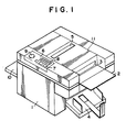
- Fig. 1 is a perspective view of the exterior of the preferred embodiment of the stencil duplicator of the present invention;
- Fig. 2 is a schematic structural part sectional side view showing the internal mechanisms of the stencil duplicator shown in Fig. 1 in a certain operational state; and
- Fig. 3 is a schematic structural part sectional side view, similar to Fig. 2, showing the same mechanisms in a different stage of their operating.
- The present invention will now be described with reference to the preferred embodiment thereof, and with reference to the appended drawings. Fig. 1 shows the preferred embodiment of the stencil duplicator of the present invention in overall exterior perspective view. In this figure, the
reference numeral 1 denotes a cabinet assembly of the stencil duplicator, which contains within it both a stencil making means for making a stencil master from an original and also a stencil printing means for printing multiple copies from said stencil master. At the front side of thecabinet assembly 1 in the drawing there is provided an original insertion table 2 for placing an original on ready to be inserted into the duplicator in order to make a stencil master therefrom. Below the insertion table 2 there is provided an output stacker 4 for receiving a stack of multiple printed copies made by the duplicator, and on the rear side of the cabinet assemly 1 there is provided apaper loading tray 10 for providing to the stencil duplicator a supply of blank paper which is to be used for printing on. Anupper cover 11 which is removable closes the upper side of thecabinet assembly 1. In thisupper cover 11 there is formed anoriginal insertion slot 3, located just above that edge of the original insertion table 2 which is joined to thecabinet assembly 1, for passing said original laid on the table 2 into the interior of the stencil duplicator; and further there is formed anoriginal ejection slot 5 through which, once it has been finished with, said original is ejected from the inside of the stencil duplicator. At a side upper portion thereof thecabinet assembly 1 is provided with anoperating panel 6. Thisoperating panel 6 has various control such as dials and buttons and switches activated by touch panels or the like incorporated therein, including for example a start button 7, a printquantity setting keyboard 8, and a print density adjustment dial 9, and is used by the operator of the stencil duplicator for controlling various functions thereof, such as for example how many copies should be printed from an original and of what intensity these copies should be, as well as for starting stencil printing. The output electrical signals from theoperating panel 6 are dispatched to a control system for the stencil duplicator which will be described with regard to its function hereinafter. However, as will be explained later, the constructional details of this control system for the stencil duplicator, and of thecontrol panel 6, do not form part of the present invention, and will not be further particularly described herein, since based upon the disclosures herein various possible structures for this control system, etc., will be readily conceived of by one of ordinary skill in the control art. - Figs. 2 and 3 show the internal mechanisms within the stencil duplicator of Fig. 1 in detail in part sectional schematic side view, in two different operational conditions as will be explained in detail later.
- In these figures, the
reference numeral 20 denotes a printing drum, which is formed as a hollow cylinder and is rotatably supported on a main frame not shown in the figures by arrangements which are also not shown in a generally horizontal orientation, and is thus rotatable about itscentral axis 20c; this supporting need not be axial, but may be on a combination of rollers which roll on the outside end edges of theprinting drum 20, for example. Thisprinting drum 20 is formed with multiple small perforations through its cylindrical surface from the space inside it to the outside. A clamp means generally designated as 21 is provided on the outside cylindrical surface of theprinting drum 20, extending generally along a generator thereof and thus only visible in transverse section in the figures, for clamping the leading edge of a piece of stencil master material to theprinting drum 20 along said generator. - In more detail, this clamp means 21 comprises a permanent magnet strip 22 which is fixed to the outer surface of said
printing drum 20 extending along a generator thereof, in fact constituting the flat upper surface of a stage 22a. The long edge of a clamp strip 24 made of magnetically attractable material is hinged by a hinge shaft 23 along the long edge parallel to the generators in the anticlockwise direction of theprinting drum 20 in the figure of the stage 22a. Thus, the clamp strip 24 can be pivoted to and fro relative to theprinting drum 20 around the hinge shaft 23, either in the clockwise direction in the figures so as to be applied against the permanent magnet strip 22 and so as to be magnetically held thereto, or in the anticlockwise direction in the figures so as to be removed from the permanent magnet strip 22. At one end of the hinge shaft 23 there is fixedly mounted agear wheel 25, and thisgear wheel 25 is selectively meshed, when theprinting drum 20 is in the rotational position shown in Fig. 2 which hereinafter will be called the base rotational position, with another gear wheel 27 which is rotatably supported on one end of a lever 26. The lever 26 is pivoted at a central portion thereof to the aforesaid main frame (not shown) of the mechanism by apivot 28, is biased in the anticlockwise direction in the figures by atension spring 30, and is selectively driven in the clockwise direction in the figures by asolenoid 29 which is attached to the other end of said lever 26. - Thus, when the
solenoid 29 is not supplied with actuating electrical energy, then the lever 26 is rotated by the biasing action of thetension spring 30 in the anticlockwise direction so as irrespective of the rotational position of theprinting drum 20 positively to ensure disengagement of the gear wheel 27 from thegear wheel 25; but, on the other hand, when thesolenoid 29 is supplied with actuating electrical energy, then the lever 26 is rotated by the action of saidsolenoid 29 in the clockwise direction in the figure against the biasing action of thetension spring 30 which is overcome so as to approach the gear wheel 27 towards the central axis of theprinting drum 20, and so as, if theprinting drum 20 is in its shown base rotational position, to drivingly engage the gear wheel 27 with thegear wheel 25. In this position, if the gear wheel 27 is appropriately rotated by anelectric motor 31, which is provided for the purpose of driving it, in the clockwise or the anticlockwise rotational direction respectively, then thegear wheel 25 and the hinge shaft 23 and the clamp strip 24 are thereby rotated in the anticlockwise or the clockwise rotational direction respectively, and can be positioned to any appropriate one of three rotational positions: a first so called clamping position in which the clamp strip 24 is applied to and is magnetically held by the permanent magnet strip 22; a second intermediate so called clamp ready position as shown in Fig. 2 in which the clamp strip 24 is removed from the permanent magnet strip 22 but only makes an acute angle therewith; and a thid so called fully unclamped position in which the clamp strip 24 is pivoted approximately 180° away from the permanent magnet strip 22. Thesolenoid 29 and theelectric motor 31 are selectively and appropriately supplied with actuating electrical energy by the control system for the stencil duplicator to be functionally described presently. - This clamp means 21 has been developed by various colleagues of the present inventors, along with some of the present inventors, in the workshops of the company to which the present patent application is assigned; should more details regarding said clamp means 21 be required, reference should be made to Japanese Patent Application No. Sho 57-207217, which is assigned to the same assignee as the present application.
- The
printing drum 20 is drivingly coupled to a sprocket wheel 34a which is coaxially coupled thereto, and this sprocket wheel 34a is drivingly coupled by anendless chain 32 to anothersprocket wheel 34b which is selectively rotated by anelectric motor 33. Theprinting drum 20 is thus selectively rotated, in the anticlockwise direction as seen in the figure only, by theelectric motor 33, according to the operation of the aforementioned control system which selectively powers theelectric motor 33, either continuously or in step motion as appropriate as will be explained later. - In the inside space within the
printing drum 20 there is provided a printing ink supply means, generally designated as 35, for steadily providing a supply of printing ink to the inside surface of theprinting drum 20. This ink supply means comprises anink supply roller 36 which is mounted so as to be rotatable about itscentral axis 37, and adoctor roller 38 which is also mounted so as to be rotatable about its central axis parallel to saidcentral axis 37 of theink supply roller 36, with a certain small gap being present between saiddoctor roller 38 and saidink supply roller 36. During operation of the duplicator, an elongated pool A of viscous printing ink is maintained as resting in the niche formed by the upper surfaces of thedoctor roller 38 and theink supply roller 37, and theink supply roller 36 is rotated in the counterclockwise direction in the figures at a speed which causes its surface to move at the same speed as that of the inside surface of theprinting drum 20 which it touches, while thedoctor roller 38 is rotated in the clockwise direction as seen in the figures at an appropriate rotational speed; and this rotation of theink supply roller 36 and thedoctor roller 38 constantly churns up the ink in the pool A and steadily entrains a supply thereof in a layer of substantially uniform thickness down through said gap between saiddoctor roller 38 and saidink supply roller 36, around saidink supply roller 36, and onto the inside surface of said printing drum. This ink is then used for printing copies as will be explained hereinafter. - This ink supply means 20 has been developed by various colleagues of the present inventors, along with some of the present inventors, in the workshops of the company to which the present patent application is assigned; should more details regarding said ink supply means 20 be required, reference should be made to Japanese Patent Applications Nos. Sho 53-128043 (1978), Sho 55-126934 (1980), and Sho 57-122589 (1982), all of which are assigned to the same assignee as the present application.
- Below the
printing drum 20 and parallel thereto there is provided a press roller 40, which is rotatably supported on one end of alever 42 by apivot 41. Thelever 42 is pivoted at a central portion thereof to the aforesaid main frame (not shown) of the mechanism by apivot 43, is biased in the clockwise direction in the figures by atension spring 47, and is selectively driven in the anticlockwise direction in the figures by a cam 46 mounted on acam shaft 45 which presses against acam follower roller 44 mounted on saidlever 42. - Thus, when the cam 46 presses the
cam follower roller 44 upwards in the figure against the biasing action of thetension spring 47 which is overcome, by being rotated to a position such as that shown in the figure, then thelever 42 is rotated by the biasing action of thetension spring 47 in the clockwise direction so as to remove the press roller 40 from the surface of theprinting drum 20; but, on the other hand, when the cam 46 allows thecam follower roller 44 to move downwards in the figure, by being rotated to a position about 180° from that shown in the figure, then by the biasing action of thetension spring 47 thelever 42 is rotated in the clockwise direction in the figure so as to approach the press roller 40 towards the surface of theprinting drum 20 to press against it. As will be understood later, during the stencil master ejection and attachment operations, the cam 46 is rotated to the position shown in the figures so as to remove the press roller 40 from the surface of theprinting drum 20; while, during the operation of printing multiple copies from a stencil master, the cam 46 is rotated in synchronism with the rotation of theprinting drum 20, so as to press the press roller 40 against the surface of theprinting drum 20 during substantially all phases of the revolution of theprinting drum 20 except during the passing of the clamp means 21 past said press roller 40, at which time said press roller 40 is removed from the surface of theprinting drum 20 so as to let the clamp means 21 move past. - The
paper loading tray 10 is substantially horizontal and is slidably mounted on and movable in the vertical direction with respect to the frame (not shown but schematically suggested by the double dotted lines) of the stencil duplicator. On thepaper loading tray 10 there is provided an electric motor not shown in the figure, which is selectively powered from the aforementioned control system, and which drives apinion 48 which is meshed with a vertically extendingfixed rack 49. Thus, according to the rotation of the aforesaid electric motor in the one or the other direction, the paper table 10 can be raised or lowered with respect to the frame of the stencil duplicator. A vertically extendingstop plate 50 is provided at the right hand side of the paper table 10, and as shown in the figure during the operation of the stencil duplicator a stack P of printing stock paper is laid on thepaper loading tray 10 with the right sides of the sheets thereof abutted against thestop plate 50 so as to line up said sheets. The operation of the aforesaid motor which drives thepinion 48 is controlled by the control system in response to the amount of printing paper remaining on thepaper loading tray 10, so as to appropriately position thepaper loading tray 10 to always keep the right hand edge of the uppermost one of the stack P of sheets of printing paper against the lower edge of apaper feed roller 60 which is rotatably mounted via ashaft 59 to the frame of the stencil duplicator and is selectively driven in the anticlockwise direction in the figures by an electric motor not shown in the figures controlled by the aforesaid control system. Thispaper feed roller 60 is constructed of a material such as rubber or artificial rubberwhich has a high coefficient of friction, and when thus rotated pulls the top sheet of paper of the stack P on thepaper loading tray 10 and, in combination with apress pad 61 which is biased against saidpaper feed roller 60, feeds said sheet of paper rightwards in the figure betweenguide plates 65 and 66 and through a register roller device 62 next to the press roller 40, comprising adrive roller 63 and a follower roller 64 which are rotated in synchronism with the rotation of theprinting drum 20 and are started to rotate when theprinting drum 20 is in a certain rotary position. Thus said sheet of paper is at an appropriate time, under control of the control system, fed in between the press roller 40 and theprinting drum 20. - Near the surface of the
printing drum 20, and on the other side of the press roller 40 from the register roller device 62, there is provided a peel offclaw 67, which is pivotable by a means not shown in the figure which is controlled by said control device for the stencil duplicator, so that its free claw end is either approached close to the surface of the printing drum 20 (possibly into a groove formed thereon) or is withdrawn away from the surface of theprinting drum 20. When the claw end of saidclaw 67 is thus approached towards saidprinting drum 20, it is appropriately positioned to scoope a sheet of paper off from the surface of theprinting drum 20 as saidprinting drum 20 revolves in the anticlockwise direction in the figure and to direct said sheet of paper into the output stacker 4, into which said sheet of paper is thrown by its inertia as it is impelled tangentially off from theprinting drum 20. - The operation of printing multiple copies from a stencil master, using the paper feed and removal means and the ink supply means described above, which has been adumbrated in the preceding structural description, will be explained in detail. Before this operation is commenced, a stencil master perforated with a pattern of holes corresponding to the marks on an original is wrapped securely around the
printing drum 20, with its leading edge gripped and held along a generator of saiddrum 20 by the clamp means 21, which holds it between the clamp strip 24 and the permanent magnet strip 22. - First, the control system activates the
paper feed roller 60 and rotates it in the anticlockwise direction in the figure, so that pulls the top sheet of paper off the stack P on thepaper loading tray 10 and feeds its leading edge in between therollers 63 and 64 of the register roller device 62. Next, the control system rotates theprinting drum 20 anticlockwise in the figure, and at an appropriate time rotates the cam 45 (as has already been explained) so as to raise the press roller 40 away from theprinting drum 20 so as to allow the clamp means 21 to pass said press roller 40, and just subsequently to this the control system again rotates thecam 45 so as to press the press roller 40 against the surface of theprinting drum 20 with the part of the stencil master just after the leading edge thereof interposed therebetween, and at the same time starts to rotate therollers 63 and 64 of the register roller device 62 (and also rotates the paper feed roller 60) so as to feed the leading edge of said next sheet of printing paper between the press roller 40 and the stencil master wrapped around theprinting drum 20. Thus the rolling contact of the press roller 40 and theprinting drum 20 sucks in the paper sheet and squeezes it against the stencil master progressively, as thedrum 20 and the press roller 40 rotate. Meanwhile, the above describedink supplying means 35 has been steadily supplying ink to the inside surface of theprinting drum 20, and this ink has been percolating through the multiple small perforations in theprinting drum 20 to cover the inside surface of the printing master, and under the squeezing effect of the press roller 40 this ink is squeezed through the perforations of the stencil master (whose pattern corresponds to that on an original which was used for cutting the stencil master as will be described later) and becomes applied to the inner surface of the sheet of printing paper progressively according to said original pattern as the paper passes through between the press roller 40 and theprinting drum 20. The leading edge of the paper comes into contact with the point portion of theclaw 67, which is approached to theprinting drum 20 by the control system at this time, and is peeled and scopped away from the stencil master and directed outwards towards the output stacker 4. When the printing paper has completely passed through between the press roller 40 and theprinting drum 20, thus, it is ejected and comes to rest in the output stacker 4. - This completes the printing process for one sheet of paper. This printing process is typically repeated many times to print many printed copies from one stencil master, according to the instructions given to the control system from the
control panel 6. Now the arrangements for making an appropriately perforated stencil master, for wrapping in onto theprinting drum 20, and for removing it therefrom after the printing process has been completed and disposing of it, will be explained in detail. - A stencil making means generally designated by the
reference numeral 70, for perforating a stencil master in a pattern corresponding to the pattern on an original, is provided at the upper part of the stencil duplicator, on the opposite side from thepaper tray 10. This stencil making means 70 includes anexposure stage 74 and apressure plate 75 located directly above theexposure stage 74; theexposure stage 74 is mounted to the main frame of the device (not shown) so as to be slidable in the verticl direction, and thepressure plate 75 is fixed to theupper cover 11 of the stencil duplicator. Theexposure stage 74 comprises alight box 71 which is open at the top, a rectangularlight transmitting plate 72 made of glass which closes said open top of thebox 71, and alight source 73 such as a xenon flash tube mounted within thelight box 71 so as to direct rays in the upwards direction, when so controlled to do so by the control system for the stencil duplicator. Thepressure plate 75 and the glasslight transmitting plate 72 directly oppose one another and are both substantially parallel, and the face of thepressure plate 75 opposing saidlight transmitting plate 72 is provided with acushion member 76 of resilient spongelike material. To a lower portion of theexposure stage 74 there is fixed the upper end of acam follower member 77, and the lower end of thiscam follower member 77 is formed as a cam pad which rests against the face of arotatable cam 78. Thecam 78 is selectively rotated by anelectric motor 79 in the clockwise and/or the anticlockwise direction, as appropriate, saidelectric motor 79 being controlled by the overall control system for the stencil duplicator, and thereby thecam follower member 77 drives theexposure stage 71, so that saidexposure stage 71 either is positioned to a lower position, as shown in Fig. 2, in which the glasslight transmitting plate 72 is removed from thecushion member 76 on thepressure plate 75 with a certain gap being left therebetween, or is positioned to an upper position, as shown in Fig. 3, in which the glasslight transmitting plate 72 is pressed upwards against thecushion member 76 on thepressure plate 75, possibly with the intervention of an original and a piece of stencil master as will be explained later. - This stencil making means 70 has been developed by various colleagues of the present inventors, along with some of the present inventors, in the workshops of the company to which the present patent application is assigned, should more details regarding said stencil making means 70 be required, reference should be made to Japanese Patent Applications Nos. Sho 54-97944 (1979) and Sho 55-50078 (1980), both of which are assigned to the same assignee as the present application.
- Under the original insertion table 2 there is provided a stencil master sheet
material storage section 80, in which a roll of stencil master material S is kept as wound upon abobbin 81. The outer edge of the original insertion table 2 protrudes to the outside of the stencil duplicator through theoriginal insertion slot 3 as shown in Fig. 1, and the inner edge of the original insertion table 2 is at substantially the same height and opposed to the outer edge of the gap formed between theexposure stage 71 and thepressure plate 75. Between said inner edge of the original insertion table 2 and the thus defined outer side of the stencil making means 70 is provided a stencil master and original moving means 140, for feeding stencil master from said roll of stencil master to the stencil master making means 70, which is constructed as follows. A lower roller 82 is freely rotatably mounted to the frame (not shown) of the stencil duplicator, and anupper roller 85 is rotatably mounted to the free end of. a first L-shaped lever 84, the other end of which is pivoted via a pivot 83 to theupper cover 11. Alug 86 is provided extending from the free portion of said first L-shaped lever 84, which is biased in the anticlockwise direction by the force of gravity acting thereon, so as to approach theupper roller 85 towards the lower free roller 84. A second L-shapedlever 88 is pivoted to the frame of the stencil duplicator by a pivot 87, and is biased in the clockwise direction in the figures by atension coil spring 89 while being selectively driven in the anticlockwise direction by asolenoid 90 controlled by the overall control system forthe'stencil duplicator; and the other end of this second L-shapedlever 88 selectively is abutted against saidlug 86 on said first L-shaped lever 84. Thus, when saidsolenoid 90 is not supplied with actuating electrical energy, then as shown in Fig. 2 under the biasing action of thetension coil spring 89 the second L-shapedlever 88 is driven in the clockwise direction in the figures so that its free end pushes saidlug 86 upwards and moves the first L-shaped lever in the clockwise direction in the figure so as to raise theupper roller 85 away from the lower roller 82 and leave a certain gap therebetween; but, when on the other hand saidsolenoid 90 is supplied with actuating electrical energy, then as shown in Fig. 3 against the biasing action of thetension coil spring 89 which is overcome it drives the second L-shapedlever 88 in the anticlockwise direction in the figures, so that the free end of saidfirst lever 88 releases saidlug 86 and allows saidlug 86 to move downwards so that the first L-shaped lever moves in the anticlockwise direction in the figure so as to lower saidupper roller 85 down to touch against said lower roller 82 and close said gap. - Just between the combination of the upper and
lower rollers 82 and 86 and the outer side of the stencil making means 70 is provided aphotosensor system 107 of a per se well known sort, which supplies a signal to the control system for the stencil duplicator to indicate whether an original is intercepting light which is being passed between components of saidphotosensor system 107 across the entrance to the gap between theexposure stage 71 and thepressure plate 75 of the stencil making means 70. - Extremely close to the inner edge of the gap formed between the
exposure stage 71 and thepressure plate 75, between theprinting drum 20 and the thus defined inner side of the stencil making means 70, is provided an original and master separation andfeed device 91, for separating a perforated stencil master from an original to which, as will be seen later, said perforated stencil master is stuck, at this stage in the apparatus. This separation andfeed device 91 comprises anupper roller 93 rotatably mounted to theupper cover 11 and alower roller 92 parallel to and in contact with and rolling against saidupper roller 93 and rotatably mounted on the frame (not shown) of the stencil duplicator. Anelectric motor 94 controlled by the overall control system for the stencil duplicator selectively rotationally drives thelower roller 92 in the anticlockwise direction as seen in the figure (thus driving theupper roller 93 in the clockwise direction at the same time). Further, at an intermediate point in the power transmission path between saidelectric motor 94 and thelower roller 92 there is provided a one way clutch (not shown) which, when theelectric motor 94 is not being operated, allows thelower roller 92 to be rotated in the anticlockwise direction (thus driving theupper roller 93 in the clockwise direction at the same time) with a certain amount of resistance. The line where the lower andupper rollers exposure stage 71 and the pressure plate 75 (i.e. the outlet slot of the- stencil making means 70), and thus, when as seen in Fig. 3 a piece of stencil master material S is passed between theexposure stage 71 and thepressure plate 75 and is also passed between the lower andupper rollers guide plates guide plates original ejection slot 5 at the exterior of the stencil duplicator. - Between the stencil master and original separation and
feed device 91 and theprinting drum 20 there is provided a stencil master cutter means 96 for cutting off a piece of the stencil master S which has been perforated in a pattern corresponding to the original from which it has been separated at this stage in the apparatus. This cutter means 96 comprises a rotatablelower blade 97, mounted to the frame of the stencil duplicator, which is selectively rotated by anelectric motor 99, and a cooperatingupper blade 98. In more detail, the rotatablelower blade 97 in fact is formed as a cylinder with a blade projecting from the outer surface thereof and extending almost along one of its generators but in fact angled at a slight angle to the generators of said cylinder so as to make a slight spiral around the surface of said cylinder; said spiral not extending around the axis of the cylinder a very large angle, however. Theupper blade 98 is substantially straight, and is pivoted at its base to theupper cover 11 and biased by atension coil spring 145. Thus, when the lowerrotatable blade 97 is positioned to a position in which the blade thereof is on the lower side of the axis thereof, a certain space is present between said lowerrotatable blade 97 and theupper blade 98, so that a piece of stencil master S can conveniently be passed therebetween; but, when the lowerrotatable blade 97 is rotated through one revolution from this position in the counterclockwise direction in the figure, the blade edge thereof presses against the edge of the upper blade 98 (the point of contact therebetween sliding rapidly in the direction perpendicular to the drawing paper in Figs. 2 and 3), slightly dispacing saidupper blade 98 against the biasing action of thetension coil spring 145, and quickly and efficiently slices transversely across said stencil master. The lowerrotatable blade 97 is rotatably coupled via abelt 118 to thelower roller 92 of the original and master separation andfeed device 91, with the interposition of a one way clutch which is not shown, so that when the lowerrotatable blade 97 rotates thelower roller 92 is forced to rotate, but not vice versa. - Between the stencil master cutter means 96 and the
printing drum 20 there is provided a stencil master transport means 150 for approaching the leading edge of the stencil master to the clamp means 21 on theprinting drum 20. This stencil master transport means 150 comprises: an upper guide plate 100; a lower guide plate 101 provided below and parallel to said upper guide plate 100 with a gap being left therebetween, the edges on the left in the figure of the upper and lower guide plates 100 and 101 lying close to theprinting drum 20 and parallel to the generators thereof; and ablower fan 102, which when operated blows from a position diagonally above said edges of the upper and lower guide plates 100 and 101 near theprinting drum 20 towards said printingdrum 20. Thisblower fan 102 is controlled by the control system for the stencil duplicator. - This stencil master transport means 150 has been developed by various colleagues of the present inventors, along with some of the present inventors, in the workshops of the company to which the present patent application is assigned; should more details regarding said stencil master transport means 150 be required, reference should be made to Japanese Patent Application No. Sho 57-207218, which is assigned to the same assignee as the present application.
- On the
upper cover 11 there is provided a lightreflection type photosensor 103, which by reflected light is able to detect, when theprinting drum 20 is in its above described base rotational position as shown in Fig. 2 with the clamp means 21 opened, whether or not the leading edge of a piece of stencil master is present over the permanent magnet strip 22 on the stage 22a. Theupper cover 11 is pivotally supported by being fixed to the frame of the stencil duplicator (not shown) by apivot 12, and can either be pivoted in the clockwise direction in the figure to a closed position as shown in Figs. 1 and 2 in which it covers the upper opening of the body of the stencil duplicator and is held by a lock means 13, or in the anticlockwise direction in the figure to an open position approximately 90° from said closed position and extending upwards, in which opened position saidupper cover 11 is maintained by a form of per se conventional lock means, not shown. - On the other side of the
printing drum 20, at the upper part of the stencil duplicator, there is provided a stencil master removal and disposal means 110, for removing a used stencil master from theprinting drum 20 after all desired stencil printing from said stencil master has been completed. This stencil master removal and disposal means 110 comprises upper and lower drive axles 111 and 112 which extend parallel to one another and parallel to the generators of theprinting drum 20 and alongside it, the upper one 111 of these drive axles being selectively rotationally driven in the clockwise direction in the figure by an electric motor" 115 which is controlled by the overall control system for the stencil duplicator. On this upper drive axle 111 there are fixedly mounted a plurality of gear wheels 113 (only one of which can be seen in the figure) spaced out in the axial direction, and each of thesegear wheels 113 is meshed with a corresponding gear wheel 114 (only one of which can be seen in the figure) which is mounted on the lower drive axle 112, said gearwheels 114 being likewise spaced out in the axial direction on the lower drive axle 112. To the upper and lower drive axles 111 and 112 there are also respectively fixed a plurality of beater tags 116 and 117, which are made of rubber or a rubberlike material and which are elastic. Further, a peel off claw 120 is provided next to theprinting drum 20, which is formed as a lever pivoted at its central portion to the frame (not shown) of the stencil duplicator. Atension coil spring 122 biases the peel off claw 120 in the counterclockwise direction in the figure, while a solenoid 121 controlled by the control system for the stencil duplicator is arranged so as selectively to bias said peel off claw 120 in the clockwise direction in the figure. Thus, when the solenoid 121 is not supplied with actuating electrical energy, then the peel off claw 120 is rotated counterclockwise in the figure by the biasing action of thetension coil spring 122, so that the active end 120a of said peel off claw 120 is withdrawn from the surface of saidprinting drum 20; but, when the solenoid 121 is supplied with actuating electrical energy, then the peel off claw 120 is rotated thereby clockwise in the figure against the biasing action of thetension coil spring 122 which is overcome so that said active end 120a of said peel off claw 120 is approached very close to the surface of saidprinting drum 20. - The stencil master removal and disposal means 110 further comprises an
upper guide plate 123 and alower guide plate 124, in between which a used stencil master is fed by being passed between thegear wheels 113 and 114 after being somewhat crushed therebetween; and towards the left in the figure of the gap between said twoguide plates lateral feed device 125. Thisfeed device 125 comprises asupport shaft 126 on which a plurality of rubber or rubber like rollers 127 are fixedly mounted, and also comprises aserrated metal roller 128, against which said rubber like rollers 127 are frictionally engaged, and which is selectively rotationally driven by anelectric motor 132 via ashaft 129 and twogear wheels electric motor 132 being controlled by the control system for the stencil duplicator. Thus, when saidelectric motor 132 is operated, and when said used stencil master is fed against the rollers 127 by thegear wheels 113 and 114, said used stencil master is further entrained between the rollers 127 and themetal roller 128 and is fed in the direction perpendicular to the drawing paper in Figs. 2 and 3 in the direction away from the viewer, while being further crushed, so as to be finally disposed of in a stencil master disposal box not shown in the figures. - This stencil master removal and disposal means 110 has been developed by various colleagues of the present inventors in the workshops of the company to which the present patent application is assigned; should more details regarding said stencil master removal and disposal means 110 be required, reference should be made to Japanese Patent Application No. Sho 55-17391 (1980) and Japanese Utility Model Applications Nos. Sho 54-179596 (1979) and Sho 57-63378 (1982), all of which are assigned to the same assignee as the present application.
- The control device for the stencil duplicator, which selectively provides actuating electrical energy for all these above described electric motors, solenoids, etc., and which receives electrical signals from the above described sensors and controls, as well as having other functions, comprises a microcomputer and other associated circuitry; but constructional details of this control system for the stencil duplicator, and of the
control panel 6 and so on, do not form part of the present invention, and will not be further particularly described herein except in terms of its function, since based upon the disclosures herein various possible structures for this control system, etc., to provide the described function, will be readily conceived of by one of ordinary skill in the control art. - Now the operation of the stencil duplicator for removing an old used stencil master wrapped around the
printing drum 20, for charging a new roll of stencil master when so required, and for preparing a new stencil master from a new original and for attaching said new stencil master around theprinting drum 20 for printing, will be explained in detail. - First, with regard to the process of removing an old used stencil master, suppose that such a stencil master which has been already used for stencil printing as explained earlier and which is no longer required is still wrapped around the outer surface of the
printing drum 20, being clamped thereto along its leading edge by the clamp means 21. For removal, first theprinting drum 20 with the used stencil master S therearound is positioned by the operation of the control system for the duplicator to its base rotational position as seen in Fig. 2, and thesolenoid 29 is supplied with actuating electrical energy, so as to rotate the lever 26 by the action of saidsolenoid 29 in the clockwise direction in the figure against the biasing action of thetension spring 30 which is overcome so as to drivingly engage the gear wheel 27 with thegear wheel 25. Next, the gear wheel 27 is appropriately rotated by theelectric motor 31 in the clockwise rotational direction so as to rotate thegear wheel 25 and the hinge shaft 23 and the clamp strip 24 in the anticlockwise rotational direction from their previous positions (in which the clamp strip was magnetically held against the permanent magnet strip 22 and was holding the used stencil master) so as now to position the clamp means 21 to the fully unclamped position in which the clamp strip 24 is pivoted approximately 180° away from the permanent magnet strip 22 and thus completely releases the used stencil master. Next, after this has been completed, the control system turns thedrive motor 31 for the gear wheel 27 off and deenergizes thesolenoid 29 so as to disengage the gear wheel 27 from thegear wheel 25 by turning the lever 26 anticlockwise from the point of view of the figure, and then energizes the solenoid 121 and starts theelectric motor 115 and theelectric motor 132 operating. This causes the peel off claw 120 to be rotated clockwise in the figure against the biasing action of thetension coil spring 122 which is overcome so that the active end 120a of the peel off claw 120 is approached very close to the surface of saidprinting drum 20. Next, the control system slowly rotates theprinting drum 20 through one full revolution in the anticlockwise direction in the figure, so that the end 120a of the peel off claw 120 scoops the used stencil master off from theprinting drum 20 and directs said used stencil master between thegear wheels 113 and the gear wheels 114 meshed therewith. As this happens, the stencil master is crumpled and mashed by thesegear wheels 113 and 114, and is further squashed up by the action of the beater tags 116 and 117 as they thrash it. Then the somewhat mashed up stencil master is ejected to the left of thegear wheels 113 and 114 in the figure between theguide plates lateral feed device 125, in which said used stencil master impacts against the rollers 127 and is entrained between the rollers 127 and themetal roller 128 and is crushed thereby as well as being fed in the direction perpendicular to the drawing paper in Figs. 2 and 3 in the direction away from the viewer, so as to be finally disposed of in the aforementioned stencil master disposal box, not shown. When this disposal has been completed, the control system stops rotating theprinting drum 20 when saidprinting drum 20 has returned to its base rotational position as seen in Fig. 2, deactivates theelectric motors - Now, on the other hand, when the stencil duplicator is to be loaded with a new roll of stencil master, the locking
device 13 is released and theupper cover 11 is opened by being pivoted around thehinge 12. At this time, theroller 85, thepressure plate 75, theupper roller 93, and theupper blade 98 are all raised up. Thereby, a new roll of stencil master S can easily be loaded in the stencilmaterial storage section 80. Then the leading edge of the stencil master S is pulled by the operator of the duplicator and is unrolled from the roll of stencil material, and then as this leading edge is pulled out the end portion of the roll of stencil material is laid over the roller 82, thelight transmitting plate 72, theroller 92, and thelower blade 97 in that order (thelower blade 97 being positioned with the edge thereof downwards at this time), with the leading edge of the stencil master being inserted between the guide plates 100 and 101, on the guide plate 101. For convenience of adjustment, the upper surface of the guide plate 101 may be provided with an index line for showing the proper loading position for the front or leading edge for the stencil master, and in such a case at this time of charging the new roll of stencil master the positioning of the leading edge of the stencil master is made by laying it against this index line. Then theupper cover 11 is closed by being pivoted downwards, and is secured by the lockingdevice 13. Thus the new roll of stencil material S is charged into the duplicator, with the end portion thereof being gripped between therollers 82 and 85 and also between therollers - Now the operation of making a new stencil master according to the pattern on an original and securing said new stencil master around the
printing drum 20, ready for printing, will be explained. - First, the original O is placed face down by hand on the original insertion table 2, as shown in Fig. 2, and is pushed in through the
original insertion slot 3 for a certain predetermined distance, which may be determined, for example, by aligning the back edge of the original O against the appropriate one of a set of index lines (one corresponding to each possible size for an original) inscribed on the upper surface of the original insertion table 2. At this time, thesolenoid 90 is not energized by the control system for the stencil duplicator, so that theroller 85 is raised and a certain gap is present between saidroller 85 and the roller 82; and thus the original O passes through this gap between therollers 85 and 82, sliding on top of the stencil master sheet S which as explained above also is passed through this gap, and the leading edge of the original O is approached to the right hand side of the stencil making means 70, and is inserted between the light transmittingplate 72 of theexposure stage 74 and thepressure plate 75, on top of the stencil master S also therebetween. - The
photosensor 107 detects this insertion of the original 0, and sends a signal representative thereof to the control system. When the insertion of the original O has been properly accomplished, the control system energizes thesolenoid 90, and this, as explained above, causes theroller 85 to be lowered so as to rest against the roller 82 with the original O and the stencil master sheet S clamped therebetween. At this time, theprinting drum 20 is positioned by the means for moving it, under control of the control system, to its base rotational position, if it is not there already, and thesolenoid 29 is supplied with actuating electrical energy so as to rotate the lever 26 by the action of saidsolenoid 29 in the clockwise direction in the figure against the biasing action of thetension spring 30 which is overcome so as to drivingly engage the gear wheel 27 with thegear wheel 25. Next, the gear wheel 27 is appropriately rotated by theelectric motor 31 in the appropriate rotational direction and by the appropriate amount to rotate thegear wheel 25 and the hinge shaft 23 and the clamp strip 24 so as to position the clamp means 21 to the previously described so called clamp ready position as shown in Fig. 2 in which the clamp strip 24 is removed from the permanent magnet strip 22 but only makes an acute angle therewith. This state of the apparatus is shown in Fig. 2. - Next, the control system drives the
electric motor 94, so as to rotate theroller 92 counterclockwise in the figure and theroller 93 clockwise and so as to drive the stencil master material S through between theserollers blowerfan 102, so as to blow an air current from diagonally above the left hand edges in the figures of the upper and lower guide plates 100 and 101 towards theprinting drum 20. This air current lightly grips the leading edge of the stencil master S as it is advanced by the aforesaid rotation of therollers - When this leading edge of the stencil master S is properly thus inserted into the gap between the permanent magnet strip 22 and the clamp strip 24, then this fact is detected by the
photosensor 103, and the control system then stops operating theelectric motor 94, thus ceasing to advance the stencil master S. Further, the control system, while actuating thesolenoid 29 so as to drivingly engage the gear wheel 27 with thegear wheel 25, appropriately rotates the gear wheel 27 by theelectric motor 31 so as to rotate thegear wheel 25 and the hinge shaft 23 and the clamp strip 24 so as to position the clamp means 21 to the previously described so called clamping position as shown in Fig. 3 in which the clamp strip 24 is resting against and magnetically attracted to the permanent magnet strip 22, with the leading edge of the stencil master S clamped therebetween. When this has been accomplished, then the control system ceases to supply thesolenoid 29 with actuating electrical energy, so that the lever 26 is rotated in the anticlockwise direction in the figure by the biasing action of thetension spring 30 so as to disengage the gear wheel 27 from thegear wheel 25. - Now the apparatus is ready for the initial exposure for perforation of the stencil master along an initial strip thereof, the details of which are as follows. First, the
electric motor 79 is operated so as to rotate thecam 78, and so as to raise theexposure stage 74 upwards until thelight transmitting plate 72 thereof is pressed against thecushion member 76 on thepressure plate 75, with the sandwich of the stencil-master S under the original O squeezed between them. When this has been fully accomplished, the control device activates thelight source 73 within the exposure-stage 74, so as to illuminate the part of the downward facing side of the original 0 which is visible at this time through thelight transmitting plate 72 through the stencil master S squeezed thereagainst. This part of the original 0 has the form of a transverse strip thereon; generally, it does not include the whole of the pattern on the original for which copies are required to be made, but is only an initial or leading strip thereof. Because the radiation thus emitted from thelight source 73 engenders considerable heat in the dark portions of the origional O which are exposed thereto, this heat causes the portions of the stencil master sheet S pressed thereagainst to effectively disappear; these portions are melted and curl up, being reduced to vestigial or nonexistent remnants by the action of this heat. In other words, a portion of the stencil master sheet S is perforated by the per se well known thermal perforation process in a pattern corresponding to that on the aforesaid corresponding exposed strip of the original O. Once this perforation is completed, theelectric motor 79 is again energized so as to rotate thecam 78 this time in the reverse direction to that previously employed, and thereby theexposure stage 74 is lowered, thus releasing the squeezing of thelight transmitting plate 72 against thecushion member 76 on thepressure plate 75, and releasing the squeezing of the sandwich of the stencil master S under the original 0 between them. However, at this time, the stencil master S remains as adhered to the original 0, as an aftermath of the stencil perforation process; this is a per se well known property of the thermal perforation method. - Next, the
electric motor 33 is actuated by the control system, so as to rotate theprinting drum 20 slowly in the anticlockwise direction in the figure through a controlled angle. This state of the device is shown in Fig. 3. This operation pulls gently on the stencil master S, the leading edge of which is as explained above secured along the clamp stage 22a by the clamp strip 24 of the clamp means 21, and thereby the stencil master S is moved leftwards in the figures and is progressively wound around theprinting drum 20, more of said stencil master S being unrolled from the roll thereof in the stencilmaster storage section 80, and the original O is likewise moved leftwards in the figures, being as explained above adhered to the stencil master S over the portion thereof which has been exposed and perforated. At this time, the electric motor94 is not supplied with actuating electrical energy, and accordingly theroller 92 is not positively rotationally driven thereby; but according to the action of the aforementioned one way clutch therollers printing drum 20, and ensures that no wrinkles are allowed to form therein. During this motion of the stencil master S and the original 0, as the adhered together sandwich thereof moves out from the left hand side of the stencil making means 70, the stencil master S which is very flexible is as explained previously bent downwards through a sharp angle, almost a right angle, by the separation claw 95, as it approaches towards therollers guide plates original ejection slot 5, while the perforated portion of the stencil master S is moved towards theprinting drum 20 to be wound thereon. - This rotation of the
printing drum 20 and winding of the stencil master S thereon is continued for a predetermined angle, as mentioned above, until the exposed portions of the original 0 and the stencil master sheet S have just been moved away from thelight transmitting plate 72, with a new strip of the original 0 and a corresponding new strip of the stencil master S now located between the light transmittingplate 72 and thepressure plate 75; in fact, a small overlap strip between said old and new strips of the original O and the stencil master S is allowed to be present, and does not significantly deteriorate the quality of the stencil perforation process. At this point, the rotation of theprinting drum 20 is stopped by the control system, and the above described step of raising theexposure stage 74 of the stencil perforation means 70 is again performed, to again squeeze the sandwich of the next strip of the original 0 and the next strip of the stencil master S. Then again thelight source 72 is operated to expose and perforate this next stencil master strip; and again theexposure stage 74 is lowered and theprinting drum 20 is rotated through said certain predetermined angle. These steps of exposure and then pulling of the stencil master by rotation of theprinting drum 20 are alternatingly repeated a number of times, and in this way successive strips of the stencil master S are exposed and perforated in a pattern corresponding to that on the original 0, and the thus stepwise exposed and perforated stencil master S is progressively wound onto theprinting drum 20, while the original 0 is correspondingly progressively fed towards and out of theoriginal ejection slot 5. - This repeated exposure and winding process is carried on until the
photosensor 107 detects that the trailing edge of the original 0 has passed it, and after this the supply of electrical energy to thesolenoid 90 is terminated, thus causing theroller 85 to rise up away from the roller 82, and one last perforating exposure of the last portion of the original 0 is made. Then theexposure stage 74 is lowered for good, and the actuation of theelectric motor 79 is finally terminated; and next theprinting drum 20 is continuously rotated counterclockwise by themotor 33, while the original 0 becomes completely separated from the stencil master S which is being wound onto saidprinting drum 20; the original O may in fact be completely ejected from the machine through theoriginal ejection slot 5 by rollers or the like not shown in the figures. When the rotation of theprinting drum 20 has proceeded through a predetermined angle from the initial or base rotational position, said angle being appropriately nearly a full revolution such as an angle of 330° for example, then theelectric motor 99 is started by the control system and the lower orrotary blade 97 of the cutter means 96 is rotated through one full revolution so as to cut the stencil master S cleanly across with one transverse cut as explained above; during this cutting process, by the operation of the aforementioned one way clutch and thedrive belt 118, therollers printing drum 20 and so as to allow for a clean cut. After the actual cutting process, the returning of therotary blade 97 round to its lower position rotates therollers printing drum 20 is continued, thus finishing the wrapping of the perforated and cut stencil master S around the peripheray of saidprinting drum 20. In fact, during this initial wrapping rotation of theprinting drum 20, it is possible simultaneously to print the first copy from the new stencil master S wound therearound, even before the wrapping has been completely finished, in the fashion explained hereinabove; this first printed copy may advantageously be a proof copy. - The completes the explanation of preparing a new stencil master from a new original and of attaching said new stencil master around the printing drum for printing. The control system for the stencil duplicator may advantageously be arranged to operate in such a way that, if the start button 7 is pressed when the
photosensor 107 is detecting that no new original 0 is inserted into theoriginal insertion slot 3, then stencil printing is resumed using the old stencil master S which remains wrapped around theprinting drum 20 from a previous stencil printing operation. In other words, the operation of removing an old stencil master S from the periphery of theprinting drum 20 is advantageously arranged only to be performed when a new stencil master S is definitely required to be prepared, according to the insertion of a new original 0 in theoriginal insertion slot 3. - Thus, it is seen that the present invention provides an entirely automatic stencil duplicator which does not require any manual intervention for making stencil masters, for printing copies therefrom, and for disposing of the used stencil masters, and which can provide a high degree of pressure between an original and a piece of thermal stencil master material which is to be perforated according to the pattern on said original, in order to provide a high quality of stencil perforation with high resolution. Further, the problems described earlier with respect to the prior art of wrinkling in the stencil master material during the manufacture of a perforated stencil master, as well as during the process of wrapping the perforated stencil master onto the printing drum for subsequent printing therefrom, are avoided. Thus, this duplicator is able to be applied to the use of continuous roll thermal master sheet material, and does not require the provision of any reinforced header portions on the stencil masters for handling and fixing them. Further, during operation of this stencil duplicator, wrinkles in the stencil master material caused during the stencil perforation process are not caused to be accentuated during the process of wrapping the perforated stencil master onto the printing drum for subsequent printing therefrom due to tension provided in said perforated stencil material for the purpose of avoiding the generation of transverse wrinkles therein, but rather are smoothed out.
Claims (2)
Applications Claiming Priority (2)
| Application Number | Priority Date | Filing Date | Title |
|---|---|---|---|
| JP207216/82 | 1982-11-26 | ||
| JP57207216A JPS5996983A (en) | 1982-11-26 | 1982-11-26 | Mimeographic plate printer |
Publications (3)
| Publication Number | Publication Date |
|---|---|
| EP0110204A2 EP0110204A2 (en) | 1984-06-13 |
| EP0110204A3 EP0110204A3 (en) | 1984-07-25 |
| EP0110204B1 true EP0110204B1 (en) | 1988-05-11 |
Family
ID=16536161
Family Applications (1)
| Application Number | Title | Priority Date | Filing Date |
|---|---|---|---|
| EP83111160A Expired EP0110204B1 (en) | 1982-11-26 | 1983-11-08 | Stencil duplicator providing automatic stencil perforation, charging, printing, and disposal |
Country Status (4)
| Country | Link |
|---|---|
| US (1) | US4628813A (en) |
| EP (1) | EP0110204B1 (en) |
| JP (1) | JPS5996983A (en) |
| DE (1) | DE3376540D1 (en) |
Cited By (1)
| Publication number | Priority date | Publication date | Assignee | Title |
|---|---|---|---|---|
| US9415550B2 (en) | 2012-08-22 | 2016-08-16 | The General Hospital Corporation | System, method, and computer-accessible medium for fabrication miniature endoscope using soft lithography |
Families Citing this family (70)
| Publication number | Priority date | Publication date | Assignee | Title |
|---|---|---|---|---|
| JPS59104937A (en) * | 1982-12-08 | 1984-06-18 | Matsushita Electric Ind Co Ltd | Fully automatic plate making printing machine |
| JPS59188438A (en) * | 1983-04-11 | 1984-10-25 | Matsushita Electric Ind Co Ltd | Fully automatic plate making printer |
| JPS59188439A (en) * | 1983-04-11 | 1984-10-25 | Matsushita Electric Ind Co Ltd | Fully automatic plate making printing machine |
| JPS59188440A (en) * | 1983-04-11 | 1984-10-25 | Matsushita Electric Ind Co Ltd | Fully automatic plate making printing machine |
| JPS59188437A (en) * | 1983-04-11 | 1984-10-25 | Matsushita Electric Ind Co Ltd | Fully automatic plate making printing machine |
| GB2170150A (en) * | 1985-01-25 | 1986-07-30 | Gestetner Mfg Ltd | Stencil duplicator with integral stencil imager |
| GB2160151A (en) * | 1985-01-25 | 1985-12-18 | Gestetner Mfg Ltd | Combination stencil duplicator and stencil imager |
| JPH0615259B2 (en) * | 1985-04-05 | 1994-03-02 | 理想科学工業株式会社 | Roll type stencil printing base paper supply method |
| JPH0615258B2 (en) * | 1986-03-13 | 1994-03-02 | セイキ工業株式会社 | Paper feeder of printing machine |
| US4846057A (en) * | 1986-09-09 | 1989-07-11 | Ricoh Co., Ltd. | Screen printing machine with waste printing plate discharge means |
| JPS6349937U (en) * | 1986-09-17 | 1988-04-05 | ||
| JPS6374640U (en) * | 1986-10-31 | 1988-05-18 | ||
| JP2625437B2 (en) * | 1987-07-22 | 1997-07-02 | 株式会社リコー | Stencil printing machine |
| JPH0162040U (en) * | 1987-10-14 | 1989-04-20 | ||
| JP2728435B2 (en) * | 1988-06-22 | 1998-03-18 | 理想科学工業株式会社 | Stencil printing machine |
| US5235914A (en) * | 1988-08-19 | 1993-08-17 | Presstek, Inc. | Apparatus and method for imaging lithographic printing plates using spark discharges |
| US5237923A (en) * | 1988-08-19 | 1993-08-24 | Presstek, Inc. | Apparatus and method for imaging lithographic printing plates using spark discharges |
| JPH0717083B2 (en) * | 1989-07-24 | 1995-03-01 | デュプロ製造株式会社 | Multicolor printer |
| JPH081887Y2 (en) * | 1989-07-25 | 1996-01-24 | 理想科学工業株式会社 | Original plate carrier |
| JP2828473B2 (en) * | 1989-12-04 | 1998-11-25 | 理想科学工業株式会社 | Plate making and printing equipment |
| JP2828479B2 (en) * | 1990-02-02 | 1998-11-25 | 理想科学工業株式会社 | Processing apparatus and processing method for used thermosensitive stencil paper |
| JP2958038B2 (en) * | 1990-03-06 | 1999-10-06 | 理想科学工業株式会社 | Plate discharging device |
| US5048417A (en) * | 1990-05-04 | 1991-09-17 | Everroad Michael A | Compact apparatus for screen preparation and printing and method of use |
| WO1992007716A1 (en) * | 1990-11-01 | 1992-05-14 | Landsman Robert M | Printing press |
| US5253581A (en) * | 1990-12-29 | 1993-10-19 | Brother Kogyo Kabushiki Kaisha | Stamp device employing a heat sensitive stencil paper to be perforated by heat of a thermal head |
| US5329848A (en) * | 1990-12-29 | 1994-07-19 | Brother Kogyo Kabushiki Kaisha | Stamp device capable of perforating thermal stencil paper |
| DE69222225T2 (en) * | 1991-06-07 | 1998-01-29 | Riso Kagaku Corp | Printing device which produces a plate-shaped printing stencil |
| JP3280061B2 (en) * | 1992-03-13 | 2002-04-30 | 理想科学工業株式会社 | Stencil sheet feeding and discharging device |
| JPH089257B2 (en) * | 1992-06-18 | 1996-01-31 | 富士ゼロックス株式会社 | Plate making equipment |
| EP0583076B1 (en) * | 1992-07-16 | 1996-10-16 | Riso Kagaku Corporation | Stencil printing device |
| USRE35512F1 (en) * | 1992-07-20 | 1998-08-04 | Presstek Inc | Lithographic printing members for use with laser-discharge imaging |
| US5351617A (en) * | 1992-07-20 | 1994-10-04 | Presstek, Inc. | Method for laser-discharge imaging a printing plate |
| US5353705A (en) * | 1992-07-20 | 1994-10-11 | Presstek, Inc. | Lithographic printing members having secondary ablation layers for use with laser-discharge imaging apparatus |
| US5339737B1 (en) * | 1992-07-20 | 1997-06-10 | Presstek Inc | Lithographic printing plates for use with laser-discharge imaging apparatus |
| AU674518B2 (en) * | 1992-07-20 | 1997-01-02 | Presstek, Inc. | Lithographic printing plates for use with laser-discharge imaging apparatus |
| US5379698A (en) * | 1992-07-20 | 1995-01-10 | Presstek, Inc. | Lithographic printing members for use with laser-discharge imaging |
| US5476038A (en) * | 1993-02-02 | 1995-12-19 | Brother Kogyo Kabushiki Kaisha | Stamp apparatus |
| GB2275227B (en) * | 1993-02-23 | 1996-11-13 | Tohoku Ricoh Co Limited | Stencil duplication machine |
| JP3286644B2 (en) * | 1993-03-05 | 2002-05-27 | 理想科学工業株式会社 | Control device of stencil printing machine with plate discharging device |
| JPH0725004A (en) * | 1993-07-14 | 1995-01-27 | Riso Kagaku Corp | Image forming device |
| JP3466237B2 (en) * | 1993-09-09 | 2003-11-10 | 理想科学工業株式会社 | Method for producing solvent stencil stencil sheet |
| JPH0776189A (en) * | 1993-09-09 | 1995-03-20 | Riso Kagaku Corp | Method of manufacturing base paper for stencil printing |
| JP3466283B2 (en) * | 1993-09-13 | 2003-11-10 | 東北リコー株式会社 | Stencil making machine and master storage unit |
| JPH07108780A (en) * | 1993-10-14 | 1995-04-25 | Riso Kagaku Corp | Stencil printing base paper and perforating method thereof |
| JP3422826B2 (en) * | 1993-11-09 | 2003-06-30 | 理想科学工業株式会社 | Stencil printing machine |
| JPH07237782A (en) * | 1994-03-01 | 1995-09-12 | Riso Kagaku Corp | Stencil printer |
| JPH0848069A (en) * | 1994-08-08 | 1996-02-20 | Riso Kagaku Corp | Stencil printer |
| JPH0872383A (en) * | 1994-09-01 | 1996-03-19 | Riso Kagaku Corp | Stencil printing device and stencil printing base paper used in the device |
| JP3319893B2 (en) * | 1994-11-16 | 2002-09-03 | 理想科学工業株式会社 | Stencil printing machine |
| DE69512604T2 (en) * | 1994-11-21 | 2000-03-09 | Riso Kagaku Corp. O | Rotary stencil printing machine |
| JP3292427B2 (en) | 1994-11-25 | 2002-06-17 | 理想科学工業株式会社 | Stencil stencil starter for rotary stencil printing press |
| JP3877802B2 (en) * | 1995-05-02 | 2007-02-07 | 株式会社リコー | Emulsion ink and printing method using the same |
| CN1139496C (en) * | 1995-07-31 | 2004-02-25 | 东北理光株式会社 | Stencils and stencil punching equipment |
| GB2321877B (en) * | 1995-07-31 | 1998-10-21 | Tohoku Riko Kk | Stencil perforating device |
| GB2307883A (en) * | 1995-12-08 | 1997-06-11 | Gestetner Mfg Ltd | Consumable material management system |
| JP3957791B2 (en) * | 1995-12-22 | 2007-08-15 | 東北リコー株式会社 | Plate making writing device |
| JPH10128946A (en) * | 1996-10-30 | 1998-05-19 | Riso Kagaku Corp | Plate making equipment |
| JP3525319B2 (en) * | 1997-02-21 | 2004-05-10 | 理想科学工業株式会社 | Plate discharging device for rotary stencil printing press |
| US5992314A (en) * | 1997-06-30 | 1999-11-30 | Ncr Corporation | UV curable adhesive for stencil media |
| JP4180693B2 (en) * | 1997-11-21 | 2008-11-12 | 東北リコー株式会社 | Multicolor printing method and multicolor printing system |
| JP3761698B2 (en) * | 1997-12-24 | 2006-03-29 | 理想科学工業株式会社 | Stencil printing machine |
| US5992315A (en) * | 1998-02-25 | 1999-11-30 | Ncr Corporation | Thermal stencil master sheet with epoxy/coreactant adhesive and method for producing the same |
| JP3294555B2 (en) * | 1998-08-31 | 2002-06-24 | 理想科学工業株式会社 | Stencil printing machine |
| DE60010581T2 (en) * | 1999-07-09 | 2004-09-16 | Riso Kagaku Corp. | Stencil printing machine. |
| US6505551B1 (en) | 1999-10-05 | 2003-01-14 | Riso Kagaku Corporation | Stencil printing machine having means to hold both ends of stencil sheet |
| JP3631929B2 (en) | 1999-11-11 | 2005-03-23 | 理想科学工業株式会社 | Stencil paper starting edge mounting device of rotary stencil printing machine |
| JP2001239735A (en) * | 2000-03-01 | 2001-09-04 | Riso Kagaku Corp | Stencil printing machine |
| US6742450B2 (en) * | 2001-07-27 | 2004-06-01 | Tohoku Ricoh Co., Ltd. | Stencil printer and method and device for making a master therefor |
| KR100608071B1 (en) * | 2005-06-28 | 2006-08-02 | 삼성전자주식회사 | A hinge device using magnetic force and an image input / output device provided with the hinge device |
| JP2007021913A (en) * | 2005-07-15 | 2007-02-01 | Tohoku Ricoh Co Ltd | Stencil process printing device |
Family Cites Families (10)
| Publication number | Priority date | Publication date | Assignee | Title |
|---|---|---|---|---|
| US612550A (en) * | 1898-10-18 | schwarz | ||
| US887063A (en) * | 1908-05-12 | Mcion James Douglas Carter | Rotary-duplicators. | |
| US700807A (en) * | 1901-12-21 | 1902-05-27 | Charles H Palmer | Machine for making paper-box blanks. |
| US934077A (en) * | 1907-08-19 | 1909-09-14 | Underwood Typewriter Co | Stenciling-machine. |
| US3788221A (en) * | 1970-12-15 | 1974-01-29 | Dick Co Ab | Stencil duplicator with master making and pneumatic handling features |
| CA977596A (en) * | 1971-12-28 | 1975-11-11 | Yoshio Tsuji | Imaged sheet or film and method and apparatus for preparing same |
| US4091727A (en) * | 1973-08-03 | 1978-05-30 | Asahi Dow Limited | Heat-sensitive copying method for preparation of printing stencils |
| GB1545726A (en) * | 1976-07-08 | 1979-05-16 | Sekisui Chemical Co Ltd | Electric discharge recording method and material |
| GB1579459A (en) * | 1976-08-26 | 1980-11-19 | Riso Kagaku Corp | Printing device for stencils |
| JPS6018969B2 (en) * | 1979-07-30 | 1985-05-14 | 理想科学工業株式会社 | split exposure device |
-
1982
- 1982-11-26 JP JP57207216A patent/JPS5996983A/en active Pending
-
1983
- 1983-11-08 EP EP83111160A patent/EP0110204B1/en not_active Expired
- 1983-11-08 DE DE8383111160T patent/DE3376540D1/en not_active Expired
-
1985
- 1985-10-22 US US06/789,367 patent/US4628813A/en not_active Expired - Lifetime
Cited By (1)
| Publication number | Priority date | Publication date | Assignee | Title |
|---|---|---|---|---|
| US9415550B2 (en) | 2012-08-22 | 2016-08-16 | The General Hospital Corporation | System, method, and computer-accessible medium for fabrication miniature endoscope using soft lithography |
Also Published As
| Publication number | Publication date |
|---|---|
| EP0110204A2 (en) | 1984-06-13 |
| DE3376540D1 (en) | 1988-06-16 |
| JPS5996983A (en) | 1984-06-04 |
| EP0110204A3 (en) | 1984-07-25 |
| US4628813A (en) | 1986-12-16 |
Similar Documents
| Publication | Publication Date | Title |
|---|---|---|
| US4628813A (en) | Stencil duplicator providing automatic stencil performation, charging, printing, and disposal | |
| JPS6255138A (en) | Intermittent feeder for continuous paper | |
| US5988061A (en) | Stencil printing method and printer using the same | |
| EP1129858A1 (en) | A stencil printing machine and a wrinkle preventing method on a stencil sheet of the stencil printing machine | |
| JPS59198185A (en) | Stencil-type plate-making printer | |
| JP3609493B2 (en) | Image forming apparatus | |
| JP2592618B2 (en) | Plate making and printing equipment | |
| JPH03110129A (en) | Laminator | |
| JP4392178B2 (en) | Stencil printing machine | |
| JPH02273Y2 (en) | ||
| US6792853B2 (en) | Stencil printer | |
| JPS5916788A (en) | Rolled-type heat-sensitive stencil paper | |
| JP3642820B2 (en) | Plate removing apparatus for stencil printing apparatus and plate discharging method using the same | |
| JP4260437B2 (en) | Stencil printing machine | |
| JPS622182Y2 (en) | ||
| JP4672874B2 (en) | Stencil printing machine | |
| JP4462707B2 (en) | Plate making apparatus and stencil printing apparatus | |
| JPH03110130A (en) | Laminator | |
| JP3659847B2 (en) | Plate removal equipment | |
| JPS6055817B2 (en) | Copy document automatic feeder | |
| JP3889591B2 (en) | Stencil printing machine | |
| JPH0611830Y2 (en) | Feeder for printing base paper | |
| JPS6317092A (en) | Thermal screen printing stencil | |
| JPH05254019A (en) | Laminating device | |
| JP4398609B2 (en) | Master clamp structure and stencil printing apparatus |
Legal Events
| Date | Code | Title | Description |
|---|---|---|---|
| PUAI | Public reference made under article 153(3) epc to a published international application that has entered the european phase |
Free format text: ORIGINAL CODE: 0009012 |
|
| PUAL | Search report despatched |
Free format text: ORIGINAL CODE: 0009013 |
|
| AK | Designated contracting states |
Designated state(s): DE FR GB |
|
| AK | Designated contracting states |
Designated state(s): DE FR GB |
|
| 17P | Request for examination filed |
Effective date: 19841227 |
|
| 17Q | First examination report despatched |
Effective date: 19860114 |
|
| R17C | First examination report despatched (corrected) |
Effective date: 19860214 |
|
| GRAA | (expected) grant |
Free format text: ORIGINAL CODE: 0009210 |
|
| AK | Designated contracting states |
Kind code of ref document: B1 Designated state(s): DE FR GB |
|
| REF | Corresponds to: |
Ref document number: 3376540 Country of ref document: DE Date of ref document: 19880616 |
|
| ET | Fr: translation filed | ||
| PLBE | No opposition filed within time limit |
Free format text: ORIGINAL CODE: 0009261 |
|
| STAA | Information on the status of an ep patent application or granted ep patent |
Free format text: STATUS: NO OPPOSITION FILED WITHIN TIME LIMIT |
|
| 26N | No opposition filed | ||
| REG | Reference to a national code |
Ref country code: GB Ref legal event code: IF02 |
|
| PGFP | Annual fee paid to national office [announced via postgrant information from national office to epo] |
Ref country code: GB Payment date: 20021030 Year of fee payment: 20 |
|
| PGFP | Annual fee paid to national office [announced via postgrant information from national office to epo] |
Ref country code: FR Payment date: 20021104 Year of fee payment: 20 |
|
| PGFP | Annual fee paid to national office [announced via postgrant information from national office to epo] |
Ref country code: DE Payment date: 20021111 Year of fee payment: 20 |
|
| PG25 | Lapsed in a contracting state [announced via postgrant information from national office to epo] |
Ref country code: GB Free format text: LAPSE BECAUSE OF EXPIRATION OF PROTECTION Effective date: 20031107 |
|
| REG | Reference to a national code |
Ref country code: GB Ref legal event code: PE20 |