EP0110149A1 - Electrical switch - Google Patents
Electrical switch Download PDFInfo
- Publication number
- EP0110149A1 EP0110149A1 EP83110767A EP83110767A EP0110149A1 EP 0110149 A1 EP0110149 A1 EP 0110149A1 EP 83110767 A EP83110767 A EP 83110767A EP 83110767 A EP83110767 A EP 83110767A EP 0110149 A1 EP0110149 A1 EP 0110149A1
- Authority
- EP
- European Patent Office
- Prior art keywords
- cam part
- contact
- electrical switch
- nose
- cam
- Prior art date
- Legal status (The legal status is an assumption and is not a legal conclusion. Google has not performed a legal analysis and makes no representation as to the accuracy of the status listed.)
- Granted
Links
Images

Classifications
-
- H—ELECTRICITY
- H01—ELECTRIC ELEMENTS
- H01H—ELECTRIC SWITCHES; RELAYS; SELECTORS; EMERGENCY PROTECTIVE DEVICES
- H01H19/00—Switches operated by an operating part which is rotatable about a longitudinal axis thereof and which is acted upon directly by a solid body external to the switch, e.g. by a hand
- H01H19/54—Switches operated by an operating part which is rotatable about a longitudinal axis thereof and which is acted upon directly by a solid body external to the switch, e.g. by a hand the operating part having at least five or an unspecified number of operative positions
- H01H19/60—Angularly-movable actuating part carrying no contacts
- H01H19/62—Contacts actuated by radial cams
Definitions
- the invention relates to an electrical switch with a pivotable contact bracket, a rotatable actuator for the contact bracket, a contact lug with which the contact bracket can be brought into and out of contact and a soldering lug electrically connected to the contact bracket.
- switches are generally known and commercially available.
- the actuator is a jump or overrunning element, which is initially biased only with a spring when the actuator moves and then, after reaching a certain limit position, suddenly in one direction to actuate the switch, ie to open or close it.
- Such switches are primarily used to switch relatively large electrical currents in which there is a risk of spark formation and thus also of contact erosion. It is therefore important to achieve the fastest possible movement of the control bracket, regardless of the speed of movement of the actuator.
- the object of the invention is therefore to improve the electrical switch of the type mentioned in such a way that a quick switching movement of the contact bracket is always achieved with simple means and possibly welded contacts are safely separated.
- the actuator is a cam member having a cam projection and a radially outwardly projecting nose attached to it with a steep side flank, that the contact bracket has an arc pointing towards the cam member and that the contact bracket by a spring is biased towards the cam member.
- the steepness of the side flank of the nose is such that, in the rotational position of the cam part, in which a first contact occurs between the side flank of the nose and a front flank of the bow of the contact bracket, the front flank of the bow of the contact bow and the side flank of the nose are essentially lie in a line.
- a particularly large "translation" of the rotary movement of the cam part into a pivoting movement of the contact clip is achieved.
- a bearing clearance is present between a drive pin which is positively connected to the cam part and a corresponding recess in the cam part in the direction of rotation.
- the mentioned bearing play is at least so large that the cam part can be rotated relative to the drive pin by such an angular amount that the cam part can rotate from a dead center position to a stable position.
- This angular amount preferably corresponds approximately the width of the nose, measured as an angle from the pivot point of the cam part. This angular amount is about 3 - 5 °.
- the spring biasing the contact clip in the direction of the cam part is installed in such a way that its direction of action forms an acute angle with respect to a line running from the pivot point of the cam part to the base point of the spring.
- the installation position of the spring is preferably such that a force component presses the contact clip in the direction of the soldering lug holding the contact clip. This ensures that the contact clip cannot accidentally jump out of the cutting edge bearing.
- the cam part, the cam projection and the nose are made from one part, preferably from hard plastic. This prevents wear. In a test sample of the switch according to the invention, after 25,000 operations, no wear impairing the proper function was found. In these tests, inrush currents of 50 A were carried out at a test voltage of 30 V, the contact resistance being less than 80 mJl after 25,000 switching operations.
- cam part is out of engagement with the contact bracket when the switch is closed, so that no further frictional forces are caused by the switch when the drive pin rotates further, for example for an attached potentiometer.
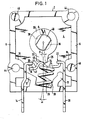
- FIGS. 1 and 4 The same reference numerals in the individual drawings designate the same parts.
- the switch has a substantially cuboid housing 2 with a housing base 4 and vertically upwardly projecting side walls 6.
- a cylindrical bearing pin 8 projects vertically upward from the housing base 4, but not up to the height of the upper edge of the side walls 6. From the two side walls 6 project mutually opposite projections 10 into the interior of the switch housing.
- approximately L-shaped webs 12 protrude from the wall of the housing adjacent to the two side walls 6, so that one leg of these webs 12 is at a distance from each of the projections 10.
- An intermediate space is thus present between the respective projection 10 and the associated web 12, in which a contact tab 14 or a solder tab 20 is clamped.
- the lower housing wall has 2 grooves for receiving the contact tab 14 or the solder tab 20.
- a projection also projects upward from the housing base 4, which protrudes into a corresponding recess on the underside of the contact lug 14 or the soldering lug 20 protrudes and thus also holds these two flags in their axial direction.
- the two flags are secured against falling out by a housing closing plate 50 (FIG. 3).
- a contact bracket 18 is held on the solder tab 20 via a cutting edge bearing 22.
- the contact clip 18 extends from the soldering tab 20 holding it to the contact tab 14, which is bent in an L-shape at its end located in the housing and has a contact 16 on the side opposite the end of the contact clip 18, for example in the form of a pressed-in spherical cap.
- the contact bracket 18 has an arc 40 pointing in the direction of the bearing journal 8, which opens out via its side flanks (41) into the essentially straight-line parts of the contact bracket.
- the contact bracket 18 has a taper 24, which serves to center a spring 26, which is designed here as a helical spring.
- This spring 26 is held in a guide 28 which is formed by the two webs 12.
- the central axis of the spring is inclined at an angle ⁇ with respect to a line which connects the base point of the spring with the center of the pivot.
- the angle ⁇ is here. an acute angle, the spring being inclined so that a force component presses the contact clip 18 in the direction of the solder tab 20. However, the main force component presses the contact bracket 18 in the direction of the bearing pin 8.
- a cam part 30 is rotatably mounted on the journal 8.
- the cam part 30 has a cam projection 32, the radially outward-facing side of which has a radius of curvature which is essentially the radius from the center of the journal 8 to the radially outer side Side of the cam projection 32 corresponds.
- On one side of the cam projection 32 there is a nose 34 which projects radially outwards and has a relatively small radius of curvature. The nose opens on one side into a steep side flank 35 of the cam projection and on its other side into the radially outer side of the cam projection 32.
- the cam part 30 has a circular, central bore 38 which is adapted to the diameter of the bearing pin 8. However, this bore does not go completely through the cam part 30. Rather, this bore opens into a recess 36, which allows a positive connection with a drive pin 48. In the exemplary embodiment shown, this recess has two rectilinear walls which run parallel and opposite one another and which run as a secant to the circle of the bore 38.
- a bearing play is provided between the drive pin 48 and the recess 36, which allows the cam part 30 to be pivoted by the angle ⁇ when the drive pin is held in place.
- This angle ⁇ corresponds approximately to the width of the nose 34, measured as an angle from the center of the bearing pin 8.
- the housing 2 also has fastening bores 44 and 46, of which the bores 44 are through bores and, in the exemplary embodiment shown, the bores 46 are designed as blind bores.
- the housing wall has corresponding thickenings in the area of these bores.
- Fig. 1 the switch is open, the arch 40 of the contact bracket 18 is supported on the outside of the cam projection 32 and by the force of the Spring 26 is pressed against this.
- the cam member is rotated clockwise in Fig. 1.
- the nose 34 engages with the arc and presses the contact clip downward a little.
- the radially outermost part of the nose 34 has reached the apex of the arc 40, the downward movement of the contact bracket 18 is ended and a "dead center position" is reached.
- the cam part 30 is rotated counterclockwise until the position shown in FIG. 4 is reached, in which the two side flanks 35 and 41 come into contact with one another. In this position, these side flanks 35 and 41 are essentially in a line.
- the contact bracket 18 is pressed down by the nose 34, whereby the electrical contact is opened. Due to the steepness of the side flanks 35 and 41, rotation of the cam part 30 by a very small angular amount is sufficient to achieve the full stroke for opening the switch. Any sparks between the contacts that are opening are caused by the rapidly increasing distance quickly deleted.
- the cam part snaps back into the position shown in FIG. 1 due to the bearing play, the audible and tactile click effect again occurring.
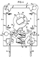
- Fig. 2 shows the switch of the invention in combination with a rotary potentiometer.
- the housing 2 of the switch is closed by a housing closing plate 50, only one opening being provided for the drive pin 48.
- This drive pin is part of a rotary shaft 58, on which grinders 56 for the rotary potentiometer are also attached.
- the rotary shaft 58 is mounted in a potentiometer housing 60.
- a shielding plate 52 is provided adjacent to the insulating plate 50, to which a resistance plate 54 of the rotary potentiometer is then attached.
- the corresponding contacts of the rotary potentiometer are accessible via soldering lugs 66, 68 and 70, which protrude in the same direction as the soldering lug 20 or the contact lug 14.
- the potentiometer '60, the resistance plate 54, the shielding plate 52, the insulating plate 50 and the switch casing 2 are interconnected via two rivets (see. The bores 44 in Fig. L). Corresponding bores of the resistance plate 54 can be seen from FIG. 3.
- a radially outwardly projecting stop 72 is attached, which comes to a stop against a corresponding counter-stop in the potentiometer housing 60 and thus defines the limit described above for the rotary movement of the switch.
- the switch can be switched on and off by rotating the rotary shaft 58 and, in addition, the rotary potentiometer can be actuated when the switch is switched on.
- This rotary potentiometer can have, for example, the resistance tracks 62 and 64 shown in FIG. 3, which are in contact with the grinders 56.
- the cutting edge bearing 22 has a self-cleaning effect between the contact bracket 18 and the soldering lug 20, which increases the functional reliability.
Abstract
Description
Die Erfindung bezieht sich auf einen elektrischen Schalter mit einem schwenkbaren Kontaktbügel, einem drehbaren Betätigungsorgan für den Kontaktbügel, einer Kontaktfahne mit der der Kontaktbügel in und außer Berührung bringbar ist und einer elektrisch mit dem Kontaktbügel verbundenen Lötfahne. Derartige Schalter sind allgemein bekannt und im Handel erhältlich. Das Betätigungsorgan ist hierbei ein Sprung- bzw. Überholglied, das bei zunehmender Bewegung des Betätigungsorgans zunächst nur über eine_Feder vorgespannt wird und dann nach Erreichen einer bestimmten Grenzstellung schlagartig in einer Richtung schnellt um den Schalter zu betätigen, d.h. zu öffnen oder zu schließen. Derartige Schalter dienen primär dazu, verhältnismäßig große elektrische Ströme zu schalten, bei denen die Gefahr der Funkenbildung und damit auch des Kontaktabbrandes besteht. Es ist daher wichtig, eine möglichst schnelle Bewegung des Schaltbügels zu erzielen, unabhängig von der Bewegungsgeschwindigkeit des Betätigungsorgans.The invention relates to an electrical switch with a pivotable contact bracket, a rotatable actuator for the contact bracket, a contact lug with which the contact bracket can be brought into and out of contact and a soldering lug electrically connected to the contact bracket. Such switches are generally known and commercially available. The actuator is a jump or overrunning element, which is initially biased only with a spring when the actuator moves and then, after reaching a certain limit position, suddenly in one direction to actuate the switch, ie to open or close it. Such switches are primarily used to switch relatively large electrical currents in which there is a risk of spark formation and thus also of contact erosion. It is therefore important to achieve the fastest possible movement of the control bracket, regardless of the speed of movement of the actuator.
Die bekannten Schalter mit Sprung- bzw. Überholglied weisen jedoch eine Reihe von Nachteilen auf. So ist nicht gewährleistet, daß durch einen Lichtbogen miteinander verschweißte Kontakte wieder geöffnet werden können, da die Kraft für die Betätigung des Schaltbügels von der Stärke der Feder bestimmt ist. Auch sind diese Schalter mechanisch verhältnismäßig aufwendig, kompliziert zu montieren und daher teuer in der Herstellung.However, the known switches with jump or overtaking element have a number of disadvantages. This does not guarantee that contacts welded together by an arc can be opened again, since the force for actuating the switching bracket is determined by the strength of the spring. These switches are mechanically relatively complex, complicated to assemble and therefore expensive to manufacture.
Mit der Erfindung sollen diese Nachteile beseitigt werden. Aufgabe der Erfindung ist es daher, den elektrischen Schalter der eingangs genannten Art dahingehend zu verbessern, daß mit einfachen Mitteln stets eine schnelle Schaltbewegung des Kontaktbügels erzielt wird und eventuell miteinander verschweißte Kontakte sicher getrennt werden.These disadvantages are to be eliminated with the invention. The object of the invention is therefore to improve the electrical switch of the type mentioned in such a way that a quick switching movement of the contact bracket is always achieved with simple means and possibly welded contacts are safely separated.
Diese Aufgabe wird erfindungsgemäß dadurch gelöst, daß das Betätigungsorgan ein Nockenteil ist, das einen Nockenvorsprung und eine hieran angebrachte, radial nach außen vorspringenden Nase mit steiler Seitenflanke aufweist, daß der Kontaktbügel einen in Richtung auf das Nockenteil hin weisenden Bogen aufweist und daß der Kontaktbügel durch eine Feder in Richtung auf das Nockenteil vorgespannt ist.This object is achieved in that the actuator is a cam member having a cam projection and a radially outwardly projecting nose attached to it with a steep side flank, that the contact bracket has an arc pointing towards the cam member and that the contact bracket by a spring is biased towards the cam member.
Durch die steile Seitenflanke der Nase, die mit der Seitenflanke am Bogen des Kontaktbügels zusammenwirkt wird eine Drehbewegung des Nockenteiles um einen geringen Winkelbetrag in eine verhältnismäßig große Hubbewegung des Kontaktbügels übersetzt. Eventuell verschweißte Kontakte werden bei Betätigung des Nockenteils zwangsweise getrennt.Due to the steep side flank of the nose, which cooperates with the side flank on the arch of the contact bracket, a rotary movement of the cam part by a small amount of angle into a relatively large stroke movement of the Contact bracket translated. Any welded contacts are forcibly separated when the cam part is actuated.
Vorzugsweise ist die Steilheit der Seitenflanke der Nase dergestalt, daß.in der Drehstellung des Nockenteils, bei der eine erste Berührung zwischen der Seitenflanke der Nase und einer Vorderflanke des Bogens des Kontaktbügels auftritt, die Vorderflanke des Bogens des Kontaktbügels und die Seitenflanke der Nase im wesentlichen in einer Linie liegen. Hierdurch wird eine besonders große "Übersetzung" der Drehbewegung des Nockenteils in eine Schwenkbewegung des Kontaktbügels erreicht. Nach einer vorteilhaften Weiterbildung der Erfindung ist zwischen einem formschlüssig mit dem Nockenteil verbundenen Antriebszapfen und einer entsprechenden Ausnehmung des Nockenteils in Drehrichtung ein Lagerspiel vorhanden. Durch dieses Lagerspiel wird erreicht, daß das Nockenteil weiter springt, wenn die Nase einen Totpunkt am Bogen des Kontaktbügels erreicht hat, unabhängig von einer weiteren Drehung des Antriebszapfens. Hierdurch wird ein sprunghaftes Schließen des Kontaktes erreicht, wodurch auch ein hör- und fühlbarer "Klickeffekt" entsteht. Die für diese Bewegung des Nockenteils erforderliche Kraft wird durch die Feder und das Zusammenwirken der Flanken der Nase und des Bogens erzeugt. Im eingeschalteten Zustand ist der Kontaktbügel in Ruhestellung und das Nockenteil liegt nicht an dem Kontaktbügel an, so daß keine Reibungskräfte in weiteren Anbauelementen durch den Schalter verursacht werden. Auch Abbrand hat somit keinen Einfluß auf die Funktion des Schalters.Preferably, the steepness of the side flank of the nose is such that, in the rotational position of the cam part, in which a first contact occurs between the side flank of the nose and a front flank of the bow of the contact bracket, the front flank of the bow of the contact bow and the side flank of the nose are essentially lie in a line. As a result, a particularly large "translation" of the rotary movement of the cam part into a pivoting movement of the contact clip is achieved. According to an advantageous development of the invention, a bearing clearance is present between a drive pin which is positively connected to the cam part and a corresponding recess in the cam part in the direction of rotation. This bearing play ensures that the cam part jumps further when the nose has reached a dead center on the arc of the contact bracket, regardless of a further rotation of the drive pin. As a result, the contact is suddenly closed, which also results in an audible and tactile “click effect”. The force required for this movement of the cam part is generated by the spring and the interaction of the flanks of the nose and the bow. In the switched-on state, the contact bracket is in the rest position and the cam part is not in contact with the contact bracket, so that no frictional forces are caused by the switch in further attachment elements. Burn-up also has no influence on the function of the switch.
Vorzugsweise ist das erwähnte Lagerspiel mindestens so groß, daß das Nockenteil gegenüber dem Antriebszapfen um einen solchen Winkelbetrag drehbar ist, daß das Nockenteil von einer Totpunktstellung in eine stabile Lage drehen kann. Dieser Winkelbetrag entspricht vorzugsweise etwa der Breite der Nase, gemessen als Winkel ausgehend vom Drehpunkt des Nockenteils. Dieser Winkelbetrag beträgt etwa 3 - 5°.Preferably, the mentioned bearing play is at least so large that the cam part can be rotated relative to the drive pin by such an angular amount that the cam part can rotate from a dead center position to a stable position. This angular amount preferably corresponds approximately the width of the nose, measured as an angle from the pivot point of the cam part. This angular amount is about 3 - 5 °.
Nach einer Weiterbildung der Erfindung ist die den Kontaktbügel in Richtung auf das Nockenteil vorspannende Feder so eingebaut, daß ihre Wirkrichtung gegenüber einer vom Drehpunkt des Nockenteils zum Fußpunkt der Feder verlaufenden Linie einen spitzen Winkel bildet. Hierdurch wird erreicht, daß ein Lagerspiel in dem Schwenklager zwischen dem Kontaktbügel und der diesen tragenden Lötfahne keinen Einfluß auf den Schaltvorgang hat, da der Kontaktbügel stets in eine Endstellung des Schwenklagers gedrückt ist.According to a development of the invention, the spring biasing the contact clip in the direction of the cam part is installed in such a way that its direction of action forms an acute angle with respect to a line running from the pivot point of the cam part to the base point of the spring. This ensures that a bearing play in the swivel bearing between the contact bracket and the soldering lug carrying it has no influence on the switching process, since the contact bracket is always pressed into an end position of the swivel bearing.
Vorzugsweise ist die Einbaulage der Feder so, daß eine Kraftkomponente den Kontaktbügel in Richtung auf die den Kontaktbügel haltenden Lötfahne drückt. Hierdurch wird sichergestellt, daß der Kontaktbügel nicht zufällig aus dem Schneidenlager springen kann.The installation position of the spring is preferably such that a force component presses the contact clip in the direction of the soldering lug holding the contact clip. This ensures that the contact clip cannot accidentally jump out of the cutting edge bearing.
Vorzugsweise sind das Nockenteil, der Nockenvorsprung und die Nase aus einem Teil hergestellt und zwar vorzugsweise aus hartem Kunststoff. Hierdurch wird Verschleiß verhindert. Bei einem Prüfmuster des erfindungsgemäßen Schalters wurde nach 25 000 Betätigungen noch kein die einwandfreie Funktion beeinträchtigender Verschleiß festgestellt. Bei diesen Versuchen wurden Einschaltströme von 50 A bei einer Prüfspannung von 30 V durchgeführt, wobei nach 25 000 Schaltungen der Übergangswiderstand kleiner als 80 mJlwar.Preferably, the cam part, the cam projection and the nose are made from one part, preferably from hard plastic. This prevents wear. In a test sample of the switch according to the invention, after 25,000 operations, no wear impairing the proper function was found. In these tests, inrush currents of 50 A were carried out at a test voltage of 30 V, the contact resistance being less than 80 mJl after 25,000 switching operations.
Vorzugsweise ist vorgesehen, daß das Nockenteil bei geschlossenem Schalter außer Eingriff mit dem Kontaktbügel ist, wodurch bei weiterer Drehung des Antriebszapfens, beispielsweise für ein angebautes Potentiometer keine zusätzlichen Reibungskräfte durch den Schalter.verursacht werden.It is preferably provided that the cam part is out of engagement with the contact bracket when the switch is closed, so that no further frictional forces are caused by the switch when the drive pin rotates further, for example for an attached potentiometer.
Im folgenden wird die Erfindung anhand eines Ausführungsbeispieles im Zusammenhang mit der Zeichnung ausführlicher erläutert. Es zeigt:
- Fig. 1 eine Draufsicht auf den geöffneten Schalter;
- Fig. 2 eine teilweise geschnittene Seitenansicht des Schalters in Kombination mit einem Drehpotentiometer;
- Fig. 3 eine Draufsicht auf Widerstandsbahnen des Drehpotentiometers und
- Fig. 4 eine Draufsicht ähnlich Fig. l jedoch in einer anderen Drehstellung des Nockenteiles.
- Figure 1 is a plan view of the open switch.
- Figure 2 is a partially sectioned side view of the switch in combination with a rotary potentiometer.
- Fig. 3 is a plan view of resistance tracks of the rotary potentiometer and
- Fig. 4 is a plan view similar to FIG. 1 but in a different rotational position of the cam part.
Zuerst sei auf die Figuren 1 und 4 Bezug genommen. Gleiche Bezugszeichen in den einzelnen Zeichnungen bezeichnen gleiche Teile.First, reference is made to FIGS. 1 and 4. The same reference numerals in the individual drawings designate the same parts.
Der Schalter besitzt ein im wesentlichen quaderförmiges Gehäuse 2 mit einem Gehäuseboden 4 und senkrecht nach oben ragenden Seitenwänden 6. Ein zylindrischer Lagerzapfen 8 ragt senkrecht vom Gehäuseboden 4 nach oben, jedoch nicht bis zur Höhe der Oberkante der Seitenwände 6. Von den beiden Seitenwänden 6 ragen einander gegenüberliegende Vorsprünge 10 in das Innere des Schaltergehäuses hinein. Ebenso ragen in etwa L-förmige Stege 12 von der den beiden Seitenwänden 6 benachbarten Wand des Gehäuses hervor, so daß ein Schenkel dieser Stege 12 jeweils einem der Vorsprünge 10 im Abstand gegenüber liegt. Zwischen dem jeweiligen Vorsprung 10 und dem zugeordneten Steg 12 ist somit ein Zwischenraum vorhanden, in welchem eine Kontaktfahne 14 bzw. eine Lötfahne 20 festgeklemmt ist. Zusätzlich weist die untere Gehäusewand 2 Nuten zur Aufnahme der Kontaktfahne 14 bzw. der Lötfahne 20 auf. Zur Arretierung der Kontaktfahne 14 bzw. der Lötfahne 20 ragt zusätzlich vom Gehäuseboden 4 ein (nicht dargestellter) Vorsprung nach oben, der in eine entsprechende Ausnehmung an der Unterseite der Kontaktfahne 14 bzw. der Lötfahne 20 hineinragt und somit diese beiden Fahnen auch in ihrer Axialrichtung festhält. Gegen Herausfallen sind die beiden Fahnen durch eine Gehäuseschließplatte 50 (Fig. 3) gesichert. An der Lötfahne 20 ist ein Kontaktbügel 18 über ein Schneidenlager 22 gehalten. Der Kontaktbügel 18 erstrecktsich von der ihn haltenden Lötfahne 20 zu der Kontaktfahne 14, welche an ihrem im Gehäuse liegenden Ende L-förmig umgebogen ist und an der dem Ende des Kontaktbügels 18 gegenüberliegenden Seite einen Kontakt 16 aufweist, beispielsweise in Form einer eingepreßten Kugelkalotte. Durch Schwenken des Kontaktbügels 18 kann dessen dem Kontakt 16 gegenüberliegende Kontaktfläche 42 in und außer Berührung mit dem Kontakt 16 gebracht werden.The switch has a substantially cuboid housing 2 with a
Der Kontaktbügel 18 besitzt einen in Richtung zu dem Lagerzapfen 8 hin weisenden Bogen 40, der über seine Seitenflanken (41) in die im wesentlichen geradlinig verlaufenden Teile des Kontaktbügels einmündet. Zwischen dem Bogen 40 und dem Schneidenlager 22 besitzt der Kontaktbügel 18 eine Verjüngung 24, welche zur Zentrierung einer Feder 26 dient, die hier als Schraubenfeder ausgebildet ist. Diese Feder 26 ist in einer Führung 28 gehalten, welche durch die beiden Stege 12 gebildet wird. Die Mittelachse der Feder ist unter einem Winkel α gegenüber einer Linie geneigt, die den Fußpunkt der Feder mit dem Mittelpunkt des Drehzapfens verbindet. Der Winkel α ist hierbei. ein spitzer Winkel, wobei die Feder so geneigt ist, daß eine Kraftkomponente den Kontaktbügel 18 in Richtung zu der Lötfahne 20 hin drückt. Die Hauptkraftkomponente drückt jedoch den Kontaktbügel 18 in Richtung auf den Lagerzapfen 8.The
Auf dem Lagerzapfen 8 ist ein Nockenteil 30 drehbar gelagert. Das Nockenteil 30 besitzt einen Nockenvorsprung 32, dessen radial nach außen weisende Seite einen Krümmungsradius aufweist, der im wesentlichen dem Radius vom Mittelpunkt des Lagerzapfens 8 zu der radial außen liegenden Seite des Nockenvorsprunges 32 entspricht. An einer Seite des Nockenvorsprunges 32 ist eine Nase 34 angebracht, die radial nach außen vorspringt und einen verhältnismäßig kleinen Krümmungsradius hat. Die Nase mündet auf ihrer einen Seite in eine steile Seitenflanke 35 des Nockenvorsprunges und auf ihrer anderen Seite in die radial außen liegende Seite des Nockenvorsprunges 32.A
Das Nockenteil 30 besitzt eine kreisrunde, mittige Bohrung 38, die an den Durchmesser des Lagerzapfens 8 angepaßt ist. Diese Bohrung geht jedoch nicht vollständig durch das Nockenteil 30 hindurch. Vielmehr mündet diese Bohrung in eine Ausnehmung 36, die eine formschlüssige Verbindung mit einem Antriebszapfen 48 erlaubt. Im dargestellten Auslührungsbeispiel hat diese Ausnehmung zwei parallel zueinander gegenüberliegend verlaufende geradlinige Wände, die als Sekante zu dem Kreis der Bohrung 38 verlaufen.The
Zwischen dem Antriebszapfen 48 und der Ausnehmung 36 ist ein Lagerspiel vorgesehen, das bei festgehaltenem Antriebszapfen eine Schwenkung des Nockenteiles 30 um den Winkel ß erlaubt. Dieser Winkel β entspricht in etwa der Breite der Nase 34 gemessen als Winkel vom Mittelpunkt des Lagerzapfens 8.aus gesehen.A bearing play is provided between the
Schließlich weist das Gehäuse 2 noch Befestigungsbohrungen 44 bzw. 46 auf, von denen die Bohrungen 44 Durchgangsbohrungen sind und im dargestellten Ausführungsbeispiel die Bohrungen 46 als Blindbohrungen ausgelegt sind. Die Gehäusewandung weist im Bereich dieser Bohrungen entsprechende Verdickungen auf.Finally, the housing 2 also has fastening bores 44 and 46, of which the
Im folgenden sei die Wirkungsweise des Schalters erläutert. In Fig. 1 ist der Schalter geöffnet, wobei sich der Bogen 40 des Kontaktbügels 18 auf der Außenseite des Nokkenvorsprunges 32 abstützt und durch die Kraft der Feder 26 gegen diesen gedrückt wird. Zum Schließen des Schalters wird das Nockenteil in Fig. 1 im Uhrzeigersinn gedreht. Hierdurch gelangt die Nase 34 mit dem Bogen in Eingriff und drückt den Kontaktbügel noch etwas nach unten. Wenn der radial äußerste Teil der Nase 34 den Scheitelpunkt des Bogens 40 erreicht hat, so ist die Abwärtsbewegung des Kontaktbügels 18 beendet und es ist eine "Totpunktlage" erreicht. Wird nun das Nockenteil 30 geringfügig weiter im Uhrzeigersinn gedreht, so übt die nun mit der Nase 34 in Berührung kommende Vorderflanke 41 des Bogens 40 ein Drehmoment auf das Nockenteil 30 aus, welches sich dann aufgrund des Spiels zwischen Antriebszapfen 48 und Ausnehmung 36 unabhängig von einer Drehung des Antriebszapfens 48 drehen kann, bis die in Fig. 4 gezeigte Stellung erreicht ist und der Schalter geschlossen ist. Hierbei entsteht dann auch ein hör- und fühlbarer Klickeffekt. Auch wird der Schalter durch die Federkraft sehr schnell geschlossen, so daß Einschaltstromspitzen keine nennenswerten Funken und damit Verschweißungen zwischen Kontakt 16 und Kontaktfläche 42 hervorrufen können. Die Kraft der Feder 26 beträgt etwa 3 bis 4 Newton bei geschlossenem Schalter, wodurch auch ein definierter Kontaktdruck erreicht wird.The operation of the switch is explained below. In Fig. 1, the switch is open, the
Zum Öffnen des Schalters wird das Nockenteil 30 gegen den Uhrzeigersinn gedreht, bis zunächst die in Fig. 4 dargestellte Lage erreicht ist, bei der die beiden Seitenflanken 35 und 41 miteinander in Berührung kommen. In dieser Lage liegen diese Seitenflanken 35 und 41 im wesentlichen in einer Linie. Bei weiterer Drehung des Nockenteils 30 gegen den Uhrzeigersinn wird der Kontaktbügel 18 durch die Nase 34 nach unten gedrückt, wodurch der elektrische Kontakt geöffnet wird. Aufgrund der Steilheit der Seitenflanken 35 und 41 genügt eine Drehung des Nockenteils 30 um einen sehr kleinen Winkelbetrag, um den vollen Hub zum Öffnen des Schalters zu erreichen. Eventuelle Funken zwischen den sich öffnenden Kontakten werden durch den sich rasch vergrößernden Abstand schnelll gelöscht. Sobald die Nase 34 die erwähnte Totpunktstellung geringfügig überschritten hat, schnappt das Nockenteil aufgrund des Lagerspiels wieder in die in Fig. 1 gezeigte Stellung zurück, wobei wieder der hör- und fühlbare Klickeffekt auftritt.To open the switch, the
Damit das Nockenteil 30 nicht so weit gegen den Uhrzeigersinn weitergedreht werden kann, daß der Bogen 40 nicht mehr auf dem Nockenvorsprung 32 aufliegt, ist ein Drehbegrenzungsanschlag vorgesehen, der in Zusammenhang mit Fig. 2 beschrieben wird.So that the
Fig. 2 zeigt den Schalter der Erfindung in Kombination mit einem Drehpotentiometer. Das Gehäuse 2 des Schalters ist durch eine Gehäuseschließplatte 50 verschlossen, wobei lediglich eine Öffnung für den Antriebszapfen 48 vorgesehen ist. Dieser Antriebszapfen ist Bestandteil einer Drehwelle 58, an welcher auch Schleifer 56 für das Drehpotentiometer angebracht sind. Die Drehwelle 58 ist in einem Potentiometergehäuse 60 gelagert. Angrenzend an die Isolierplatte 50 ist ein Abschirmblech 52 vorgesehen, an welcher dann eine Widerstandsplatte 54 des Drehpotentiometers angebracht ist. Die entsprechenden Kontakte des Drehpotentiometers sind über Lötfahnen 66, 68 und 70 zugänglich, welche gleichsinnig zu der Lötfahne 20 bzw. der Kontaktfahne 14 herausragen. Das Potentiometergehäuse ' 60, die Widerstandsplatte 54, das Abschirmblech 52, die Isolierplatte 50 und das Schaltergehäuse 2 sind über zwei Nieten miteinander verbunden (vgl. die Bohrungen 44 in Fig. l). Aus Fig. 3 sind entsprechende Bohrungen der Widerstandsplatte 54 erkennbar.Fig. 2 shows the switch of the invention in combination with a rotary potentiometer. The housing 2 of the switch is closed by a housing closing plate 50, only one opening being provided for the
An der Drehwelle 58 ist ein radial nach außen vorspringender Anschlag 72 angebracht, der gegen einen entsprechenden Gegenanschlag im Potentiometergehäuse 60 zum Anschlag kommt und damit die oben geschilderte Begrenzung für die Drehbewegung des Schalters festlegt.On the
Durch Drehung der Drehwelle 58 kann in dem Ausführungsbeispiel der Fig. 2 der Schalter ein- und ausgeschaltet werden und zusätzlich kann bei eingeschaltetem Schalter das Drehpotentiometer betätigt werden. Dieses Drehpotentiometer kann beispielsweise die in Fig. 3 gezeigten Widerstandsbahnen 62 und 64 haben, welche mit den Schleifern 56 in Berührung stehen.In the exemplary embodiment in FIG. 2, the switch can be switched on and off by rotating the
Abschließend sei noch erwähnt, daß das Schneidenlager 22 zwischen dem Kontaktbügel 18 und der Lötfahne 20 eine selbstreinigende Wirkung hat, was die Funktionssicherheit erhöht.Finally, it should also be mentioned that the cutting edge bearing 22 has a self-cleaning effect between the
Sämtliche in den Patentansprüchen, der Beschreibung und der Zeichnung dargestellten technischen Einzelheiten können sowohl für sich als auch in beliebiger Kombination miteinander erfindungswesentlich sein.All of the technical details shown in the claims, the description and the drawing can be essential to the invention both individually and in any combination with one another.
Claims (10)
Applications Claiming Priority (2)
| Application Number | Priority Date | Filing Date | Title |
|---|---|---|---|
| DE3243323A DE3243323C2 (en) | 1982-11-23 | 1982-11-23 | Electric switch |
| DE3243323 | 1982-11-23 |
Publications (2)
| Publication Number | Publication Date |
|---|---|
| EP0110149A1 true EP0110149A1 (en) | 1984-06-13 |
| EP0110149B1 EP0110149B1 (en) | 1986-01-29 |
Family
ID=6178824
Family Applications (1)
| Application Number | Title | Priority Date | Filing Date |
|---|---|---|---|
| EP83110767A Expired EP0110149B1 (en) | 1982-11-23 | 1983-10-27 | Electrical switch |
Country Status (4)
| Country | Link |
|---|---|
| EP (1) | EP0110149B1 (en) |
| DE (2) | DE3243323C2 (en) |
| ES (1) | ES285289Y (en) |
| YU (1) | YU44756B (en) |
Cited By (1)
| Publication number | Priority date | Publication date | Assignee | Title |
|---|---|---|---|---|
| ITTO20100019A1 (en) * | 2010-01-15 | 2011-07-16 | Comparato Nello S R L Sistemi Idrotermici | COUPLING BETWEEN CAM AND OUTPUT SHAFT OF A GEARED GEARED MOTOR TO CHECK THE OPENING AND CLOSING OF VALVES IN HYDRAULIC AND / OR HYDROTHERMIC PLANTS |
Families Citing this family (3)
| Publication number | Priority date | Publication date | Assignee | Title |
|---|---|---|---|---|
| DE4233520C1 (en) * | 1992-10-06 | 1994-06-01 | Teves Gmbh Alfred | Electrical rotary switch particularly for use as ignition switch in vehicles - has centre spindle with cam elements that displace movable contact carriers located around periphery |
| DE4237753C1 (en) * | 1992-11-09 | 1994-05-26 | Teves Gmbh Alfred | Rotary switch for vehicle ignition or starter-switch - has flat connections offset from each other in base-plate by distances which allow unhampered cable exit |
| DE4330310A1 (en) * | 1993-09-08 | 1995-03-09 | Teves Gmbh Alfred | Rotary switch with sliding contact being made on sliding contacts which are domed in a cylindrical shape |
Citations (6)
| Publication number | Priority date | Publication date | Assignee | Title |
|---|---|---|---|---|
| AT165780B (en) * | ||||
| DE972755C (en) * | 1952-11-13 | 1959-09-17 | Stotz Kontakt Gmbh | Electric cam switches, the contact levers of which are controlled radially to the switching axis by cam disks consisting of a press body unit |
| US3497643A (en) * | 1967-05-12 | 1970-02-24 | United Carr Inc | Rotary switch |
| DE7421243U (en) * | 1974-06-21 | 1975-04-03 | Ruf W Kg | Single pole switch |
| FR2341192A1 (en) * | 1976-02-16 | 1977-09-09 | Seima | Motor vehicle lighting control - is steering column mounted with movement to control headlight beam, trafficators and main light on-off switch |
| US4103132A (en) * | 1976-10-05 | 1978-07-25 | Unimax Switch Corporation | Rotary switch |
Family Cites Families (5)
| Publication number | Priority date | Publication date | Assignee | Title |
|---|---|---|---|---|
| DE1050862B (en) * | ||||
| DE1218040B (en) * | 1964-07-08 | 1966-06-02 | Busch Jaeger Duerener Metall | Electric pull switch |
| FR1516928A (en) * | 1967-01-16 | 1968-02-05 | Improvements to potentiometer switches | |
| DE2451034C3 (en) * | 1974-10-26 | 1980-08-14 | J. & J. Marquardt, 7201 Rietheim | Electric switch |
| DE2832921C2 (en) * | 1978-07-27 | 1981-10-08 | Preh, Elektrofeinmechanische Werke, Jakob Preh, Nachf. Gmbh & Co, 8740 Bad Neustadt | Electric switch |
-
1982
- 1982-11-23 DE DE3243323A patent/DE3243323C2/en not_active Expired
-
1983
- 1983-10-27 EP EP83110767A patent/EP0110149B1/en not_active Expired
- 1983-10-27 DE DE8383110767T patent/DE3362039D1/en not_active Expired
- 1983-11-22 YU YU2287/83A patent/YU44756B/en unknown
- 1983-11-23 ES ES285289U patent/ES285289Y/en not_active Expired
Patent Citations (6)
| Publication number | Priority date | Publication date | Assignee | Title |
|---|---|---|---|---|
| AT165780B (en) * | ||||
| DE972755C (en) * | 1952-11-13 | 1959-09-17 | Stotz Kontakt Gmbh | Electric cam switches, the contact levers of which are controlled radially to the switching axis by cam disks consisting of a press body unit |
| US3497643A (en) * | 1967-05-12 | 1970-02-24 | United Carr Inc | Rotary switch |
| DE7421243U (en) * | 1974-06-21 | 1975-04-03 | Ruf W Kg | Single pole switch |
| FR2341192A1 (en) * | 1976-02-16 | 1977-09-09 | Seima | Motor vehicle lighting control - is steering column mounted with movement to control headlight beam, trafficators and main light on-off switch |
| US4103132A (en) * | 1976-10-05 | 1978-07-25 | Unimax Switch Corporation | Rotary switch |
Cited By (1)
| Publication number | Priority date | Publication date | Assignee | Title |
|---|---|---|---|---|
| ITTO20100019A1 (en) * | 2010-01-15 | 2011-07-16 | Comparato Nello S R L Sistemi Idrotermici | COUPLING BETWEEN CAM AND OUTPUT SHAFT OF A GEARED GEARED MOTOR TO CHECK THE OPENING AND CLOSING OF VALVES IN HYDRAULIC AND / OR HYDROTHERMIC PLANTS |
Also Published As
| Publication number | Publication date |
|---|---|
| EP0110149B1 (en) | 1986-01-29 |
| DE3362039D1 (en) | 1986-03-13 |
| DE3243323A1 (en) | 1984-05-24 |
| ES285289Y (en) | 1988-07-01 |
| DE3243323C2 (en) | 1985-03-07 |
| YU228783A (en) | 1986-02-28 |
| YU44756B (en) | 1991-02-28 |
| ES285289U (en) | 1985-09-01 |
Similar Documents
| Publication | Publication Date | Title |
|---|---|---|
| EP1399673B1 (en) | Wind turbine with switchgear comprising an actuating shaft | |
| DE10222667A1 (en) | switchgear | |
| DE2505603A1 (en) | ELECTRIC SWITCH | |
| DE3731079A1 (en) | ELECTRIC HAND TOOL WITH A UNIVERSAL MOTOR WITH RIGHT AND LEFT ROTATION | |
| EP0482191B1 (en) | Screw-on terminal | |
| EP0222181A1 (en) | Overcurrent circuit breaker | |
| EP0110149A1 (en) | Electrical switch | |
| DE2505894C3 (en) | Electric key switch | |
| EP0584587B1 (en) | Fuse switch with voltage interruption on both sides | |
| DE1665063A1 (en) | Electric switch | |
| DE2536603C3 (en) | Electric switch | |
| CH670170A5 (en) | ||
| EP0502394B1 (en) | Contact configuration | |
| DE3013985C2 (en) | ||
| EP0565008B1 (en) | Test button device for an earth fault circuit breaker or a differential current circuit breaker | |
| EP0158241B1 (en) | Electrical switch | |
| DE3210033C2 (en) | ||
| EP0543124A2 (en) | Electrical switch | |
| DE4121571C2 (en) | Electrical switch | |
| EP0399419A2 (en) | Electric snap-action switch particularly micro switch | |
| DE10326396B3 (en) | Electric door opener with adjustable latch and cooperating lever for operation of microswitch when door is closed | |
| DE2558620C2 (en) | Electric switch | |
| DE3824145C1 (en) | Steering-column switch on motor vehicles for indicating the direction of travel | |
| EP0071207A2 (en) | Electric rotary switch with a positioning shaft actuated by rotation and sliding movement along the axis by an operating part | |
| DE4328030C2 (en) | Electric rotary switch |
Legal Events
| Date | Code | Title | Description |
|---|---|---|---|
| PUAI | Public reference made under article 153(3) epc to a published international application that has entered the european phase |
Free format text: ORIGINAL CODE: 0009012 |
|
| AK | Designated contracting states |
Designated state(s): DE FR GB IT |
|
| 17P | Request for examination filed |
Effective date: 19840507 |
|
| ITF | It: translation for a ep patent filed |
Owner name: DR. ING. A. RACHELI & C. |
|
| GRAA | (expected) grant |
Free format text: ORIGINAL CODE: 0009210 |
|
| AK | Designated contracting states |
Designated state(s): DE FR GB IT |
|
| REF | Corresponds to: |
Ref document number: 3362039 Country of ref document: DE Date of ref document: 19860313 |
|
| ET | Fr: translation filed | ||
| PLBE | No opposition filed within time limit |
Free format text: ORIGINAL CODE: 0009261 |
|
| STAA | Information on the status of an ep patent application or granted ep patent |
Free format text: STATUS: NO OPPOSITION FILED WITHIN TIME LIMIT |
|
| 26N | No opposition filed | ||
| ITTA | It: last paid annual fee | ||
| PGFP | Annual fee paid to national office [announced via postgrant information from national office to epo] |
Ref country code: GB Payment date: 19920922 Year of fee payment: 10 Ref country code: FR Payment date: 19920922 Year of fee payment: 10 |
|
| PGFP | Annual fee paid to national office [announced via postgrant information from national office to epo] |
Ref country code: DE Payment date: 19921029 Year of fee payment: 10 |
|
| PG25 | Lapsed in a contracting state [announced via postgrant information from national office to epo] |
Ref country code: GB Effective date: 19931027 |
|
| GBPC | Gb: european patent ceased through non-payment of renewal fee |
Effective date: 19931027 |
|
| PG25 | Lapsed in a contracting state [announced via postgrant information from national office to epo] |
Ref country code: FR Effective date: 19940630 |
|
| PG25 | Lapsed in a contracting state [announced via postgrant information from national office to epo] |
Ref country code: DE Effective date: 19940701 |
|
| REG | Reference to a national code |
Ref country code: FR Ref legal event code: ST |