EP0109952A2 - Cable jacket - Google Patents
Cable jacket Download PDFInfo
- Publication number
- EP0109952A2 EP0109952A2 EP83850303A EP83850303A EP0109952A2 EP 0109952 A2 EP0109952 A2 EP 0109952A2 EP 83850303 A EP83850303 A EP 83850303A EP 83850303 A EP83850303 A EP 83850303A EP 0109952 A2 EP0109952 A2 EP 0109952A2
- Authority
- EP
- European Patent Office
- Prior art keywords
- jacket
- cable
- rubber
- cord
- layer
- Prior art date
- Legal status (The legal status is an assumption and is not a legal conclusion. Google has not performed a legal analysis and makes no representation as to the accuracy of the status listed.)
- Granted
Links
Images
Classifications
-
- H—ELECTRICITY
- H01—ELECTRIC ELEMENTS
- H01B—CABLES; CONDUCTORS; INSULATORS; SELECTION OF MATERIALS FOR THEIR CONDUCTIVE, INSULATING OR DIELECTRIC PROPERTIES
- H01B9/00—Power cables
- H01B9/001—Power supply cables for the electrodes of electric-welding apparatus or electric-arc furnaces
-
- H—ELECTRICITY
- H01—ELECTRIC ELEMENTS
- H01B—CABLES; CONDUCTORS; INSULATORS; SELECTION OF MATERIALS FOR THEIR CONDUCTIVE, INSULATING OR DIELECTRIC PROPERTIES
- H01B7/00—Insulated conductors or cables characterised by their form
- H01B7/17—Protection against damage caused by external factors, e.g. sheaths or armouring
- H01B7/18—Protection against damage caused by wear, mechanical force or pressure; Sheaths; Armouring
- H01B7/182—Protection against damage caused by wear, mechanical force or pressure; Sheaths; Armouring comprising synthetic filaments
Definitions
- the present invention relates to a cable jacket, especially a rubber jacket, to an electric welding cable and is designed to enclose groups of electrical conductors and coolant ducts for conducting pressurized medium for cooling the cable.
- the welding cable In modern automatic welding machines such as robot- type welders in which the length of the welding cable is often very short, the welding cable must be quite flexible both transversely to the longitudinal direction of the cable and about the central axis, i.e. it must be both easily bendable and twistable. Furthermore, such cables must be able to absorb the pressure stresses which are applied to the cable jacket from the inside by the pressurized coolant, and by the repelling radial forces generated by the cable cores every time the current through the cable is turned on or off.
- the primary purpose of the present invention is therefore to achieve a cable jacket which, even with very short lengths, is sufficiently flexible with regard to both bending and torsion, and is capable of absorbing the circumferential tensile forces in the jacket arising due to the pressure exerted by the coolant in the cable and the repelling radial forces generated by the cable cores every time the current through the cable is turned on or off.
- the cable jacket described by way of introduction is characterized, according to the invention, in that at least one surrounding reinforcement layer of warp-knit type known per se is vulcanized into the rubber jacket, and that radially outside said layer there are vulcanized one or more unidirectionally, helically wound reinforcing cords, the spacing between the adjacent cord windings measuring in the longitudinal direction of the jacket about 2-8 mm, preferably about 4 mm.
- each reinforcing cord consists of a slightly twined polyester string. It is also suitable that the layers of warp-knit reinforcement and reinforcing cords be separated radially by an intermediate rubber layer.
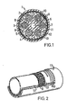
- Fig. 1 shows according to scale a cross section of a welding cable 1, which has an outer cable jacket 2 of rubber in accordance with the present invention.
- the jacket 2 encloses a group of electrical conductors in the form of copper cores 3 and 4 of different polarity, the cores being placed in a ring and separated circumferentially by rib- like walls 5 which project radially out from a central body 6 of rubber or PVC.
- the central body 6 has a central coolant duct 7 and defines, between its outside and the inside of the outer jacket 2, additional flow ducts 8 for a pressurized coolant, e.g. water.
- the jacket 2 comprises two reinforcement layers 9 of a warp-knit fabric which is known per se and a cord helix 10 lying outside said two layers.
- Warp-knit fabric refers in this context to a textile construction in which yarns, usually filament yarns, are interlooped by knitting, with the yarn threads running essentially in the longitudinal direction of the fabric.
- Fig. 2 shows more clearly the structure of a jacket according to the invention, which only shows one layer of warp-knit reinforcement 9.
- the jacket 2 has a rubber layer 11, a warp-knit reinforcement 9, a thin layer 12 of rubber, a helically wound layer 10 e.g. of lightly twined polyester, and an outer layer 13 of rubber.
- a plurality of cords 10 are used that they run parallel to each other and be wound in the same direction, i.e. not crossing each other.
- the cords should be wound leaving a gap of about 2-8 mm, preferably about 4 mm, between adjacent cord windings.
- a cable jacket according to the invention is made preferably in finite lengths by being built up on a mandrel, with one or two layers of warp-knit fabric being applied around the inner rubber layer 11. If there is more than one layer, a thin layer of rubber should be placed between the layers, and a thin layer 12 outside the outer warp knit layer 9.
- a single cord 10 of previously described type is then wound around the layer 12 helically with a pitch so that the distance between the adjacent windings of the cord will be about 2-8 mm, preferably about 4 mm, at a normal jacket diameter of about 5-6 cm.
Abstract
Description
- The present invention relates to a cable jacket, especially a rubber jacket, to an electric welding cable and is designed to enclose groups of electrical conductors and coolant ducts for conducting pressurized medium for cooling the cable.
- In modern automatic welding machines such as robot- type welders in which the length of the welding cable is often very short, the welding cable must be quite flexible both transversely to the longitudinal direction of the cable and about the central axis, i.e. it must be both easily bendable and twistable. Furthermore, such cables must be able to absorb the pressure stresses which are applied to the cable jacket from the inside by the pressurized coolant, and by the repelling radial forces generated by the cable cores every time the current through the cable is turned on or off.
- The previously known welding cable jackets have not been able to fulfill all of these requirements. Rather, the short cable lengths in question have been so rigid that they have hampered the movement of the welding robot and have resulted in fatigue failures at the bending points of the cable.
- The primary purpose of the present invention is therefore to achieve a cable jacket which, even with very short lengths, is sufficiently flexible with regard to both bending and torsion, and is capable of absorbing the circumferential tensile forces in the jacket arising due to the pressure exerted by the coolant in the cable and the repelling radial forces generated by the cable cores every time the current through the cable is turned on or off. To achieve this, the cable jacket described by way of introduction is characterized, according to the invention, in that at least one surrounding reinforcement layer of warp-knit type known per se is vulcanized into the rubber jacket, and that radially outside said layer there are vulcanized one or more unidirectionally, helically wound reinforcing cords, the spacing between the adjacent cord windings measuring in the longitudinal direction of the jacket about 2-8 mm, preferably about 4 mm. To prevent the jacket with the warp-knit reinforcement from expanding too much due to inner pressure and in order to provide good torsional properties at the same time, it is thus necessary that the reinforcing cord(s) be helically wound in the same direction and preferably lie in a single common cylinder radially outside the warp-knit layer in the jacket. Suitably, each reinforcing cord consists of a slightly twined polyester string. It is also suitable that the layers of warp-knit reinforcement and reinforcing cords be separated radially by an intermediate rubber layer.
- The invention will be described below in mpre detail with reference to the accompanying drawing.
- Fig. 1 is a cross-sectional view of a welding cable with a jacket according to the present invention, and
- Fig. 2 is a cut-away perspective view showing the various layers in a cable jacket according to the invention.
- Fig. 1 shows according to scale a cross section of a welding cable 1, which has an outer cable jacket 2 of rubber in accordance with the present invention. The jacket 2 encloses a group of electrical conductors in the form of
copper cores 3 and 4 of different polarity, the cores being placed in a ring and separated circumferentially by rib-like walls 5 which project radially out from acentral body 6 of rubber or PVC. Thecentral body 6 has acentral coolant duct 7 and defines, between its outside and the inside of the outer jacket 2,additional flow ducts 8 for a pressurized coolant, e.g. water. - As indicated in Fig. 1, the jacket 2 comprises two reinforcement layers 9 of a warp-knit fabric which is known per se and a
cord helix 10 lying outside said two layers. Warp-knit fabric refers in this context to a textile construction in which yarns, usually filament yarns, are interlooped by knitting, with the yarn threads running essentially in the longitudinal direction of the fabric. - Fig. 2 shows more clearly the structure of a jacket according to the invention, which only shows one layer of warp-knit reinforcement 9. Starting from the inside, the jacket 2 has a
rubber layer 11, a warp-knit reinforcement 9, athin layer 12 of rubber, a helicallywound layer 10 e.g. of lightly twined polyester, and anouter layer 13 of rubber. In order to obtain the desired flexibility both for bending and torsion, as well as form strength, since the jacket is subjected to high inner pressure by the coolant and radial repellant forces generated by the cable cores whenever the current through the cable is turned on or off, it is essential that if a plurality ofcords 10 are used that they run parallel to each other and be wound in the same direction, i.e. not crossing each other. The cords should be wound leaving a gap of about 2-8 mm, preferably about 4 mm, between adjacent cord windings. - A cable jacket according to the invention is made preferably in finite lengths by being built up on a mandrel, with one or two layers of warp-knit fabric being applied around the
inner rubber layer 11. If there is more than one layer, a thin layer of rubber should be placed between the layers, and athin layer 12 outside the outer warp knit layer 9. Preferably asingle cord 10 of previously described type is then wound around thelayer 12 helically with a pitch so that the distance between the adjacent windings of the cord will be about 2-8 mm, preferably about 4 mm, at a normal jacket diameter of about 5-6 cm. Although a single cord is preferable, two or even more cords can be wound parallel in the same winding direction, maintaining said distance between the cord windings, but this sacrifices some of the good torsional properties of the jacket. Anouter layer 13 of rubber is then applied outside the cord layer, and the components of the jacket are then vulcanized together into an integrated unit. The outside of the jacket is then given such a structure that its friction against a surface is reduced to the required level.
Claims (4)
Applications Claiming Priority (2)
| Application Number | Priority Date | Filing Date | Title |
|---|---|---|---|
| SE8206551A SE450674B (en) | 1982-11-17 | 1982-11-17 | cable cover |
| SE8206551 | 1982-11-17 |
Publications (3)
| Publication Number | Publication Date |
|---|---|
| EP0109952A2 true EP0109952A2 (en) | 1984-05-30 |
| EP0109952A3 EP0109952A3 (en) | 1984-07-04 |
| EP0109952B1 EP0109952B1 (en) | 1986-10-01 |
Family
ID=20348631
Family Applications (1)
| Application Number | Title | Priority Date | Filing Date |
|---|---|---|---|
| EP19830850303 Expired EP0109952B1 (en) | 1982-11-17 | 1983-11-10 | Cable jacket |
Country Status (6)
| Country | Link |
|---|---|
| EP (1) | EP0109952B1 (en) |
| JP (1) | JPS59103208A (en) |
| CA (1) | CA1204182A (en) |
| DE (1) | DE3366628D1 (en) |
| ES (1) | ES285013Y (en) |
| SE (1) | SE450674B (en) |
Families Citing this family (2)
| Publication number | Priority date | Publication date | Assignee | Title |
|---|---|---|---|---|
| ATE409495T1 (en) | 2001-04-04 | 2008-10-15 | Nordic Vaccine Technology As | POLYNUCLEOTIDE BINDING COMPLEXES THAT CONTAIN STEROLS AND SAPONINS |
| CN107622844A (en) * | 2017-09-24 | 2018-01-23 | 肇庆市高新区晓靖科技有限公司 | A kind of electric sleeve pipe of multilayer |
Citations (4)
| Publication number | Priority date | Publication date | Assignee | Title |
|---|---|---|---|---|
| US2157377A (en) * | 1937-01-21 | 1939-05-09 | Phelps Dodge Copper Prod | Electric cable |
| US2652093A (en) * | 1949-03-02 | 1953-09-15 | Gates Rubber Co | Method of making reinforced rubber hose |
| GB1170335A (en) * | 1966-03-24 | 1969-11-12 | Dayco Corp | Improvements in and relating to Flexible Hose |
| US3578028A (en) * | 1969-07-16 | 1971-05-11 | Fred T Roberts & Co | Reinforced hose and method of making the same |
-
1982
- 1982-11-17 SE SE8206551A patent/SE450674B/en not_active IP Right Cessation
-
1983
- 1983-11-10 DE DE8383850303T patent/DE3366628D1/en not_active Expired
- 1983-11-10 EP EP19830850303 patent/EP0109952B1/en not_active Expired
- 1983-11-10 CA CA000440970A patent/CA1204182A/en not_active Expired
- 1983-11-16 ES ES1983285013U patent/ES285013Y/en not_active Expired
- 1983-11-17 JP JP21705283A patent/JPS59103208A/en active Pending
Patent Citations (4)
| Publication number | Priority date | Publication date | Assignee | Title |
|---|---|---|---|---|
| US2157377A (en) * | 1937-01-21 | 1939-05-09 | Phelps Dodge Copper Prod | Electric cable |
| US2652093A (en) * | 1949-03-02 | 1953-09-15 | Gates Rubber Co | Method of making reinforced rubber hose |
| GB1170335A (en) * | 1966-03-24 | 1969-11-12 | Dayco Corp | Improvements in and relating to Flexible Hose |
| US3578028A (en) * | 1969-07-16 | 1971-05-11 | Fred T Roberts & Co | Reinforced hose and method of making the same |
Also Published As
| Publication number | Publication date |
|---|---|
| CA1204182A (en) | 1986-05-06 |
| EP0109952A3 (en) | 1984-07-04 |
| DE3366628D1 (en) | 1986-11-06 |
| SE8206551L (en) | 1984-05-18 |
| JPS59103208A (en) | 1984-06-14 |
| ES285013U (en) | 1985-06-16 |
| SE8206551D0 (en) | 1982-11-17 |
| ES285013Y (en) | 1986-04-01 |
| EP0109952B1 (en) | 1986-10-01 |
| SE450674B (en) | 1987-07-13 |
Similar Documents
| Publication | Publication Date | Title |
|---|---|---|
| US4241763A (en) | Rubber hose with spiral fiber reinforcing core | |
| US3823253A (en) | Stretchable cable | |
| US4915762A (en) | Process for making a high-pressure hose | |
| KR970006201B1 (en) | Optical fiber cable unit for underwater | |
| US4657342A (en) | Flexible power cable with profiled core and support member | |
| EP1691378B1 (en) | Deep water signal cable | |
| FI78570C (en) | OPTISK FIBER FOER ELECTRIC CABLE. | |
| JPH03502497A (en) | integrated optical cable | |
| KR101978699B1 (en) | Cable provided with braided shield | |
| KR100492957B1 (en) | Loose Tube Optical Cable | |
| JPH07117633B2 (en) | Fiber optic cable | |
| BRPI0621687A2 (en) | cable, process for making a cable, and use of fibrils | |
| JPH0137722B2 (en) | ||
| EP0476438A2 (en) | Electro-optical overhead line having 24 and more waveguides | |
| US4499926A (en) | Cable jacket | |
| EP0109952A2 (en) | Cable jacket | |
| KR20190062105A (en) | Cable provided with braided shield | |
| GB2035599A (en) | Electric power cables incorporating optical transmission elements | |
| US3230979A (en) | High strength flexible conduit | |
| GB2105484A (en) | Optical fibre cables | |
| US3446248A (en) | Reinforced hose | |
| US2128547A (en) | Multiple conductor wire rope | |
| JP2022517880A (en) | Power cables, how they are manufactured, and how they are used | |
| US3293351A (en) | Electric power cable | |
| RU52247U1 (en) | FLEXIBLE CARRYING CABLE |
Legal Events
| Date | Code | Title | Description |
|---|---|---|---|
| PUAI | Public reference made under article 153(3) epc to a published international application that has entered the european phase |
Free format text: ORIGINAL CODE: 0009012 |
|
| PUAL | Search report despatched |
Free format text: ORIGINAL CODE: 0009013 |
|
| AK | Designated contracting states |
Designated state(s): BE DE FR GB IT NL |
|
| AK | Designated contracting states |
Designated state(s): BE DE FR GB IT NL |
|
| ITCL | It: translation for ep claims filed |
Representative=s name: BARZANO' E ZANARDO ROMA S.P.A. |
|
| 17P | Request for examination filed |
Effective date: 19841218 |
|
| ITF | It: translation for a ep patent filed |
Owner name: BARZANO' E ZANARDO ROMA S.P.A. |
|
| GRAA | (expected) grant |
Free format text: ORIGINAL CODE: 0009210 |
|
| AK | Designated contracting states |
Kind code of ref document: B1 Designated state(s): BE DE FR GB IT NL |
|
| REF | Corresponds to: |
Ref document number: 3366628 Country of ref document: DE Date of ref document: 19861106 |
|
| ET | Fr: translation filed | ||
| PLBE | No opposition filed within time limit |
Free format text: ORIGINAL CODE: 0009261 |
|
| STAA | Information on the status of an ep patent application or granted ep patent |
Free format text: STATUS: NO OPPOSITION FILED WITHIN TIME LIMIT |
|
| 26N | No opposition filed | ||
| PGFP | Annual fee paid to national office [announced via postgrant information from national office to epo] |
Ref country code: GB Payment date: 19901119 Year of fee payment: 8 |
|
| ITTA | It: last paid annual fee | ||
| PGFP | Annual fee paid to national office [announced via postgrant information from national office to epo] |
Ref country code: NL Payment date: 19901130 Year of fee payment: 8 Ref country code: FR Payment date: 19901130 Year of fee payment: 8 Ref country code: DE Payment date: 19901130 Year of fee payment: 8 |
|
| PGFP | Annual fee paid to national office [announced via postgrant information from national office to epo] |
Ref country code: BE Payment date: 19901211 Year of fee payment: 8 |
|
| PG25 | Lapsed in a contracting state [announced via postgrant information from national office to epo] |
Ref country code: GB Effective date: 19911110 |
|
| PG25 | Lapsed in a contracting state [announced via postgrant information from national office to epo] |
Ref country code: BE Effective date: 19911130 |
|
| BERE | Be: lapsed |
Owner name: A.B. VOLVO Effective date: 19911130 |
|
| PG25 | Lapsed in a contracting state [announced via postgrant information from national office to epo] |
Ref country code: NL Effective date: 19920601 |
|
| GBPC | Gb: european patent ceased through non-payment of renewal fee | ||
| NLV4 | Nl: lapsed or anulled due to non-payment of the annual fee | ||
| PG25 | Lapsed in a contracting state [announced via postgrant information from national office to epo] |
Ref country code: FR Effective date: 19920731 |
|
| PG25 | Lapsed in a contracting state [announced via postgrant information from national office to epo] |
Ref country code: DE Effective date: 19920801 |
|
| REG | Reference to a national code |
Ref country code: FR Ref legal event code: ST |