EP0109790A2 - Apparatus for controlling the outflow of gas from a propellant augmented, pressurized gas dispensing device - Google Patents
Apparatus for controlling the outflow of gas from a propellant augmented, pressurized gas dispensing device Download PDFInfo
- Publication number
- EP0109790A2 EP0109790A2 EP83306684A EP83306684A EP0109790A2 EP 0109790 A2 EP0109790 A2 EP 0109790A2 EP 83306684 A EP83306684 A EP 83306684A EP 83306684 A EP83306684 A EP 83306684A EP 0109790 A2 EP0109790 A2 EP 0109790A2
- Authority
- EP
- European Patent Office
- Prior art keywords
- chamber
- propellant
- gas
- flow
- dispensing device
- Prior art date
- Legal status (The legal status is an assumption and is not a legal conclusion. Google has not performed a legal analysis and makes no representation as to the accuracy of the status listed.)
- Withdrawn
Links
Images
Classifications
-
- B—PERFORMING OPERATIONS; TRANSPORTING
- B63—SHIPS OR OTHER WATERBORNE VESSELS; RELATED EQUIPMENT
- B63C—LAUNCHING, HAULING-OUT, OR DRY-DOCKING OF VESSELS; LIFE-SAVING IN WATER; EQUIPMENT FOR DWELLING OR WORKING UNDER WATER; MEANS FOR SALVAGING OR SEARCHING FOR UNDERWATER OBJECTS
- B63C9/00—Life-saving in water
- B63C9/08—Life-buoys, e.g. rings; Life-belts, jackets, suits, or the like
- B63C9/18—Inflatable equipment characterised by the gas-generating or inflation device
-
- B—PERFORMING OPERATIONS; TRANSPORTING
- B01—PHYSICAL OR CHEMICAL PROCESSES OR APPARATUS IN GENERAL
- B01J—CHEMICAL OR PHYSICAL PROCESSES, e.g. CATALYSIS OR COLLOID CHEMISTRY; THEIR RELEVANT APPARATUS
- B01J7/00—Apparatus for generating gases
-
- F—MECHANICAL ENGINEERING; LIGHTING; HEATING; WEAPONS; BLASTING
- F42—AMMUNITION; BLASTING
- F42B—EXPLOSIVE CHARGES, e.g. FOR BLASTING, FIREWORKS, AMMUNITION
- F42B3/00—Blasting cartridges, i.e. case and explosive
- F42B3/04—Blasting cartridges, i.e. case and explosive for producing gas under pressure
- F42B3/045—Hybrid systems with previously pressurised gas using blasting to increase the pressure, e.g. causing the gas to be released from its sealed container
Definitions
- the present invention relates to a propellant augmented, gas dispensing device, and more particularly to such a device that incorporates apparatus for controlling the release of pressurized gas while allowing rapid depressurization of the propellant chamber to assure extinguishment of unused propellant.
- Propellant augmented, gas dispensing devices are utilized for a variety of purposes, including the pressurization of inflatable assemblies, such as escape slides, lift rafts, and airbag safety cushions in automobiles.
- Typical gas dispensing devices of this type have first and second chambers.
- the first chamber is a storage chamber that carries a relatively inert gas, for example carbon dioxide, under pressure, while the second chamber carries a solid propellant, for example ammonium nitrate.
- the propellant is utilized as an energy source to heat and pressurize the carbon dioxide gas stored in the first chamber to temperatures on the order of 180OF and pressures on the order of 5000 psi. Normally, the propellant will heat and pressurize the gas in less than one second.
- an outlet burst disc in the exhaust passage from the propellant chamber will rur ure, allowing the pressurized gas to pass through the propellant chamber and out the exhaust passage to permit the pressurized gas to do useful work, for example inflate a life raft or other suitable assembly.
- propellant augmented, dispensing devices are designed for operation over ambient temperatures ranging from, for example, -65°F to 160°F. At lower temperatures, almost all of the solid propellant charge is required to heat the carbon dioxide to 180°F and pressurize the gas in the storage vessel to approximately 5000 psi. However, when the dispensing device is at a temperature in the intermediate and upper reaches of the operational range, only a portion of the solid propellant is required to pressurize the gas to the desired pressure. Since it is desired that the pressurized gas dispensed from the device be relatively cool, that is, not much hotter than approximately 180 0p , it is necessary that the propellant be extinguished immediately after the outlet burst disc ruptures. The propellant is normally extinguished by allowing rapid depressurization of the propellant chamber.
- the present invention provides an improvement that allows the flow from a propellant augmented, gas dispensing device to be metered while at the same time allowing rapid depressurization of the propellant chamber to assure propellant extinguishment.
- the pressurized gas dispensing device constructed in accordance with the present invention includes means defining a first chamber for holding a gas under pressure, means defining a second chamber for holding a propellant, and means defining a flow passage placing the first and second chambers in fluid communication.
- the improvement comprises valve means associated with the flow passage between the first and second chambers for allowing bidirectional flow between the chambers at different flow rates.
- the valve means is designed so that the flow rate from the second chamber to the first chamber is greater than the flow rate from the first chamber to the second chamber.
- the burst disc is associated with an exhaust passage from the second chamber.
- the valve means comprises a flapper valve that seats against the inlet opening to the flow passage from the gas chamber.
- the flapper valve has an orifice in it of smaller diameter than the flow passage.
- the flapper valve flexes away from the inlet opening to allow full capacity flow through the flow passage.
- the flapper valve seats against the inlet opening and outflow occurs only through the orifice in the flapper valve. In this manner, rapid depressurization of the propellant chamber is accomplished upon rupturing of the outlet burst disc, assuring propellant extinguishment, while yet providing for metered outflow of pressurized gas from the first gas chamber.
- the propellant augmented, pressurized gas dispensing device 10 is shown in schematic form and includes a pressurized gas chamber 12, a propellant chamber 14; interconnecting conduit 16, and an exhaust conduit 18. Although these several portions of the dispensing device are shown as a single element, one of ordinary skill, however, will readily recognize that these portions will normally be made as separate components that are assembled and conventionally fastened together to form a unitary assembly.
- a low pressure burst disc 20 is interposed in the passage 22 defined within conduit 16.
- a high pressure burst disc 24 is situated in the exhaust passage 26 defined within the exhaust conduit 18.
- a conventional squib or cap 28 is inserted in an appropriate recess 30 for ignition of a propellant 32 positioned within the propellant chamber 14.
- the squib or cap can be of the electrically or percussion actuated type depending upon the environment of use of the gas dispensing device.
- One of ordinary skill will be able to integrate an appropriate ignition device as desired.
- the gas dispensing device is generally constructed in accordance with techniques known in the art.
- the passage 22 between the propellant chamber 14 and the gas chamber 12 is equally sized with the exhaust passage 26 from the propellant chamber 14.
- the sizing and construction of these passages is dictated by the desire to allow the heated and pressurized gas produced by the burning propellant easy ingress to the gas chamber 12 after the low pressure burst disc ruptures.
- the exhaust passage 26 is sized and constructed so that the propellant chamber 14 is rapidly depressurized and any unused propellant is extinguished.
- the present invention provides a valve assembly, generally designated 34, that is associated with the passageway 22 that extends between the propellant chamber 14 and the pressurized gas chamber 12.
- the valve assembly 34 comprises a flexible flapper valve 36.
- the flapper valve comprises a disc-shaped member having a semicircular protrusion 38 along its periphery having a diameter of about one-third that of the disc-shaped member.
- the protrusion 38 serves as a connecting point to connect the flapper valve 36 to the interior wall 40 of the gas chamber 12.
- the flapper valve is fastened to the interior wall 40 by a suitable conventional fastener 42, for example, a small bolt or screw that extends through an opening in the protrusion 38 into a threaded recess in the gas chamber wall.
- the flapper valve 36 is positioned so that it overlies that inlet opening 44 into the passage 22. In its relaxed state, the flapper valve 36 completely covers the inlet opening 44 and is biased toward that opening.
- the periphery of the flapper valve 36 contacts that portion of the interior wall 40 of the gas chamber 12 surrounding the inlet opening 44 in sealing relationship.
- the central portion of the disc carries an orifice 46 that has a diameter less than the diameter of the passage 22.
- the valve assembly 34 thus functions to allow flow in both directions through the passage 22.
- the gas flow causes the flapper valve 36 to flex away from the inlet opening 44, thus opening the passage 22 and allowing full capacity flow therethrough.
- the flapper valve flexes to the position covering the inlet opening 44 so that flow can occur only through the metering orifice 46.
- the propellant augmented, pressurized gas dispensing device 10 of the present invention is operated by first initiating the squib 28 to ignite the propellant 32. As the propellant ignites, it produces hot, high pressure gas. As the pressure in the propellant chamber 14 increases, the low pressure burst disc 20 ruptures, allowing propellant gases to flow through the passage 22. As the propellant gases enter the gas chamber 12, the flapper valve 36 flexes away from the inlet opening 44 to allow full flow through the passage 22 into gas chamber 12. As the pressure in the propellant chamber 14 and gas chamber 12 reaches the burst pressure of high pressure burst disc 24, that disc ruptures as illustrated in FIGURE 2.
- the propellant chamber 14 can rapidly depressurize by exhausting through the passage 26 past ruptured burst disc 24. As the propellant chamber 14 depressurizes, a higher pressure still exists in the gas chamber 12, causing the flapper valve 36 to flex to its sealed position over the inlet opening 44 to passageway 22. Thus, high pressure gas in the gas chamber 12 can only exhaust through the smaller diameter exhaust orifice 46. By choosing the size of the exhaust orifice 46, the flow rate of gas from the gas chamber 12 can be controlled at a desired level. In this manner, rapid depressurization of the propellant chamber 14 can be achieved to assure extinguishment of the unused propellant 32. However, the pressurized gas in the gas chamber 12 can be more slowly metered out at a desired rate through the orifice 46 in the flapper valve 36.
Landscapes
- Chemical & Material Sciences (AREA)
- Engineering & Computer Science (AREA)
- Organic Chemistry (AREA)
- Chemical Kinetics & Catalysis (AREA)
- Mechanical Engineering (AREA)
- Ocean & Marine Engineering (AREA)
- General Engineering & Computer Science (AREA)
- Safety Valves (AREA)
- Feeding, Discharge, Calcimining, Fusing, And Gas-Generation Devices (AREA)
- Air Bags (AREA)
- Nozzles (AREA)
Abstract
A propellant augmented, pressurized gas dispensing device includes a high pressure gas chamber, a propellant chamber and a flow passage placing the two chambers in fluid communication. A valve is associated with the flow passage for allowing bidirectional flow between the chambers at differing flow rates. The valve allows relatively rapid flow from the propellant chamber into the gas chamber while restricting the flow from the gas chamber.
Description
- The present invention relates to a propellant augmented, gas dispensing device, and more particularly to such a device that incorporates apparatus for controlling the release of pressurized gas while allowing rapid depressurization of the propellant chamber to assure extinguishment of unused propellant.
- Propellant augmented, gas dispensing devices are utilized for a variety of purposes, including the pressurization of inflatable assemblies, such as escape slides, lift rafts, and airbag safety cushions in automobiles. Typical gas dispensing devices of this type have first and second chambers. The first chamber is a storage chamber that carries a relatively inert gas, for example carbon dioxide, under pressure, while the second chamber carries a solid propellant, for example ammonium nitrate. The propellant is utilized as an energy source to heat and pressurize the carbon dioxide gas stored in the first chamber to temperatures on the order of 180OF and pressures on the order of 5000 psi. Normally, the propellant will heat and pressurize the gas in less than one second. When the gas is pressurized, an outlet burst disc in the exhaust passage from the propellant chamber will rur ure, allowing the pressurized gas to pass through the propellant chamber and out the exhaust passage to permit the pressurized gas to do useful work, for example inflate a life raft or other suitable assembly.
- These propellant augmented, dispensing devices are designed for operation over ambient temperatures ranging from, for example, -65°F to 160°F. At lower temperatures, almost all of the solid propellant charge is required to heat the carbon dioxide to 180°F and pressurize the gas in the storage vessel to approximately 5000 psi. However, when the dispensing device is at a temperature in the intermediate and upper reaches of the operational range, only a portion of the solid propellant is required to pressurize the gas to the desired pressure. Since it is desired that the pressurized gas dispensed from the device be relatively cool, that is, not much hotter than approximately 1800p, it is necessary that the propellant be extinguished immediately after the outlet burst disc ruptures. The propellant is normally extinguished by allowing rapid depressurization of the propellant chamber.
- It is, however, sometimes desirable to meter or restrict the flow of pressurized gas from the gas dispensing device in order to dispense the gas at a relatively low rate. If a restriction is placed in the exhaust channel from the propellant chamber, rapid depressurization of the propellant chamber cannot be achieved, and thus, unused propellant may continue to burn, undesirably raising the temperature of the gas being dispensed by the device. Alternatively, a restriction cannot be placed in the flow passage between the gas chamber and the propellant chamber because the flow rate from the propellant chamber to the gas chamber would also be restricted, causing premature rupturing of the outlet burst disc and inadequate pressurization of the gas in the gas chamber.
- The present invention provides an improvement that allows the flow from a propellant augmented, gas dispensing device to be metered while at the same time allowing rapid depressurization of the propellant chamber to assure propellant extinguishment. The pressurized gas dispensing device constructed in accordance with the present invention includes means defining a first chamber for holding a gas under pressure, means defining a second chamber for holding a propellant, and means defining a flow passage placing the first and second chambers in fluid communication. The improvement comprises valve means associated with the flow passage between the first and second chambers for allowing bidirectional flow between the chambers at different flow rates. The valve means is designed so that the flow rate from the second chamber to the first chamber is greater than the flow rate from the first chamber to the second chamber. In a preferred embodiment, the burst disc is associated with an exhaust passage from the second chamber. The valve means comprises a flapper valve that seats against the inlet opening to the flow passage from the gas chamber. The flapper valve has an orifice in it of smaller diameter than the flow passage. As propellant flows into the gas chamber, the flapper valve flexes away from the inlet opening to allow full capacity flow through the flow passage. When the outlet burst disc ruptures and the pressure in the first chamber exceeds that in the second, the flapper valve seats against the inlet opening and outflow occurs only through the orifice in the flapper valve. In this manner, rapid depressurization of the propellant chamber is accomplished upon rupturing of the outlet burst disc, assuring propellant extinguishment, while yet providing for metered outflow of pressurized gas from the first gas chamber.
- A better understanding of the present invention can be derived by reading the ensuing specification in conjunction with the accompanying drawings wherein:
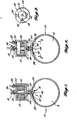
- FIGURE 1 is a schematic elevation view in partial cross section of a propellant augmented, gas dispensing device employing the flow control device of the invention shown in its position during propellant burn;
- FIGURE 2 is a view similar to FIGURE 1 showing the flow metering device during the gas dispensing mode; and
- FIGURE 3 is a view of the metering device taken along view line 3-=3 of FIGURE 2.
- Referring first to FIGURE 1, the propellant augmented, pressurized
gas dispensing device 10 is shown in schematic form and includes a pressurizedgas chamber 12, apropellant chamber 14; interconnectingconduit 16, and anexhaust conduit 18. Although these several portions of the dispensing device are shown as a single element, one of ordinary skill, however, will readily recognize that these portions will normally be made as separate components that are assembled and conventionally fastened together to form a unitary assembly. A lowpressure burst disc 20 is interposed in thepassage 22 defined withinconduit 16. A highpressure burst disc 24 is situated in theexhaust passage 26 defined within theexhaust conduit 18. A conventional squib orcap 28 is inserted in anappropriate recess 30 for ignition of apropellant 32 positioned within thepropellant chamber 14. The squib or cap can be of the electrically or percussion actuated type depending upon the environment of use of the gas dispensing device. One of ordinary skill will be able to integrate an appropriate ignition device as desired. - The gas dispensing device is generally constructed in accordance with techniques known in the art. The
passage 22 between thepropellant chamber 14 and thegas chamber 12 is equally sized with theexhaust passage 26 from thepropellant chamber 14. The sizing and construction of these passages is dictated by the desire to allow the heated and pressurized gas produced by the burning propellant easy ingress to thegas chamber 12 after the low pressure burst disc ruptures. Similarly, once the dispensing pressure has been reached and the highpressure burst disc 24 ruptures, theexhaust passage 26 is sized and constructed so that thepropellant chamber 14 is rapidly depressurized and any unused propellant is extinguished. - As stated above, however, in some applications it is desirable to meter or restrict the flow of gas from the dispensing device so as to control the rate of inflation, for example, of a raft or slide. Metered outflow cannot be accomplished by placing a restriction in the
exhaust passageway 26 because rapid depressurization of the propellant chamber cannot be achieved, and, thus, extinguishment of unused propellant cannot be achieved. On the other hand, a permanent restriction cannot be interposed in thepassageway 22 as the heated gas produced by the burning propellant will be unable to transfer its heat energy to the gas in the pressurizedgas chamber 12 at a sufficiently rapid rate, causing the pressure in the propellant chamber to rapidly rise and prematurely rupture the highpressure burst disc 24. As a result, the gas in thegas chamber 12 will not be raised to the desired temperature and pressure by the propellant - To solve this problem, the present invention provides a valve assembly, generally designated 34, that is associated with the
passageway 22 that extends between thepropellant chamber 14 and the pressurizedgas chamber 12. In the preferred embodiment illustrated in FIGURES 1 and 2, thevalve assembly 34 comprises aflexible flapper valve 36. The flapper valve comprises a disc-shaped member having asemicircular protrusion 38 along its periphery having a diameter of about one-third that of the disc-shaped member. Theprotrusion 38 serves as a connecting point to connect theflapper valve 36 to theinterior wall 40 of thegas chamber 12. The flapper valve is fastened to theinterior wall 40 by a suitableconventional fastener 42, for example, a small bolt or screw that extends through an opening in theprotrusion 38 into a threaded recess in the gas chamber wall. Theflapper valve 36 is positioned so that it overlies that inlet opening 44 into thepassage 22. In its relaxed state, theflapper valve 36 completely covers the inlet opening 44 and is biased toward that opening. The periphery of theflapper valve 36 contacts that portion of theinterior wall 40 of thegas chamber 12 surrounding the inlet opening 44 in sealing relationship. The central portion of the disc carries anorifice 46 that has a diameter less than the diameter of thepassage 22. Thevalve assembly 34 thus functions to allow flow in both directions through thepassage 22. In one direction, from the propellant chamber to the gas chamber, the gas flow causes theflapper valve 36 to flex away from the inlet opening 44, thus opening thepassage 22 and allowing full capacity flow therethrough. On the other hand, when the pressure is greater in thegas chamber 12 than in the propellant .chamber 14, the flapper valve flexes to the position covering the inlet opening 44 so that flow can occur only through themetering orifice 46. - Referring back to FIGURE 1, the propellant augmented, pressurized
gas dispensing device 10 of the present invention is operated by first initiating thesquib 28 to ignite thepropellant 32. As the propellant ignites, it produces hot, high pressure gas. As the pressure in thepropellant chamber 14 increases, the lowpressure burst disc 20 ruptures, allowing propellant gases to flow through thepassage 22. As the propellant gases enter thegas chamber 12, theflapper valve 36 flexes away from the inlet opening 44 to allow full flow through thepassage 22 intogas chamber 12. As the pressure in thepropellant chamber 14 andgas chamber 12 reaches the burst pressure of highpressure burst disc 24, that disc ruptures as illustrated in FIGURE 2. Because theexhaust passage 26 has a relatively large diameter, thepropellant chamber 14 can rapidly depressurize by exhausting through thepassage 26 past rupturedburst disc 24. As thepropellant chamber 14 depressurizes, a higher pressure still exists in thegas chamber 12, causing theflapper valve 36 to flex to its sealed position over the inlet opening 44 topassageway 22. Thus, high pressure gas in thegas chamber 12 can only exhaust through the smallerdiameter exhaust orifice 46. By choosing the size of theexhaust orifice 46, the flow rate of gas from thegas chamber 12 can be controlled at a desired level. In this manner, rapid depressurization of thepropellant chamber 14 can be achieved to assure extinguishment of theunused propellant 32. However, the pressurized gas in thegas chamber 12 can be more slowly metered out at a desired rate through theorifice 46 in theflapper valve 36. - The present invention has been described in relation to a preferred embodiment. One of ordinary skill after reading the foregoing specification will be able to effect various changes, substitution of equivalents and other alterations without departing from the broad concepts disclosed herein. It is therefore intended that the scope of Letters Patent granted hereon be limited only by the definition contained in the appended claims and equivalents thereof.
Claims (3)
1. A pressurized gas dispensing device including: , .
means defining a first chamber for holding a gas under pressure;
means defining a second chamber for holding a propellant; and
means defining a flow passage placing said first and second chambers in fluid communication, characterised by:
valve means associated with said flow passage for allowing bidirectional flow between said chambers at different flow rates, the flow rate from said second chamber to said first chamber being greater than the flow rate from said first chamber to said second chamber.
2. The gas dispensing device of Claim 1 wherein the end of said passage adjacent said first chamber has an inlet opening communicating with said first chamber, characterised in that the valve means comprises:
a seal member adapted to cover said inlet opening in sealing relationship, and means mounting said member for movement between a first position covering said opening and a second position spaced from said opening, said seal member having an opening therein aligned with said inlet opening when said seal member is in said first position, said opening in said seal member being smaller than said inlet opening.
3. The gas dispensing device of Claim 2 characterised in that the said seal member comprises:
a flexible member, a portion of said flexible member being affixed to the wall of said second chamber adjacent said inlet opening.
Applications Claiming Priority (2)
| Application Number | Priority Date | Filing Date | Title |
|---|---|---|---|
| US44156382A | 1982-11-15 | 1982-11-15 | |
| US441563 | 1982-11-15 |
Publications (2)
| Publication Number | Publication Date |
|---|---|
| EP0109790A2 true EP0109790A2 (en) | 1984-05-30 |
| EP0109790A3 EP0109790A3 (en) | 1985-12-18 |
Family
ID=23753382
Family Applications (1)
| Application Number | Title | Priority Date | Filing Date |
|---|---|---|---|
| EP83306684A Withdrawn EP0109790A3 (en) | 1982-11-15 | 1983-11-02 | Apparatus for controlling the outflow of gas from a propellant augmented, pressurized gas dispensing device |
Country Status (2)
| Country | Link |
|---|---|
| EP (1) | EP0109790A3 (en) |
| JP (1) | JPS59112832A (en) |
Cited By (2)
| Publication number | Priority date | Publication date | Assignee | Title |
|---|---|---|---|---|
| FR2669875A1 (en) * | 1990-11-30 | 1992-06-05 | Takata Corp | PNEUMATIC CUSHION DEVICE FOR THE PASSENGER SEAT BEFORE A VEHICLE. |
| US8753044B2 (en) | 2008-06-09 | 2014-06-17 | Uop Llc | L-valve construction for controlling solids flow in a liquid medium using standard pipe fittings |
Citations (2)
| Publication number | Priority date | Publication date | Assignee | Title |
|---|---|---|---|---|
| GB1351051A (en) * | 1970-06-16 | 1974-04-24 | Olin Corp | Apparatus for use in vehicle safety systems |
| US3833029A (en) * | 1972-04-21 | 1974-09-03 | Kidde & Co Walter | Method and apparatus for generating gaseous mixtures for inflatable devices |
-
1983
- 1983-11-02 EP EP83306684A patent/EP0109790A3/en not_active Withdrawn
- 1983-11-14 JP JP58212613A patent/JPS59112832A/en active Pending
Patent Citations (2)
| Publication number | Priority date | Publication date | Assignee | Title |
|---|---|---|---|---|
| GB1351051A (en) * | 1970-06-16 | 1974-04-24 | Olin Corp | Apparatus for use in vehicle safety systems |
| US3833029A (en) * | 1972-04-21 | 1974-09-03 | Kidde & Co Walter | Method and apparatus for generating gaseous mixtures for inflatable devices |
Cited By (3)
| Publication number | Priority date | Publication date | Assignee | Title |
|---|---|---|---|---|
| FR2669875A1 (en) * | 1990-11-30 | 1992-06-05 | Takata Corp | PNEUMATIC CUSHION DEVICE FOR THE PASSENGER SEAT BEFORE A VEHICLE. |
| US5217249A (en) * | 1990-11-30 | 1993-06-08 | Takata Corporation | Pressure relief for a passenger side air bag |
| US8753044B2 (en) | 2008-06-09 | 2014-06-17 | Uop Llc | L-valve construction for controlling solids flow in a liquid medium using standard pipe fittings |
Also Published As
| Publication number | Publication date |
|---|---|
| JPS59112832A (en) | 1984-06-29 |
| EP0109790A3 (en) | 1985-12-18 |
Similar Documents
| Publication | Publication Date | Title |
|---|---|---|
| US4600123A (en) | Propellant augmented pressurized gas dispensing device | |
| US3721456A (en) | Multiple stage inflater | |
| EP0792776A1 (en) | Hybrid inflator with projectile gas release | |
| CA1072147A (en) | All-pyrotechnic inflator | |
| US5078422A (en) | Gas inflator apparatus | |
| US5630619A (en) | Hybrid adaptive inflator for airbags | |
| US5195777A (en) | Air bag inflator | |
| US5803494A (en) | Air bag inflator | |
| US5582428A (en) | Hybrid adaptive inflator for airbags | |
| US4131300A (en) | Inflator for automobile safety device | |
| USRE30327E (en) | Inflator seal | |
| US3966228A (en) | Sequenced orifice fluid supply for occupant restraint system | |
| CA2131292A1 (en) | Hybrid Inflator with Staged Inflation Capability | |
| US3833029A (en) | Method and apparatus for generating gaseous mixtures for inflatable devices | |
| US20070138775A1 (en) | Inflator having a variable gas flow throttle | |
| US6382668B1 (en) | Air bag inflator | |
| US6189926B1 (en) | Airbag inflator with center discharge and soft onset | |
| US4054163A (en) | Tire inflator | |
| US3905515A (en) | Two-stage, pressure augmented inflator assembly | |
| US5890735A (en) | Hybrid inflator with diffuser end translating initiator boss | |
| US6029995A (en) | Vehicle occupant protection apparatus | |
| US6062598A (en) | Inflator with temperature responsive valve | |
| US5984351A (en) | Dual stage actuation system | |
| US6086094A (en) | Air bag inflator | |
| US5582425A (en) | Gas supply device for an air-bag |
Legal Events
| Date | Code | Title | Description |
|---|---|---|---|
| PUAI | Public reference made under article 153(3) epc to a published international application that has entered the european phase |
Free format text: ORIGINAL CODE: 0009012 |
|
| AK | Designated contracting states |
Designated state(s): DE FR GB SE |
|
| PUAL | Search report despatched |
Free format text: ORIGINAL CODE: 0009013 |
|
| AK | Designated contracting states |
Designated state(s): DE FR GB SE |
|
| STAA | Information on the status of an ep patent application or granted ep patent |
Free format text: STATUS: THE APPLICATION IS DEEMED TO BE WITHDRAWN |
|
| 18D | Application deemed to be withdrawn |
Effective date: 19860603 |
|
| RIN1 | Information on inventor provided before grant (corrected) |
Inventor name: JORGENSON, WALMER E. |