EP0109306A2 - Cache memory apparatus for computer - Google Patents
Cache memory apparatus for computer Download PDFInfo
- Publication number
- EP0109306A2 EP0109306A2 EP83306959A EP83306959A EP0109306A2 EP 0109306 A2 EP0109306 A2 EP 0109306A2 EP 83306959 A EP83306959 A EP 83306959A EP 83306959 A EP83306959 A EP 83306959A EP 0109306 A2 EP0109306 A2 EP 0109306A2
- Authority
- EP
- European Patent Office
- Prior art keywords
- disk
- record
- sector
- cache memory
- track
- Prior art date
- Legal status (The legal status is an assumption and is not a legal conclusion. Google has not performed a legal analysis and makes no representation as to the accuracy of the status listed.)
- Granted
Links
Images


Classifications
-
- G—PHYSICS
- G11—INFORMATION STORAGE
- G11B—INFORMATION STORAGE BASED ON RELATIVE MOVEMENT BETWEEN RECORD CARRIER AND TRANSDUCER
- G11B20/00—Signal processing not specific to the method of recording or reproducing; Circuits therefor
- G11B20/10—Digital recording or reproducing
- G11B20/18—Error detection or correction; Testing, e.g. of drop-outs
- G11B20/1883—Methods for assignment of alternate areas for defective areas
-
- G—PHYSICS
- G06—COMPUTING OR CALCULATING; COUNTING
- G06F—ELECTRIC DIGITAL DATA PROCESSING
- G06F12/00—Accessing, addressing or allocating within memory systems or architectures
- G06F12/02—Addressing or allocation; Relocation
- G06F12/08—Addressing or allocation; Relocation in hierarchically structured memory systems, e.g. virtual memory systems
- G06F12/0802—Addressing of a memory level in which the access to the desired data or data block requires associative addressing means, e.g. caches
- G06F12/0866—Addressing of a memory level in which the access to the desired data or data block requires associative addressing means, e.g. caches for peripheral storage systems, e.g. disk cache
-
- G—PHYSICS
- G11—INFORMATION STORAGE
- G11B—INFORMATION STORAGE BASED ON RELATIVE MOVEMENT BETWEEN RECORD CARRIER AND TRANSDUCER
- G11B2220/00—Record carriers by type
- G11B2220/20—Disc-shaped record carriers
Definitions
- the present invention is concerned with a cache memory system for use with a computer, to speed up transfers of data between the computer and a slow, disk memory.
- the invention is related to that described in our published European application EP-A-0080878 which forms part of the state of the art solely by virtue of Art 54(3)EPC.
- data is cached track by track but without waiting for the beginning of track index mark.
- the track position at the start of transfer is latched in a first register.
- a second register is zeroized at the beginning of the track and incremented as bytes are transferred. When the register contents match a complete track has been transferred.
- Data processing systems typically comprise a host computer and long-term memory storage devices including such devices as magnetic disk memory units and magnetic tape units. Communication from the host computer to the disk or tape memory system is generally made via a "channel" which comprises a defined set of signal connections over which must pass all information, including data as well as commands, control signals, status signals, request signals and so on. If a memory system is to be marketable, it must "interface” or mate directly with a channel identical with those with which prior memory systems have mated, thus being “plug compatible" with the host computer.
- any data subsystem shall not require modification to the host computer's programming instructions or "software" upon connection, i.e. that it be "software-transparent" to the host.
- the 4000/4305 solid-state disk system used a track remaining count which is similar to the emulated track position (ETP) of this invention. However, this track remaining count was not used for transferring orientation from a frame to a disk track; no magnetic disk memory was included in that system.
- ETP emulated track position
- the 8880/8650 disk system uses a reorient counter that counts an approximate full track revolution starting from the beginning of a record. If the 8880 director encounters errors reading a record, then the reorient counter in the device informs the director when the same record is about to pass under the read/write head again. This technique allows positive reorientation on a specific record on disk, but requires that orientation had been previously established on the disk.
- reliable orientation of the cache memory with respect to the disk drive is maintained by generating a table of "emulated track position" (ETP) values equal to the approximate addresses on disk of the. records being stored in the cache.
- the first ETP is the starting address which corresponds to the beginning address of the first record stored in the cache.
- the first ETP is thus a measure of the number of bytes from the index mark on the disk at which the starting point of the cached data was located. This value is saved as a "target" ETP, and is used to determine when a full track of data has been read.
- the next record's count field information is read and saved in a second register. The records on the track between the current orientation point and the index point can then be read.
- a current ETP value is initialized to zero in a third register.
- the data records are read from the index into the cache.
- the current ETP value is updated to count the number of bytes that have passed.
- the current ETP is compared to the target ETP. When it is greater than or equal thereto, the count field information from the last record read is compared against that stored in the storage director. If they are not equal, record reading continues. If they are, an indication is provided that the entire track has been read.
- the ETP values can be used to reliably retransfer orientation of data being read from the cache back to the disk drive in the event of an error occurring in the middle of a read operation, or in the event of other conditions previously discussed which require returning the channel program to disk.
- the ETP value for the record preceding the record upon which reorientation is to be obtained i.e. the first record called for by the channel, is selected from the table of ETP values.
- the selected ETP value is converted into an equivalent sector number and a residual value by dividing the emulated track position by the number of bytes per sector, which is fixed.
- the control module produces an interrupt signal which results in the director enabling the reading of records from disk after a further delay.
- the length of this further delay is controlled by the residual value, to align the beginning of reading with the correct record in the sector previously identified.
- the director enables the reading of address marks during a time period or "window" at the termination of the delay. In this manner, accurate detection of the desired record count field is obtained. Reliable and accurate reorientation is thus performed.
- the cache buffer memory system of the present invention is designed to operate in accordance with a prior art host computer in such a manner that no modification of the host's hardware or software is required.
- the cache buffer memory system of the invention should attach to the host computer through a conventional memory channel without modification; that is, it should be plug-compatible with, and software-transparent to, the host.
- the cache memory system is designed to operate in accordance with an IBM Corporation computer (or other computer plug-compatible with the IBM unit) of the class in which the channel is defined by IBM Publication GA22-6974-4 entitled, "I/O Interface Channel to Control Unit". This volume describes the channel specifications for plug-compatible memory systems.
- the cache buffered memory system is comprised in a disk drive memory system of the type previously sold by the present applicants, reconfigured to include asolid-state random access memory (RAM) which can be included within the enclosure containing the disk drive storage director unit.
- RAM asolid-state random access memory
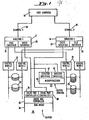
- FIG. 1 an overall view of a data processing system comprising a host computer system as defined above and a cache buffered memory system is shown.
- the host computer 10 is connected to a pair of storage directors 12 and 14 through channels 16 and 18, respectively.
- the directors and channels can be multiplied further, as well known in the art.
- Each director comprises a file interface 20 through which data is passed, via control modules indicated generally at 24, and thence to disk drive units indicated generally at 26.
- the disk drives 26 may be of various types.
- the control modules 24 to which the disk drives 26 are connected serve to interface varying types of disk drives with directors 12 and 14 such that different types of disk drives 26 together with appropriate control modules 24 can be used in conjunction with identical directors.
- the directors 12 and 14 are modified to additionally comprise cache interface units 28 which serve to interface the directors 12 and 14 with a cache buffer memory system according to the invention, which as schematically shown comprises a buffer unit 30 and a buffer control unit or manager 32.
- the buffer unit 30 has as its chief function the storage of data having been "staged" in anticipation of being required by the host computer. When the staged data is called for it can be very quickly read under control of a cache bus controller 35 out of a solid-state random access memory (RAM) array 34, the heart of the buffer unit, through one of a plurality of cache port controllers 36 and 38, respectively communicating with the directors 12 and 14, and thence to the host.
- RAM solid-state random access memory
- the typical prior art data path directly from the channel interface 16 through a director 12 and via a file interface 20 to a disk drive, sometimes termed "DASD” for "direct access storage device” 24 is shown.
- This data path is preserved and is used, as will be discussed below, for all ordinary read operations, when there is an error in the cache buffer, and during ordinary write operations.
- data is read from DASD 24, passes from the file interface 20 through the director 12 and thence to the cache buffer 30, under the control of the buffer manager unit 32.
- the data passes out of the buffer 30 through the director 12 and through the channel interface 16 to the host 10.
- parallel connection is provided between the two directors 12, the channels 16, the buffer 30 and the file interface 20.
- data may pass from a first director 12 from the buffer 30 enroute to the channel interface 16 after having been passed from DASD 24 to buffer 30 for staging by a second director 12.
- Such "paralleling" of directors 12 also permits data to move from the cache 30 to the host 10 even if the director 12 used to stage data into the cache buffer 30 then takes up another task before the data is actually called for by the host 10.
- the present IBM channel design provides a sequence of commands e.g. before an actual readout operation takes place.
- the host will issue a "START I/O" command to the channel.
- the channel in processing the "channel program” will issue a "SEEK” command to the director which will then cause the disk drive's head moving apparatus to access the proper track of the disk.
- a signal is passed back to the channel indicating that the head is in position.
- the disk drive examines the count and key data fields for that containing the record of interest; when it is juxtaposed to the read/write head, the record is read via the director to the host's main memory for processing.
- the channel program is also examined by the cache manager 32 for indications that the successive record is likely also to be called for by the host. If so, the buffer manager 32 then causes the director to have the succeeding record of records stored on the disk copied into the cache buffer 30 so that subsequent.read commands for successive records can more quickly be complied with, preferably making use of the invention of EP-A-0080876.
- data is staged from the disk into the buffer an entire track at a time.
- Such disk tracks typically comprise up to about 100 records, i.e. blocks of data separated from one another by gaps and identified by headers comprising index marks and the like.
- the 100 records may in turn be part of a disk file which may occupy many tracks, or in the case of large data files, up to several complete disk units.
- the cache buffered memory system be a field installable modification to a preexisting product thus adding minor additional cost and complexity to a memory system while permitting substantial performance advantages.
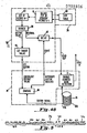
- Fig 3 shows one way in which the cache buffer can be added to a preexisting product while satisfying these conditions.
- Fig 3 shows four directors 12 and 14 each connected to a host computer via a channel 16.
- the directors 12 and 14 are each connected by way of the file interfaces 20 to the control modules (not shown) which,for example, convert the director commands to forms suitable for accessing a particular type of disk and so forth.
- the control modules are selected in accordance with the type of disk storage media to which they are to be connected, while the directors 12 and 14 are the same regardless of the type of disks used.
- Such directors and control modules may be as at present found in commercial products of the applicants, for example, in the Storage Technology Corporation Model 8880 disk controller and Model 8650 disk drive units respectively.
- a cache interface unit 28 which is connected to a buffer interface 36, connected to the bus controller 35 of the cache buffer unit 30.
- Control lines are also connected to the cache interface lines which run to the control interfaces 42 of the buffer manager 32.
- the cache buffer 30 is connected in parallel to each of the directors 12, 14 as is the buffer manager 32 which controls flow of data between the directors and the cache buffer.
- This is in distinction to, for example, a cache arrangement proposed by Memorex Corporation in which a single cache per director is interposed between the control module and the director.
- This arrangement has several disadvantages; one of the prime disadvantages is that more caches are required. While for a given performance level such single director caches can be made somewhat smaller, they are then less likely to be fully utilized.
- provision of a separate cache for each director does not allow two or more directors simultaneous access to the cache which is desirable. This alternate path access is very desirable in a highly active system to avoid path busy conditions.
- Such versatility is made possible by the arrangement of the invention as illustrated in Fig 3.
- the director 12 performs the functions of the director in the Model 8880; that is, it directs and interfaces to the control modules (which, for example, demultiplex the data-to serial form, for writing it to a disk) thus directly interfacing the drives themselves to the host channels by converting the data from the form in which it is stored on disk to one to which the channel can respond.
- the director 12 performs the additional functions of buffered data transfer, and execution of the stage operation, i.e. writing of data from the disk 26, (Fig 1) via the control module 24 into the cache buffer 30.
- the director 12 also provides buffer error recovery systems, which amount to bypassing of the buffer in favour of direct transfer of data from the disk 26 to channel interface 16, and the director communicates with the buffer manager 32.
- the director 12 performs switching functions, controlling the flow of data between the file interface 20, to which the disk units 26 are connected, the cache buffer 30 and the channel interface 16 to which is connected the host computer. These switching functions are controlled in accordance with instructions received from the buffer manager 32.
- the buffer manager 32, the cache buffer 30 and suitable control and data lines are added, so that the director 12 controls the data path in accordance with the instructions of the buffer manager 32.
- the buffer manager 32 determines whether a particular data record or series of records is likely to be called for-by the host and accordingly decides whether or not to "stage" it into the buffer 30 in advance of its actually being called for by the host in order to save access time.
- the decision involves examining the channel program data to look for track jump orders, end-of- file indicators, write indicators and the like, events unlikely to be encountered during reading of sequential data sets.
- the cache buffer 30, which performs the function of storing the data, is preferably organized by frames.
- the cache is subdivided into "domains" of a fixed size chosen such that the individual frames which correspond to logical tracks on disk fit as closely to integrally as possible within the domains.
- This cache space organization scheme is the subject of copending published application E P 0080877.
- the cache buffer 30 also stores the control information or header which defines each individual variable length logical frame by count, key and data fields as noted above.
- the buffer manager 32 in thepreferred embodiment comprises a miroprocessor 40 (Fig 1) and performs the manager function as follows.
- the chief function of the buffer manager 32 is to manage the space of the cache, that is, to direct the storage of data within the cache memory 30 and to retain the locations at which the specific tracks are stored in a "frame directory".
- the buffer manager 32 similarly schedules stage operations and communicates its instructions to the director 12.
- the buffer manager 32 also performs error management and recovery functions, which include switching the flow of data directly from the disk to the channel interface in the case of a catastrophic error.
- the remainder of the disk track is then desirably cached.
- accurate and fool-proof means must be provided to ensure that the proper correlation is maintained.
- the cache memory system is instead divided into domains which are sized to contain substantially integral numbers of frames of varying sizes to accommodate varying disk track sizes.
- the domains themselves can be reallocated to other types of frames when desired.
- FIG 4A will be referred to here to explain the way in which correspondence between the place on the disk at which a track of data to be stored in the cache is located and its address in the cache is maintained.
- a disk pack 26 is shown in Fig 4A.
- the disk pack may comprise a plurality of data storage disks 26B which are accessed by read/write heads 27 and a dedicated disk 26A which contains permanently encoded servo and sector identification information. This information is read by a dedicated head 27A.
- each data surface 26B is divided into a plurality of sectors 70. Circumferentially extending tracks 72 extend across the sector boundaries 70A.
- each track may be divided into one or more records indicated as Rl, R2, etc., which each in turn comprise a "header", i.e. count field, indicated at H and data indicated by D.
- the record boundaries do not necessarily coincide with the sector boundaries 70A.
- the count field information contains, for example, control information such as the length of the following data record, synchronization and address marks and is used to identify the specific record within the sector. Accordingly, in order to locate a particular record on disk, one must know the disk surface, the track number, the sector number, and the record number, the last of which is to be found within the count field.
- the first sector on the disk is located by an index mark 73 permanently written to the servo disk 26A from which sector numbers may be counted.
- the current sector address In order that correspondence can be maintained between the data read from the disk (which, as noted, does not begin with the index mark) the current sector address must be stored.
- the current sector number can be read from the dedicated disk surface 26A using the information coded thereon, as well understood in the prior art.
- the sector number is converted to an emulated track position (ETP) within the cache director 12, at 50, and this is stored as the target ETP in a target ETP register 51.
- ETP emulated track position
- a current ETP register 51 is initialized to zero and is used in building a table of ETP values at 60, each entry representing the relative ETP for a record.
- the record number within the first count field found is stored in a target record number register 52, also comprised within the cache director 12. Thereafter, reading of the records on the track between the starting position and the index mark proceeds, whereby the data is read into the cache array complete with the count fields.
- the current ETP value is incremented and an entry is made into the ETP table at 60, giving the beginning address for that record.
- a current ETP register 54 is set to a value equal to the number of bytes between the index mark and the home address field. The remainder of the records between the index mark and the point at which caching of the data began are then read from the disk to the cache array 34.
- the current ETP value in register 54 is incremented to reflect the number of bytes which have passed. Whenever the contents of current ETP register 54 are thus updated by the passage of another record, its value is compared at 53 with that stored in the target ETP register 51 to determine whether the first record staged is once again approaching the read/write head of the disk. When the current ETP is greater than or equal to the target ETP, data has been read from each sector of an entire track of data. When this occurs, the record number (abbreviated REC NO on the drawing) from the current record as comprised in a current record number register 55, to which the record numbers are copied as they pass by the head, is compared at 57 with the record number in the target record number register 52, written to previously as discussed above.
- REC NO the record number
- the target record number 52 equals the record number of the current record stored in current record number register 55, it may be concluded that all records in the sector in which staging was started have been read, and accordingly an indication may be provided as at 58 that a full track has been copied to the cache.
- the entries in the ETP table 60 for records staged prior to encountering the index mark are now adjusted from the relative values originally stored in the ETP table 60 to their actual values. This is required because the exact ETP value for the first record staged is only known after having read all records between the index and the first record.
- the ETP table 60 may then be copied from the director 12, where it is generated, to the cache array 34, where it is stored together with the data, as discussed further below.
- the header information written at the beginning of each frame in the cache must comprise means to indicate the relative locations of the records within the frame, so that, for example, when the host later calls for "record 3", there is a directory of cache addresses showing where this record is stored in the cache frame. For example, suppose that there are six records on a fiven track on a disk drive. The host calls for the first record. It is read directly from the disk to the host. Examination of the channel program by the buffer manager in accordance with EP-A-0080876 reveals that the subsequent records are likely to be called for as well.
- the cache director then consults its directory, locates the frame and examines the header, so as to be able to index a cache memory address pointer directly to the beginning of record 5, i.e. without reading through records 2 to 4, which is important if the cache is to operate efficiently.
- Fig 5 shows how the header which appears at the beginning of each frame can be organized to provide this wrap around capability.
- the records are not written into the cache frame assigned starting with a home address (HA) field. Instead, the stage operation begins with the first availble count field in order to minimize the time spent staging. Since the frame header is built as the records are being staged, the header entries will also start with the first available count field instead of the HA entry. To enable searching the header from the logical beginning to the logical end (as opposed to physical beginning to end), the following aids are introduced. Referring now to Fig 5, there is an HA (home address) pointer 70 saved in a known location in the frame header.
- HA home address
- This one byte pointer tells which entry in the header is the home address (HA) 70. This is used by the microcode to locate the logical beginning of the track in the cache. This HA pointer is written to the frame when the header is written.
- a wrap or end of frame entry is shown at 72. The wrap entry has a unique value in order to ensure that it is not mistaken for an ordinary record entry. This entry informs the microcode to wrap to the beginning of the header to find the remainder of the record entries, i.e. this entry locates the end of the last record in the frame.
- a null entry is indicated at 74. This is a four byte entry embedded in the header that has the hexadecimal value "00000000". This entry, like the wrap entry, is guaranteed to be unique.
- this entry simply is to signal that the end of the track has been reached.
- the header of Fig 5 wherein the records R4, R5 and R6 appear before the null entry 74 and home address 70, and records 1, 2 and 3 are placed between the home address 70 and the wrap entry 72, indicates that staging of this particular frame began with the fourth record on the track. Record 6 was the last record on the track, after which the null entry was written. Staging continued after staging of the home address pointer, and concluded with records 1, 2 and 3 after which the wrap entry, indicating the last record written to the physical cache frame was written.
- Each of the entries for the records Rl-R6 as shown comprises an ETP address, indicating the records starting location on the disk measured in bytes from the index mark and a word address "WA" indicating the starting location of the record within the cache memory. Correspondence is thus fully maintained between the locations of each individual record on the disk and in the cache memory.
- These entries, together with the null, home address, and wrap entries comprise a header data field 70B.
- Also comprised in the header stored at the beginning of each frame in the cache is a header control field 70A. This comprises three entries, DID, (device identification) , CYL (cylinder number of the staged track), HEAD (head number of the staged DASD track). These three entries clearly identify the location on the disk of the entire track stored in the frame.
- header control field 70A Also stored as part of the header control field 70A is the HAP, which is a pointer to the home address entry in the header data field 70B (the "known location" referred to above) so that if it is desired to locate the home address within the cache, it is not necessary to search through all the records stored previously thereto in the frame.
- HAP a pointer to the home address entry in the header data field 70B (the "known location" referred to above) so that if it is desired to locate the home address within the cache, it is not necessary to search through all the records stored previously thereto in the frame.
- a DL entry which indicates the length of the header data field.
- one of the objects of the invention is to provide a variable length header for a data field stored in a solid-state array. The DL entry is necessary to indicate the ending of the header data field 70A.
- this header format has a distinct advantage that only as many header entries need to be processed as actual records exist on disk in contradistinction to the method of e.g. providing a header entry for each sector.
- Fig 6 shows schematically the image of the track, including the header, in the cache.
- the image begins with the frame header 60 (comprising the header control field 70A and the header data field 70B, of Fig 5) which contains emulated track position values in bytes for beginning locations of the home address field and for record 0, for record 1, for record 2 and so on.
- the information staged from the DASD track follows the header.
- Fig 4B shows registers which may be used to establish the orientation and illustrates the interplay between the control module 24 and the director 12 in this operation
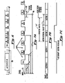
- Figs 7A, 7B and 7C comprise a detailed Illustration of the track format and of certain timing diagrams which further explain how the reorientation operation works.
- Fig 7A shows a more detailed view of one of the tracks.
- the track is deemed to begin with an index mark 73 (found on the servo disk 26A) followed by a home address mark, a gap, followed by a field indicating the length of record O, "RO Count", another gap, "RO Data”, another gap, "Rl Count”, another gap and so on.
- Fig 7B shows a correspondingly scaled diagram of the sectors into which the track is divided. As will be noted, the sectors do not correspond with the beginnings of the records, nor are there an integral number of records per sector.
- the typical disk pack with which the invention is designed to be used comprises a number of disk surfaces for the storage of data and a dedicated disk surface 26A which contains permanently encoded sector information-
- the dedicated disk surface 26A can be used to provide an indication of a sector 77 in the vicinity of a record to be read, but cannot be reli.ed upon to give an absolute indication of the place of beginning of a particular record.
- prior art operations when an error was found in trying to locate the. count field of a particular data record, it was essential to slip an entire revolution in an attempt to reorient on that same count field once again. If the same error occurred over and over again there was no way to obtain the data stored in the record, i.e. a permanent error was recorded.
- Recording of the emulated track positions according to the method of the invention provides a way out of this difficulty.
- the emulated track position of the record preceding the record of interest is used to locate its count field; thereafter the count field of the record sought is detected.
- the emulated track position of record 2 is first retrieved from the header data field 70B comprised in frame header field 60 (Fig 5).
- the location is shown on the diagram as ETP R2' and, as noted, occurs in sector 2.
- the sector is determined by dividing the ETP of R2 by the number of bytes per sector, and subtracting 1 from the result.
- the director looks for the beginning of sector 2 and is enabled at the beginning of sector 2, noted as "Director Waits” at 75 so that the count field of record 2 is thereafter detected, the director is enabled to transfer the data from the disk to the host computer beginning at the data field of Record 2. Accordingly, the "director waits" time begins at the start of sector 2.
- a timing window 69 is calculated using ETP R2 , that is, at the point measured in bytes after the index mark, where it is anticipated that Record 2 will begin. Reading is begun, i.e. the "READ" command is issued to the drive, at the end of the director waiting period. At this time, the drive searches for the next count field. When coinc-dence is detected, reading of the data can begin.
- the timing window is shown centered about the ETP position in Fig 7A. Since the beginning of the timing window must precede the desired count'field, the timing window is located by calculating the number of whole sectors in the emulated track position and adding additional bytes to locate the center of the count field detection window. In other words, the number of bytes per sector is divided into the emulated track position, so that the remainder, or residual value, is the number of bytes from the beginning of the next succeeding sector, sector 3 in Fig 7A, about which the timing window is to be centered.
- the total number of ETP bytes i.e. the number of bytes at which the record sought begins, measured from the index mark, is divided by the number of bytes per sector. For example, if the ETP is 325 bytes from the index mark and if a sector is 100 bytes long, then the ETP of the record sought for is 25 bytes past the beginning of the fourth sector (sector 3, counting from sector O). If the timing window desired is 40 bytes wide, then it should extend from 5 to 45 bytes after the start of sector 3.
- the dedicated disk 26A is used to locate the beginning of sector 3; when 5 more bytes have passed, the timing window is "opened".
- FIG. 4B Hardware to implement the operation of the detector during a reorientation operation as just described is depicted in Fig 4B.
- the director selects from ETP table 60 the ETP of the previous record, record Rl. (This is designated ETP of record N-1 in Fig 4B).
- the desired reorient count field is the one just prior to the field that requires processing by the channel, in tnis instance the Rl count field. Orienting on the prior count field enables processing by the .channel to immediately resume without slipping a full track operation.
- the value of ETP R1 is set into the register 63.
- the director 12 sets the target sector value to 2, which is the equivalent sector value.
- the control module 24 of the disk drive compares this equivalent sector value with the sector signal provided from the dedicated surface 26A, as indicated at 66.
- the control module produces an INTERRUPT SECTOR REACHED signal as shown in Fig 7C.
- the director 12 enables the reading of records from the disk after a further delay which is indicated at 67. This delay is calculated from the sector residual value.
- the director 12 begins reading of records stored on disk to the central processing unit.
- the timing window is established by enabling the address mark detection circuitry 71 in the drive for a duration of 20 track bytes. Since a count field can only occur every 186 track bytes, if a count field is encountered in this 20 track byte window, detection of the desired R2 count field is assured. A window is necessary for this read operation to ensure that the disk drive reliably detects the count field. When detection occurs, the SYNC IN signal is given.
- a program which processes data records may be reoriented from cache memory to the disk drive.
- control module 24 The functions of the control module 24 are the same as in systems without caching capability, so that the control module need not be modified to perform caching according to this invention.
- Figs 4B and 7. It will be appreciated that the reorientation of data flow from cache to disk is shown in Figs 4B and 7. It is essentially the inverse of the process of copying a track to cache as shown in Fig 4A. In both cases, a sector address is first looked for, and after the proper sector is located, then the header address is compared with a target header stored in a register so as to determine when the correct header has been reached. This is done in the case of reorientation to allow reading or writing data from the disk to commence at the correct point, and in the case of copying data from the disk to the cache (Fig 4A) to give the indication that a full track has been thus copied.
- the operation can be completed on the disk device to which the host's request was ostensibly addressed, thus fulfilling the foal of software transparency mentioned above.
- the problem with switching the operation to the disk drive is one of ensuring that the operation begins at the correct starting address on disk. Superficially, it would appear that it would be sufficient to compare the record identifier of the disk record supplied by the host against the identifier from the operation in the cache. However, there is no guarantee that all the record identifiers on the track are unique. A data integrity problem could thus be presented.
- This is overcome according to the present invention by using both the record identifier, which is an integral part of each record, and the ETP value associated with the starting point of the record on a track. Both variables are available at the time the cache is being used to satisfy the host's request.
Landscapes
- Engineering & Computer Science (AREA)
- Theoretical Computer Science (AREA)
- Physics & Mathematics (AREA)
- General Engineering & Computer Science (AREA)
- General Physics & Mathematics (AREA)
- Signal Processing (AREA)
- Memory System Of A Hierarchy Structure (AREA)
- Techniques For Improving Reliability Of Storages (AREA)
- Signal Processing For Digital Recording And Reproducing (AREA)
Abstract
Description
- The present invention is concerned with a cache memory system for use with a computer, to speed up transfers of data between the computer and a slow, disk memory. The invention is related to that described in our published European application EP-A-0080878 which forms part of the state of the art solely by virtue of Art 54(3)EPC. In this prior application data is cached track by track but without waiting for the beginning of track index mark. The track position at the start of transfer is latched in a first register. A second register is zeroized at the beginning of the track and incremented as bytes are transferred. When the register contents match a complete track has been transferred.
- The purpose of any caching technique is to reduce significantly the average time required for a record sought to be transferred to the main memory of the host computer. This is the purpose of the invention disclosed in our published application EP-A-0080875 which also forms part of the state of the art solely by virtue of Art 54(3)EPC. The present invention relates to further improvements in this area.
- Data processing systems typically comprise a host computer and long-term memory storage devices including such devices as magnetic disk memory units and magnetic tape units. Communication from the host computer to the disk or tape memory system is generally made via a "channel" which comprises a defined set of signal connections over which must pass all information, including data as well as commands, control signals, status signals, request signals and so on. If a memory system is to be marketable, it must "interface" or mate directly with a channel identical with those with which prior memory systems have mated, thus being "plug compatible" with the host computer.
- It is an object of the present invention to provide an improved memory system which is "plug-compatible" with a prior art host computer. ,
- Similarly, it is desirable if not commercially requisite that any data subsystem shall not require modification to the host computer's programming instructions or "software" upon connection, i.e. that it be "software-transparent" to the host.
- It is also an object of the present invention to provide a memory system which provides improved performance as noted above, while being software-transparent to the host.
- Occasionally, it is necessary to convert a channel program that was operating on a track image in cache memory (a frame) to operating on the actual track on the disk; that is, it becomes necessary to read a portion of a track from the disk, rather than the cache, or to write to a track which has been cached. In each case, it is necessary to recreate the specific record and field orientation that existed in cache before continuing the channel program with records from the disk track.
- The need for returning a channel program to disk arises in the following situations: 1) an error prevents data from being accessed in cache memory; 2) a write command is received in the channel program and it is deemed undesirable to write to cache memory; or 3) a sequential track required during multi-track processing is not located in cache memory.
- It is an object of the present invention to perform an accurate reorientation from the records stored in cache memory to the same records stored on the disk track. Further, it is an object of this invention to perform this reorientation operation within a single revolution of the disk, without necessarily waiting for the index mark on the disk track to provide reorientation.
- In the prior art, this was not always possible. Examples of related prior art systems include the Storage Technology Corporation 4000/4305 "solid-state disk" system, in which a solid-state memory effectively mimiced a magnetic disk system and the Storage Technology Corporation 8880/8650 disk system.
- The 4000/4305 solid-state disk system used a track remaining count which is similar to the emulated track position (ETP) of this invention. However, this track remaining count was not used for transferring orientation from a frame to a disk track; no magnetic disk memory was included in that system.
- The 8880/8650 disk system uses a reorient counter that counts an approximate full track revolution starting from the beginning of a record. If the 8880 director encounters errors reading a record, then the reorient counter in the device informs the director when the same record is about to pass under the read/write head again. This technique allows positive reorientation on a specific record on disk, but requires that orientation had been previously established on the disk.
- The system according to the present invention is defined in
claim 1 below. - In the preferred practice of the invention, reliable orientation of the cache memory with respect to the disk drive is maintained by generating a table of "emulated track position" (ETP) values equal to the approximate addresses on disk of the. records being stored in the cache. The first ETP is the starting address which corresponds to the beginning address of the first record stored in the cache. The first ETP is thus a measure of the number of bytes from the index mark on the disk at which the starting point of the cached data was located. This value is saved as a "target" ETP, and is used to determine when a full track of data has been read. The next record's count field information is read and saved in a second register. The records on the track between the current orientation point and the index point can then be read. When the disk's index mark is reached, a current ETP value is initialized to zero in a third register. The data records are read from the index into the cache. As each field is read, the current ETP value is updated to count the number of bytes that have passed. After each incrementation the current ETP is compared to the target ETP. When it is greater than or equal thereto, the count field information from the last record read is compared against that stored in the storage director. If they are not equal, record reading continues. If they are, an indication is provided that the entire track has been read.
- In accordance with the present invention, the ETP values can be used to reliably retransfer orientation of data being read from the cache back to the disk drive in the event of an error occurring in the middle of a read operation, or in the event of other conditions previously discussed which require returning the channel program to disk. In carrying out the invention, the ETP value for the record preceding the record upon which reorientation is to be obtained, i.e. the first record called for by the channel, is selected from the table of ETP values. The selected ETP value is converted into an equivalent sector number and a residual value by dividing the emulated track position by the number of bytes per sector, which is fixed. This produces an equivalent sector value which is supplied to the disk drive control module, where it is compared to the sector signal produced by the disk drive representing the sector currently rotating under the heads. When the desired sector is juxtaposed under the heads, the control module produces an interrupt signal which results in the director enabling the reading of records from disk after a further delay. The length of this further delay is controlled by the residual value, to align the beginning of reading with the correct record in the sector previously identified. The director enables the reading of address marks during a time period or "window" at the termination of the delay. In this manner, accurate detection of the desired record count field is obtained. Reliable and accurate reorientation is thus performed.
- The invention will be described in more detail, by way of example, with reference to the accompanying drawings, in which:
- Fig 1 is a block diagram of a system in which the invention may be used;
- Fig 2 shows the data and control paths in a simplified view of the system of Fig 1;
- Fig 3 shows in more detail connections between the directors, the file interface unit, and the cache buffer and manager units;
- Figs 4A and 4B depict the cache meanager operations during a stage to cache and during reorientations;
- Fig 5 shows a sample header fromat;
- Fig 6 depicts the header, home address, count and data fields of a disk track which has been stored in cache memory; and
- Figs 7A-7C are timing diagrams respectively showing the home address, count and data fields as read from a disk track, the track sector signal, and the sector value signal.
- As discussed above, the cache buffer memory system of the present invention is designed to operate in accordance with a prior art host computer in such a manner that no modification of the host's hardware or software is required. In particular, the cache buffer memory system of the invention should attach to the host computer through a conventional memory channel without modification; that is, it should be plug-compatible with, and software-transparent to, the host. In a preferred embodiment, the cache memory system is designed to operate in accordance with an IBM Corporation computer (or other computer plug-compatible with the IBM unit) of the class in which the channel is defined by IBM Publication GA22-6974-4 entitled, "I/O Interface Channel to Control Unit". This volume describes the channel specifications for plug-compatible memory systems. In a particularly preferred embodiment, the cache buffered memory system is comprised in a disk drive memory system of the type previously sold by the present applicants, reconfigured to include asolid-state random access memory (RAM) which can be included within the enclosure containing the disk drive storage director unit. Indeed, the addition of the cache feature may be made in such a manner as to be field-installable on previously shipped customer units at minimal additional complexity and cost, while substantial performance improvements may be realized.
- Referring now to Fig 1, an overall view of a data processing system comprising a host computer system as defined above and a cache buffered memory system is shown. The
host computer 10 is connected to a pair ofstorage directors channels file interface 20 through which data is passed, via control modules indicated generally at 24, and thence to disk drive units indicated generally at 26. As indicated schematically in the drawing, the disk drives 26 may be of various types. Thecontrol modules 24 to which the disk drives 26 are connected serve to interface varying types of disk drives withdirectors disk drives 26 together withappropriate control modules 24 can be used in conjunction with identical directors. As described thus far, the system of Fig 1 is conventional. In practising the present invention, thedirectors cache interface units 28 which serve to interface thedirectors buffer unit 30 and a buffer control unit ormanager 32. Thebuffer unit 30 has as its chief function the storage of data having been "staged" in anticipation of being required by the host computer. When the staged data is called for it can be very quickly read under control of acache bus controller 35 out of a solid-state random access memory (RAM)array 34, the heart of the buffer unit, through one of a plurality ofcache port controllers directors disk drive unit 26 as there is no latency time involved in the use of therandom access memory 34, as there is in the case of thedisk memories 26. - Referring now to Fig 2 a schematic view is shown of the data flow between the
file interface 20 and thehost interface 16 in the cache buffered memory system. The typical prior art data path directly from thechannel interface 16 through adirector 12 and via afile interface 20 to a disk drive, sometimes termed "DASD" for "direct access storage device" 24 is shown. This data path is preserved and is used, as will be discussed below, for all ordinary read operations, when there is an error in the cache buffer, and during ordinary write operations. In a staged read operation, however, data is read fromDASD 24, passes from thefile interface 20 through thedirector 12 and thence to thecache buffer 30, under the control of thebuffer manager unit 32. When thehost 10 then calls for the data actually to be supplied to it, the data passes out of thebuffer 30 through thedirector 12 and through thechannel interface 16 to thehost 10. It will be appreciated that parallel connection is provided between the twodirectors 12, thechannels 16, thebuffer 30 and thefile interface 20. This is to say, data may pass from afirst director 12 from thebuffer 30 enroute to thechannel interface 16 after having been passed fromDASD 24 to buffer 30 for staging by asecond director 12. Such "paralleling" ofdirectors 12 also permits data to move from thecache 30 to thehost 10 even if thedirector 12 used to stage data into thecache buffer 30 then takes up another task before the data is actually called for by thehost 10. - In this connection, it will be appreciated that the present IBM channel design provides a sequence of commands e.g. before an actual readout operation takes place. Typically, the host will issue a "START I/O" command to the channel. The channel in processing the "channel program" will issue a "SEEK" command to the director which will then cause the disk drive's head moving apparatus to access the proper track of the disk. When this has been done a signal is passed back to the channel indicating that the head is in position. After receipt of the "READ" command, the disk drive examines the count and key data fields for that containing the record of interest; when it is juxtaposed to the read/write head, the record is read via the director to the host's main memory for processing. In the present invention, the same practice is followed upon receiving of a first read command. However, the channel program is also examined by the
cache manager 32 for indications that the successive record is likely also to be called for by the host. If so, thebuffer manager 32 then causes the director to have the succeeding record of records stored on the disk copied into thecache buffer 30 so that subsequent.read commands for successive records can more quickly be complied with, preferably making use of the invention of EP-A-0080876. In a particularly preferred embodiment, data is staged from the disk into the buffer an entire track at a time. Such disk tracks typically comprise up to about 100 records, i.e. blocks of data separated from one another by gaps and identified by headers comprising index marks and the like. The 100 records may in turn be part of a disk file which may occupy many tracks, or in the case of large data files, up to several complete disk units. - As noted above, it is desirable that the cache buffered memory system be a field installable modification to a preexisting product thus adding minor additional cost and complexity to a memory system while permitting substantial performance advantages.
- Fig 3 shows one way in which the cache buffer can be added to a preexisting product while satisfying these conditions. Fig 3 shows four
directors channel 16. As in the prior art thedirectors directors director cache interface unit 28 which is connected to abuffer interface 36, connected to thebus controller 35 of thecache buffer unit 30. Control lines are also connected to the cache interface lines which run to the control interfaces 42 of thebuffer manager 32. Thus, to the preexisting Model 8880 unit one need only add cache interface cards to the directors, and install the cache buffer and Duffer manager units. Such an installation can be made to preexisting units in the field within a reasonable period of time and at reasonably modest additional cost. - It will be appreciated from inspection of Fig 3 that the
cache buffer 30 is connected in parallel to each of thedirectors buffer manager 32 which controls flow of data between the directors and the cache buffer. This is in distinction to, for example, a cache arrangement proposed by Memorex Corporation in which a single cache per director is interposed between the control module and the director. This arrangement has several disadvantages; one of the prime disadvantages is that more caches are required. While for a given performance level such single director caches can be made somewhat smaller, they are then less likely to be fully utilized. Moreover, provision of a separate cache for each director does not allow two or more directors simultaneous access to the cache which is desirable. This alternate path access is very desirable in a highly active system to avoid path busy conditions. Such versatility is made possible by the arrangement of the invention as illustrated in Fig 3. - As discussed above, in a preferred embodiment of the invention, it is configured as an add-on subsystem to a previously existing product, namely the Model 8880 disk controller manufactured by the applicants, Storage Technology Corporation. In this embodiment, the
director 12 performs the functions of the director in the Model 8880; that is, it directs and interfaces to the control modules (which, for example, demultiplex the data-to serial form, for writing it to a disk) thus directly interfacing the drives themselves to the host channels by converting the data from the form in which it is stored on disk to one to which the channel can respond. Thedirector 12 performs the additional functions of buffered data transfer, and execution of the stage operation, i.e. writing of data from thedisk 26, (Fig 1) via thecontrol module 24 into thecache buffer 30. Thedirector 12 also provides buffer error recovery systems, which amount to bypassing of the buffer in favour of direct transfer of data from thedisk 26 to channelinterface 16, and the director communicates with thebuffer manager 32. This is to say, thedirector 12 performs switching functions, controlling the flow of data between thefile interface 20, to which thedisk units 26 are connected, thecache buffer 30 and thechannel interface 16 to which is connected the host computer. These switching functions are controlled in accordance with instructions received from thebuffer manager 32. Thus, in the preferred embodiment in which the memory system of the invention is added on to a preexisting STC 8880 product, thebuffer manager 32, thecache buffer 30 and suitable control and data lines are added, so that thedirector 12 controls the data path in accordance with the instructions of thebuffer manager 32. - As noted above, the
buffer manager 32 determines whether a particular data record or series of records is likely to be called for-by the host and accordingly decides whether or not to "stage" it into thebuffer 30 in advance of its actually being called for by the host in order to save access time. (EP-A-0080876). Broadly, the decision involves examining the channel program data to look for track jump orders, end-of- file indicators, write indicators and the like, events unlikely to be encountered during reading of sequential data sets. - The
cache buffer 30, which performs the function of storing the data, is preferably organized by frames. In a preferred embodiment, the cache is subdivided into "domains" of a fixed size chosen such that the individual frames which correspond to logical tracks on disk fit as closely to integrally as possible within the domains. This cache space organization scheme is the subject of copending published application EP 0080877. Thecache buffer 30 also stores the control information or header which defines each individual variable length logical frame by count, key and data fields as noted above. - The
buffer manager 32 in thepreferred embodiment comprises a miroprocessor 40 (Fig 1) and performs the manager function as follows. The chief function of thebuffer manager 32 is to manage the space of the cache, that is, to direct the storage of data within thecache memory 30 and to retain the locations at which the specific tracks are stored in a "frame directory". Thebuffer manager 32 similarly schedules stage operations and communicates its instructions to thedirector 12. Thebuffer manager 32 also performs error management and recovery functions, which include switching the flow of data directly from the disk to the channel interface in the case of a catastrophic error. - After a first record has been determined to be part of a sequence of records, the remainder of the disk track is then desirably cached. This presents problems in address control and in correlation of the cached data with the data received or written on disk. In particular, inasmuch as the host's subsequent commands will be in terms of disk sector addresses and record numbers, not cache storage locations, accurate and fool-proof means must be provided to ensure that the proper correlation is maintained. Moreover, it is also necessary to provide means for determining when a full track has been staged into the cache so that the staging operation can be terminated at precisely the correct time.
- It would be a simple matter, of course, to begin staging at the index mark which is recorded at one location on each disk track and continue until the index mark was once again encountered. However, ordinarily the first record on the track will be that which is first accessed by the host, and hence most of the track will not have been read to the host at the time the determination to stage the remainder of the track is made. Therefore, the time taken for the disk to rotate the remainder of a revolution would be consumed while waiting for the index mark once again to be juxtaposed to the read/write head. This waste of time is clearly undesirable.
- Additional constraints are posed by the requirement that varying sizes of disk tracks be supported by the cache memory. This prevents the cache memory from being divided into subportions of "frames" of sizes equal to a particular disk track size and then simply assigning the starting addresses of each of the frames to the contents of the disk track as they are staged. In the preferred embodiment, the cache memory system is instead divided into domains which are sized to contain substantially integral numbers of frames of varying sizes to accommodate varying disk track sizes. The domains themselves can be reallocated to other types of frames when desired. (EP-A-0080877).
- Fig 4A will be referred to here to explain the way in which correspondence between the place on the disk at which a track of data to be stored in the cache is located and its address in the cache is maintained. A
disk pack 26 is shown in Fig 4A. The disk pack may comprise a plurality ofdata storage disks 26B which are accessed by read/write heads 27 and adedicated disk 26A which contains permanently encoded servo and sector identification information. This information is read by adedicated head 27A. As can be seen from Fig 4A and the enlarged portion thereof shown above, eachdata surface 26B is divided into a plurality ofsectors 70.Circumferentially extending tracks 72 extend across thesector boundaries 70A. As is usual, each track may be divided into one or more records indicated as Rl, R2, etc., which each in turn comprise a "header", i.e. count field, indicated at H and data indicated by D. As shown, the record boundaries do not necessarily coincide with thesector boundaries 70A. The count field information contains, for example, control information such as the length of the following data record, synchronization and address marks and is used to identify the specific record within the sector. Accordingly, in order to locate a particular record on disk, one must know the disk surface, the track number, the sector number, and the record number, the last of which is to be found within the count field. The first sector on the disk is located by anindex mark 73 permanently written to theservo disk 26A from which sector numbers may be counted. - If it is desired to cache a track of data from a disk to a cache memory, and if a portion of that track has already been read to the host computer, it would be preferable to begin caching with the remainder of the track, rather than wait for the
index mark 73 once again to be juxtaposed to the read/write head 27. Accordingly, when it is desired to stage a track to cache, a frame of the appropriate size is selected from the list of available frames of that size and beginning and ending addresses in thecache memory array 34 are then calculated by thecache manager 32 in accordance with the invention of our copending application No 83306851.3 filed 9.11.83 (publication number ). Data is then read from the disk to the cache beginning at a starting address. In order that correspondence can be maintained between the data read from the disk (which, as noted, does not begin with the index mark) the current sector address must be stored. The current sector number can be read from thededicated disk surface 26A using the information coded thereon, as well understood in the prior art. According to the present invention, the sector number is converted to an emulated track position (ETP) within thecache director 12, at 50, and this is stored as the target ETP in atarget ETP register 51. This initial ETP is a measure of the number of bytes from the index mark at which staging of data from the disk to thecache 34 was begun. Acurrent ETP register 51 is initialized to zero and is used in building a table of ETP values at 60, each entry representing the relative ETP for a record. The record number within the first count field found is stored in a targetrecord number register 52, also comprised within thecache director 12. Thereafter, reading of the records on the track between the starting position and the index mark proceeds, whereby the data is read into the cache array complete with the count fields. As each record is staged from DASD to cache, the current ETP value is incremented and an entry is made into the ETP table at 60, giving the beginning address for that record. When theindex mark 73 is reached, acurrent ETP register 54 is set to a value equal to the number of bytes between the index mark and the home address field. The remainder of the records between the index mark and the point at which caching of the data began are then read from the disk to thecache array 34. As each subsequent record is read, the current ETP value inregister 54 is incremented to reflect the number of bytes which have passed. Whenever the contents of current ETP register 54 are thus updated by the passage of another record, its value is compared at 53 with that stored in the target ETP register 51 to determine whether the first record staged is once again approaching the read/write head of the disk. When the current ETP is greater than or equal to the target ETP, data has been read from each sector of an entire track of data. When this occurs, the record number (abbreviated REC NO on the drawing) from the current record as comprised in a currentrecord number register 55, to which the record numbers are copied as they pass by the head, is compared at 57 with the record number in the targetrecord number register 52, written to previously as discussed above. When thetarget record number 52 equals the record number of the current record stored in currentrecord number register 55, it may be concluded that all records in the sector in which staging was started have been read, and accordingly an indication may be provided as at 58 that a full track has been copied to the cache. The entries in the ETP table 60 for records staged prior to encountering the index mark are now adjusted from the relative values originally stored in the ETP table 60 to their actual values. This is required because the exact ETP value for the first record staged is only known after having read all records between the index and the first record. The ETP table 60 may then be copied from thedirector 12, where it is generated, to thecache array 34, where it is stored together with the data, as discussed further below. - In order to use the "wraparound" method of writing data from disk into cache, whereby the operation can begin wherever convenient, rather than waiting for the index mark to be juxtaposed to the read/write head, the header information written at the beginning of each frame in the cache must comprise means to indicate the relative locations of the records within the frame, so that, for example, when the host later calls for "
record 3", there is a directory of cache addresses showing where this record is stored in the cache frame. For example, suppose that there are six records on a fiven track on a disk drive. The host calls for the first record. It is read directly from the disk to the host. Examination of the channel program by the buffer manager in accordance with EP-A-0080876 reveals that the subsequent records are likely to be called for as well. This determination consumes some rotational time, so thatrecords 3 to 6, beginning withrecord 3, are read into the cache beginning at a stated beginning address (BOT). When the index mark is reached, thecache director 12 initializes the present emulated track position (ETP) register 54 and proceeds to read the remainder of the track into the cache, ending withrecord 2. The host will thereafter presumably call forrecords records 2 to 4, which is important if the cache is to operate efficiently. - Fig 5 shows how the header which appears at the beginning of each frame can be organized to provide this wrap around capability. Stated slightly differently, because of the nature of the stage procedure, the records are not written into the cache frame assigned starting with a home address (HA) field. Instead, the stage operation begins with the first availble count field in order to minimize the time spent staging. Since the frame header is built as the records are being staged, the header entries will also start with the first available count field instead of the HA entry. To enable searching the header from the logical beginning to the logical end (as opposed to physical beginning to end), the following aids are introduced. Referring now to Fig 5, there is an HA (home address)
pointer 70 saved in a known location in the frame header. This one byte pointer tells which entry in the header is the home address (HA) 70. This is used by the microcode to locate the logical beginning of the track in the cache. This HA pointer is written to the frame when the header is written. A wrap or end of frame entry is shown at 72. The wrap entry has a unique value in order to ensure that it is not mistaken for an ordinary record entry. This entry informs the microcode to wrap to the beginning of the header to find the remainder of the record entries, i.e. this entry locates the end of the last record in the frame. A null entry is indicated at 74. This is a four byte entry embedded in the header that has the hexadecimal value "00000000". This entry, like the wrap entry, is guaranteed to be unique. The purpose of this entry simply is to signal that the end of the track has been reached. Thus, the header of Fig 5, wherein the records R4, R5 and R6 appear before thenull entry 74 andhome address 70, andrecords home address 70 and thewrap entry 72, indicates that staging of this particular frame began with the fourth record on the track. Record 6 was the last record on the track, after which the null entry was written. Staging continued after staging of the home address pointer, and concluded withrecords - Each of the entries for the records Rl-R6 as shown comprises an ETP address, indicating the records starting location on the disk measured in bytes from the index mark and a word address "WA" indicating the starting location of the record within the cache memory. Correspondence is thus fully maintained between the locations of each individual record on the disk and in the cache memory. These entries, together with the null, home address, and wrap entries comprise a header data field 70B. Also comprised in the header stored at the beginning of each frame in the cache is a
header control field 70A. This comprises three entries, DID, (device identification) , CYL (cylinder number of the staged track), HEAD (head number of the staged DASD track). These three entries clearly identify the location on the disk of the entire track stored in the frame. Also stored as part of theheader control field 70A is the HAP, which is a pointer to the home address entry in the header data field 70B (the "known location" referred to above) so that if it is desired to locate the home address within the cache, it is not necessary to search through all the records stored previously thereto in the frame. Finally, comprised in theheader control field 70A is a DL entry which indicates the length of the header data field. As noted above, one of the objects of the invention is to provide a variable length header for a data field stored in a solid-state array. The DL entry is necessary to indicate the ending of theheader data field 70A. - As discussed above, after the entire record has been read from the disk drive into the cache, it is necessary to adjust the ETP values for that portion of the record stored after initiation of the read operation and before detection of the index mark, because the RTP values are not precisely known until the latter time. This may be done in a preferred embodiment of the invention by building the header in the control store conventionally comprised in the
director 12. After the track has been entirely read into the cache, the header, complete and adjusted to reflect the exact ETP values for the records first stored, may be copied to the frame (in the cache memory 34) thus freeing the control store for future processing. This approach also provides the advantage that higher speed operations are possible than if the header entries were simultaneously being written to the cache. - It will be appreciated by those skilled in the art.that this header format has a distinct advantage that only as many header entries need to be processed as actual records exist on disk in contradistinction to the method of e.g. providing a header entry for each sector.
- Fig 6 shows schematically the image of the track, including the header, in the cache. The image begins with the frame header 60 (comprising the
header control field 70A and the header data field 70B, of Fig 5) which contains emulated track position values in bytes for beginning locations of the home address field and forrecord 0, forrecord 1, forrecord 2 and so on. The information staged from the DASD track follows the header. - When the host later desires to read a record stored in cache from disk, due to an error for example, the emulated track position values stored in header data field 70B are used in re-establishing orientation. Fig 4B shows registers which may be used to establish the orientation and illustrates the interplay between the
control module 24 and thedirector 12 in this operation, while Figs 7A, 7B and 7C comprise a detailed Illustration of the track format and of certain timing diagrams which further explain how the reorientation operation works. - The discussion above in connection with Fig 4A illustrated how the disk surface is divided into radially extending
sectors 77 and circumferentially extending tracks 72. Fig 7A shows a more detailed view of one of the tracks. The track is deemed to begin with an index mark 73 (found on theservo disk 26A) followed by a home address mark, a gap, followed by a field indicating the length of record O, "RO Count", another gap, "RO Data", another gap, "Rl Count", another gap and so on. Fig 7B shows a correspondingly scaled diagram of the sectors into which the track is divided. As will be noted, the sectors do not correspond with the beginnings of the records, nor are there an integral number of records per sector. - As discussed above in connection with Fig 4A, the typical disk pack with which the invention is designed to be used comprises a number of disk surfaces for the storage of data and a
dedicated disk surface 26A which contains permanently encoded sector information- Thededicated disk surface 26A can be used to provide an indication of asector 77 in the vicinity of a record to be read, but cannot be reli.ed upon to give an absolute indication of the place of beginning of a particular record. In prior art operations when an error was found in trying to locate the. count field of a particular data record, it was essential to slip an entire revolution in an attempt to reorient on that same count field once again. If the same error occurred over and over again there was no way to obtain the data stored in the record, i.e. a permanent error was recorded. Recording of the emulated track positions according to the method of the invention provides a way out of this difficulty. One can attempt to orient on the count field of the preceding record on the disk by using its ETP value stored in the header field, instead of looking for the count field of the record sought for. If an orientation can be established on the prior count field, then the succeeding count field will automatically be that of the record which is sought for. Accordingly, one source of permanent errors in disk drives is avoided by the generation of the ETP table according to the invention. It will be appreciated by those skilled in the art that if one desires to reorient operations from a cache to a disk, one must first locate the count field of the record which is, for example, being called for by a host, and that it is typically impossible to reorient on a particular count field in time to immediately supply the record to the host. Accordingly, if one simply output the emulated track position of the record which is to be located, one would have to wait an entire disk revolution before onecould begin sending the data from the disk to the channel. Having generated a full table of ETP values, according to the invention, one can instead reorient on the count field of the record preceding that of interest and can therefore begin reading data substantially immediately upon establishing orientation, thus speeding such reorient operations. Accordingly, when it is desired to reorient a read operation from the cache to the disk, the emulated track position of the record preceding the record of interest is used to locate its count field; thereafter the count field of the record sought is detected. This is explained in connection with Figs 7A to 7C. Assuming thatrecord 2 is to be located, the emulated track position ofrecord 2 is first retrieved from the header data field 70B comprised in frame header field 60 (Fig 5). The location is shown on the diagram as ETPR2' and, as noted, occurs insector 2. The sector is determined by dividing the ETP of R2 by the number of bytes per sector, and subtracting 1 from the result. Accordingly, the director looks for the beginning ofsector 2 and is enabled at the beginning ofsector 2, noted as "Director Waits" at 75 so that the count field ofrecord 2 is thereafter detected, the director is enabled to transfer the data from the disk to the host computer beginning at the data field ofRecord 2. Accordingly, the "director waits" time begins at the start ofsector 2. Atiming window 69 is calculated using ETPR2, that is, at the point measured in bytes after the index mark, where it is anticipated thatRecord 2 will begin. Reading is begun, i.e. the "READ" command is issued to the drive, at the end of the director waiting period. At this time, the drive searches for the next count field. When coinc-dence is detected, reading of the data can begin. - The timing window is shown centered about the ETP position in Fig 7A. Since the beginning of the timing window must precede the desired count'field, the timing window is located by calculating the number of whole sectors in the emulated track position and adding additional bytes to locate the center of the count field detection window. In other words, the number of bytes per sector is divided into the emulated track position, so that the remainder, or residual value, is the number of bytes from the beginning of the next succeeding sector,
sector 3 in Fig 7A, about which the timing window is to be centered. After this calculation is performed, a number of bytes equal to half the width of the timing window is subtracted from the value thus derived and it is at this point, determined by the byte count, that the timing window opens, enabling the director to look for the beginning of the R2 Count field. Accordingly, the total number of ETP bytes, i.e. the number of bytes at which the record sought begins, measured from the index mark, is divided by the number of bytes per sector. For example, if the ETP is 325 bytes from the index mark and if a sector is 100 bytes long, then the ETP of the record sought for is 25 bytes past the beginning of the fourth sector (sector 3, counting from sector O). If the timing window desired is 40 bytes wide, then it should extend from 5 to 45 bytes after the start ofsector 3. Thededicated disk 26A is used to locate the beginning ofsector 3; when 5 more bytes have passed, the timing window is "opened". - Hardware to implement the operation of the detector during a reorientation operation as just described is depicted in Fig 4B. Assume that it is desired to reorient on the R2 count field. As indicated at 61, the director selects from ETP table 60 the ETP of the previous record, record Rl. (This is designated ETP of record N-1 in Fig 4B). The desired reorient count field is the one just prior to the field that requires processing by the channel, in tnis instance the Rl count field. Orienting on the prior count field enables processing by the .channel to immediately resume without slipping a full track operation. The value of ETPR1 is set into the
register 63. It is converted into an equivalent sector value and a residual value by dividing it by the number of bytes per sector in the disk. This conversion is performed by thedivider 64. Assume as an example that the ETP is 474. That is, 474 bytes are in the gaps, the home address, the RO count, and the RO data fields prior to the Rl count field in Fig 7A. Dividing 474 by 156 (the number of bytes in a sector) gives a quotient of 3 and a remainder (resudual value) of 6. Thequotient 3 identifies the target sector value assector 2. (Since the numbering of sectors begins with O, the third sector is sector 2). - As indicated at 65, the
director 12 sets the target sector value to 2, which is the equivalent sector value. Thecontrol module 24 of the disk drive compares this equivalent sector value with the sector signal provided from thededicated surface 26A, as indicated at 66. As in response to a conventional SET SECTOR command, when the heads 27 of the diskpack reach sector 2, the control module produces an INTERRUPT SECTOR REACHED signal as shown in Fig 7C. In response to the INTERRUPT SECTOR REACHED signal, thedirector 12 enables the reading of records from the disk after a further delay which is indicated at 67. This delay is calculated from the sector residual value. At the termination of this delay, indicated at thepoint 68 in Fig 7A, thedirector 12 begins reading of records stored on disk to the central processing unit. This is accomplished by detecting the first count field which occurs within a timing window indicated at 69 in Fig 7A. The timing window is established by enabling the addressmark detection circuitry 71 in the drive for a duration of 20 track bytes. Since a count field can only occur every 186 track bytes, if a count field is encountered in this 20 track byte window, detection of the desired R2 count field is assured. A window is necessary for this read operation to ensure that the disk drive reliably detects the count field. When detection occurs, the SYNC IN signal is given. - In this manner, a program which processes data records may be reoriented from cache memory to the disk drive. This has been accomplished by the use of the table of ETP values. It should be noted that one advantage of the table of ETP values is that it allows reorientation even though all of the bytes in the gaps have not been stored in the cache memory. By using the ETP values according to the present invention, reorientation is possible even though there is not a strict correspondence between records on a disk track and the data copied to the
cache memory 30. - The functions of the
control module 24 are the same as in systems without caching capability, so that the control module need not be modified to perform caching according to this invention. - It will be appreciated that the reorientation of data flow from cache to disk is shown in Figs 4B and 7. It is essentially the inverse of the process of copying a track to cache as shown in Fig 4A. In both cases, a sector address is first looked for, and after the proper sector is located, then the header address is compared with a target header stored in a register so as to determine when the correct header has been reached. This is done in the case of reorientation to allow reading or writing data from the disk to commence at the correct point, and in the case of copying data from the disk to the cache (Fig 4A) to give the indication that a full track has been thus copied. The reorientation process described in connection with Figs 4B and 7 is slightly complicated by the fact that the sector preceding that containing the record at which reading from the disk is desired to begin must be looked for because the record's starting location or disk cannot be assumed to be coincident with the beginning of the sector within which they are located.
- In the event of an error indication generated by the cache managing, it is important that "orientation" or data path establishment be redirected from the cache to the disk device so that the cache can be "cut out" of the data path, thus returning the path to that which would have existed if the cache had never been added to the long-term memory storage system. This must be done as discussed above in such a way that the addition of the cache requires no modifications to the host, i.e. that it be plug compatible and software transparent thereto. Accordingly, when the system of the invention detects an error in the cache system it is inappropriate to terminate the host's request with the indication that the operation cannot be completed. In fact, the operation can be completed on the disk device to which the host's request was ostensibly addressed, thus fulfilling the foal of software transparency mentioned above. The problem with switching the operation to the disk drive is one of ensuring that the operation begins at the correct starting address on disk. Superficially, it would appear that it would be sufficient to compare the record identifier of the disk record supplied by the host against the identifier from the operation in the cache. However, there is no guarantee that all the record identifiers on the track are unique. A data integrity problem could thus be presented. This is overcome according to the present invention by using both the record identifier, which is an integral part of each record, and the ETP value associated with the starting point of the record on a track. Both variables are available at the time the cache is being used to satisfy the host's request.
- It will be appreciated that there has been described a method of control of a cache buffer memory which satisfies the needs of the art and objects of the invention listed above. By generating emulated track position information as to each record as data is read from disk into cache, one has available at all times an accurate correlation between disk and present cache address if for some reason it is desired to switch channel orientation back to the disk from the cache. Furthermore, correct maintenance of the ETP register allows one to know accurately when the entire disk track has been read. This in turn permits one to write data from disk to cache without waiting for the index mark to be juxtaposed to the read/write head. Finally, provision of a frame header generated when the data is written to the cache permits the header to be of a length proportional to the number of records in the cache, while providing a direct correspondence between the location of records in the cache and their locations on disk,
Claims (10)
Applications Claiming Priority (2)
| Application Number | Priority Date | Filing Date | Title |
|---|---|---|---|
| US44181882A | 1982-11-15 | 1982-11-15 | |
| US441818 | 1982-11-15 |
Publications (3)
| Publication Number | Publication Date |
|---|---|
| EP0109306A2 true EP0109306A2 (en) | 1984-05-23 |
| EP0109306A3 EP0109306A3 (en) | 1986-07-02 |
| EP0109306B1 EP0109306B1 (en) | 1989-02-01 |
Family
ID=23754414
Family Applications (1)
| Application Number | Title | Priority Date | Filing Date |
|---|---|---|---|
| EP19830306959 Expired EP0109306B1 (en) | 1982-11-15 | 1983-11-15 | Cache memory apparatus for computer |
Country Status (5)
| Country | Link |
|---|---|
| EP (1) | EP0109306B1 (en) |
| CA (1) | CA1212780A (en) |
| DE (2) | DE3390324T1 (en) |
| GB (1) | GB2140595B (en) |
| WO (1) | WO1984002017A1 (en) |
Families Citing this family (3)
| Publication number | Priority date | Publication date | Assignee | Title |
|---|---|---|---|---|
| JPS6093172U (en) * | 1983-11-30 | 1985-06-25 | パイオニア株式会社 | Recorded information reproducing device |
| JPH01130243A (en) * | 1987-11-17 | 1989-05-23 | Hitachi Ltd | Fault recovering system for storage device |
| US12386748B2 (en) | 2022-03-31 | 2025-08-12 | Intel Corporation | Selective fill for logical control over hardware multilevel memory |
Family Cites Families (6)
| Publication number | Priority date | Publication date | Assignee | Title |
|---|---|---|---|---|
| US3566358A (en) * | 1968-03-19 | 1971-02-23 | Bevier Hasbrouck | Integrated multi-computer system |
| US4007448A (en) * | 1974-08-15 | 1977-02-08 | Digital Equipment Corporation | Drive for connection to multiple controllers in a digital data secondary storage facility |
| US4075686A (en) * | 1976-12-30 | 1978-02-21 | Honeywell Information Systems Inc. | Input/output cache system including bypass capability |
| US4241420A (en) * | 1978-11-01 | 1980-12-23 | Bank Computer Network Corporation | Disk data control |
| US4394733A (en) * | 1980-11-14 | 1983-07-19 | Sperry Corporation | Cache/disk subsystem |
| EP0080878A3 (en) * | 1981-11-27 | 1985-06-26 | Storage Technology Corporation | Cache memory and method of control for use with magnetic disks |
-
1983
- 1983-11-14 GB GB08417054A patent/GB2140595B/en not_active Expired
- 1983-11-14 DE DE19833390324 patent/DE3390324T1/en not_active Withdrawn
- 1983-11-14 WO PCT/US1983/001770 patent/WO1984002017A1/en not_active Ceased
- 1983-11-15 CA CA000441190A patent/CA1212780A/en not_active Expired
- 1983-11-15 EP EP19830306959 patent/EP0109306B1/en not_active Expired
- 1983-11-15 DE DE8383306959T patent/DE3379124D1/en not_active Expired
Also Published As
| Publication number | Publication date |
|---|---|
| WO1984002017A1 (en) | 1984-05-24 |
| GB2140595A (en) | 1984-11-28 |
| DE3390324T1 (en) | 1985-02-21 |
| EP0109306A3 (en) | 1986-07-02 |
| GB2140595B (en) | 1986-11-12 |
| CA1212780A (en) | 1986-10-14 |
| GB8417054D0 (en) | 1984-08-08 |
| EP0109306B1 (en) | 1989-02-01 |
| DE3379124D1 (en) | 1989-03-09 |
Similar Documents
| Publication | Publication Date | Title |
|---|---|---|
| US4780808A (en) | Control of cache buffer for memory subsystem | |
| JP2635023B2 (en) | Label writing method for file data | |
| US5530829A (en) | Track and record mode caching scheme for a storage system employing a scatter index table with pointer and a track directory | |
| US5818654A (en) | Apparatus and process for managing defective headerless sectors | |
| US4001883A (en) | High density data storage on magnetic disk | |
| US6295176B1 (en) | Apparatus and process for identifying sectors in a headerless sector data track | |
| US5384669A (en) | Combining small records into a single record block for recording on a record media | |
| EP0559142B1 (en) | Data storage format conversion method and system, data access method and access control apparatus | |
| US6219729B1 (en) | Apparatus and method for providing for efficient communication between high and low-level processing engine of a disk drive formatter | |
| US5414570A (en) | Tape marks recorded in user data blocks having identifications of the recorded tape marks | |
| US4507693A (en) | Control apparatus for rotation type storage device | |
| US5539914A (en) | Method and system for preprocessing data block headers during access of data in a data storage system | |
| US4797755A (en) | System and method for transferring data between a plurality of disks and a memory | |
| JPH04288615A (en) | Cash-equipped dasd subsystem for controlling rotating position of disk and its executing method | |
| US4494157A (en) | Information readout apparatus | |
| CA2046720C (en) | Nonsynchronous channel/dasd communication system | |
| JPH07225715A (en) | Method and system for accessing data in cache | |
| US4651277A (en) | Control system for a magnetic disk drive unit | |
| US4918651A (en) | Method and disk controller architecture for zero latency data read | |
| EP0109306B1 (en) | Cache memory apparatus for computer | |
| US4480277A (en) | Information processing system | |
| EP0080878A2 (en) | Cache memory and method of control for use with magnetic disks | |
| US6745300B1 (en) | Magnetic disk device and disk access method therefor | |
| EP0456690B1 (en) | Read/write head buffer | |
| CA2008522A1 (en) | Read/write head buffer |
Legal Events
| Date | Code | Title | Description |
|---|---|---|---|
| PUAI | Public reference made under article 153(3) epc to a published international application that has entered the european phase |
Free format text: ORIGINAL CODE: 0009012 |
|
| AK | Designated contracting states |
Designated state(s): DE FR GB IT |
|
| PUAL | Search report despatched |
Free format text: ORIGINAL CODE: 0009013 |
|
| AK | Designated contracting states |
Kind code of ref document: A3 Designated state(s): DE FR GB IT |
|
| 17P | Request for examination filed |
Effective date: 19860829 |
|
| 17Q | First examination report despatched |
Effective date: 19870602 |
|
| GRAA | (expected) grant |
Free format text: ORIGINAL CODE: 0009210 |
|
| AK | Designated contracting states |
Kind code of ref document: B1 Designated state(s): DE FR GB IT |
|
| ITF | It: translation for a ep patent filed | ||
| GBDW | Gb: gb designation withdrawn | ||
| RBV | Designated contracting states (corrected) |
Designated state(s): DE FR IT |
|
| REF | Corresponds to: |
Ref document number: 3379124 Country of ref document: DE Date of ref document: 19890309 |
|
| ET | Fr: translation filed | ||
| ITTA | It: last paid annual fee | ||
| PGFP | Annual fee paid to national office [announced via postgrant information from national office to epo] |
Ref country code: FR Payment date: 19891130 Year of fee payment: 7 |
|
| PLBE | No opposition filed within time limit |
Free format text: ORIGINAL CODE: 0009261 |
|
| STAA | Information on the status of an ep patent application or granted ep patent |
Free format text: STATUS: NO OPPOSITION FILED WITHIN TIME LIMIT |
|
| PG25 | Lapsed in a contracting state [announced via postgrant information from national office to epo] |
Ref country code: DE Effective date: 19891218 |
|
| 26N | No opposition filed | ||
| PG25 | Lapsed in a contracting state [announced via postgrant information from national office to epo] |
Ref country code: FR Effective date: 19910731 |
|
| REG | Reference to a national code |
Ref country code: FR Ref legal event code: ST |