EP0108807B1 - Wafer transfer apparatus - Google Patents
Wafer transfer apparatus Download PDFInfo
- Publication number
- EP0108807B1 EP0108807B1 EP83902069A EP83902069A EP0108807B1 EP 0108807 B1 EP0108807 B1 EP 0108807B1 EP 83902069 A EP83902069 A EP 83902069A EP 83902069 A EP83902069 A EP 83902069A EP 0108807 B1 EP0108807 B1 EP 0108807B1
- Authority
- EP
- European Patent Office
- Prior art keywords
- wafer
- support member
- slots
- along
- trolley
- Prior art date
- Legal status (The legal status is an assumption and is not a legal conclusion. Google has not performed a legal analysis and makes no representation as to the accuracy of the status listed.)
- Expired - Lifetime
Links
Images



Classifications
-
- B—PERFORMING OPERATIONS; TRANSPORTING
- B65—CONVEYING; PACKING; STORING; HANDLING THIN OR FILAMENTARY MATERIAL
- B65G—TRANSPORT OR STORAGE DEVICES, e.g. CONVEYORS FOR LOADING OR TIPPING, SHOP CONVEYOR SYSTEMS OR PNEUMATIC TUBE CONVEYORS
- B65G47/00—Article or material-handling devices associated with conveyors; Methods employing such devices
- B65G47/74—Feeding, transfer, or discharging devices of particular kinds or types
- B65G47/90—Devices for picking-up and depositing articles or materials
- B65G47/91—Devices for picking-up and depositing articles or materials incorporating pneumatic, e.g. suction, grippers
- B65G47/912—Devices for picking-up and depositing articles or materials incorporating pneumatic, e.g. suction, grippers provided with drive systems with rectilinear movements only
-
- H—ELECTRICITY
- H10—SEMICONDUCTOR DEVICES; ELECTRIC SOLID-STATE DEVICES NOT OTHERWISE PROVIDED FOR
- H10P—GENERIC PROCESSES OR APPARATUS FOR THE MANUFACTURE OR TREATMENT OF DEVICES COVERED BY CLASS H10
- H10P72/00—Handling or holding of wafers, substrates or devices during manufacture or treatment thereof
- H10P72/30—Handling or holding of wafers, substrates or devices during manufacture or treatment thereof for conveying, e.g. between different workstations
- H10P72/34—Handling or holding of wafers, substrates or devices during manufacture or treatment thereof for conveying, e.g. between different workstations the wafers being stored in a carrier, involving loading and unloading
- H10P72/3411—Handling or holding of wafers, substrates or devices during manufacture or treatment thereof for conveying, e.g. between different workstations the wafers being stored in a carrier, involving loading and unloading involving loading and unloading of wafers
-
- H—ELECTRICITY
- H10—SEMICONDUCTOR DEVICES; ELECTRIC SOLID-STATE DEVICES NOT OTHERWISE PROVIDED FOR
- H10P—GENERIC PROCESSES OR APPARATUS FOR THE MANUFACTURE OR TREATMENT OF DEVICES COVERED BY CLASS H10
- H10P72/00—Handling or holding of wafers, substrates or devices during manufacture or treatment thereof
- H10P72/30—Handling or holding of wafers, substrates or devices during manufacture or treatment thereof for conveying, e.g. between different workstations
- H10P72/34—Handling or holding of wafers, substrates or devices during manufacture or treatment thereof for conveying, e.g. between different workstations the wafers being stored in a carrier, involving loading and unloading
- H10P72/3411—Handling or holding of wafers, substrates or devices during manufacture or treatment thereof for conveying, e.g. between different workstations the wafers being stored in a carrier, involving loading and unloading involving loading and unloading of wafers
- H10P72/3412—Batch transfer of wafers
-
- H—ELECTRICITY
- H10—SEMICONDUCTOR DEVICES; ELECTRIC SOLID-STATE DEVICES NOT OTHERWISE PROVIDED FOR
- H10P—GENERIC PROCESSES OR APPARATUS FOR THE MANUFACTURE OR TREATMENT OF DEVICES COVERED BY CLASS H10
- H10P72/00—Handling or holding of wafers, substrates or devices during manufacture or treatment thereof
- H10P72/50—Handling or holding of wafers, substrates or devices during manufacture or treatment thereof for positioning, orientation or alignment
- H10P72/53—Handling or holding of wafers, substrates or devices during manufacture or treatment thereof for positioning, orientation or alignment using optical controlling means
-
- H—ELECTRICITY
- H10—SEMICONDUCTOR DEVICES; ELECTRIC SOLID-STATE DEVICES NOT OTHERWISE PROVIDED FOR
- H10P—GENERIC PROCESSES OR APPARATUS FOR THE MANUFACTURE OR TREATMENT OF DEVICES COVERED BY CLASS H10
- H10P72/00—Handling or holding of wafers, substrates or devices during manufacture or treatment thereof
- H10P72/70—Handling or holding of wafers, substrates or devices during manufacture or treatment thereof for supporting or gripping
- H10P72/78—Handling or holding of wafers, substrates or devices during manufacture or treatment thereof for supporting or gripping using vacuum or suction, e.g. Bernoulli chucks
-
- H—ELECTRICITY
- H10—SEMICONDUCTOR DEVICES; ELECTRIC SOLID-STATE DEVICES NOT OTHERWISE PROVIDED FOR
- H10P—GENERIC PROCESSES OR APPARATUS FOR THE MANUFACTURE OR TREATMENT OF DEVICES COVERED BY CLASS H10
- H10P72/00—Handling or holding of wafers, substrates or devices during manufacture or treatment thereof
- H10P72/06—Apparatus for monitoring, sorting, marking, testing or measuring
- H10P72/0606—Position monitoring, e.g. misposition detection or presence detection
-
- Y—GENERAL TAGGING OF NEW TECHNOLOGICAL DEVELOPMENTS; GENERAL TAGGING OF CROSS-SECTIONAL TECHNOLOGIES SPANNING OVER SEVERAL SECTIONS OF THE IPC; TECHNICAL SUBJECTS COVERED BY FORMER USPC CROSS-REFERENCE ART COLLECTIONS [XRACs] AND DIGESTS
- Y10—TECHNICAL SUBJECTS COVERED BY FORMER USPC
- Y10S—TECHNICAL SUBJECTS COVERED BY FORMER USPC CROSS-REFERENCE ART COLLECTIONS [XRACs] AND DIGESTS
- Y10S294/00—Handling: hand and hoist-line implements
- Y10S294/907—Sensor controlled device
-
- Y—GENERAL TAGGING OF NEW TECHNOLOGICAL DEVELOPMENTS; GENERAL TAGGING OF CROSS-SECTIONAL TECHNOLOGIES SPANNING OVER SEVERAL SECTIONS OF THE IPC; TECHNICAL SUBJECTS COVERED BY FORMER USPC CROSS-REFERENCE ART COLLECTIONS [XRACs] AND DIGESTS
- Y10—TECHNICAL SUBJECTS COVERED BY FORMER USPC
- Y10S—TECHNICAL SUBJECTS COVERED BY FORMER USPC CROSS-REFERENCE ART COLLECTIONS [XRACs] AND DIGESTS
- Y10S414/00—Material or article handling
- Y10S414/135—Associated with semiconductor wafer handling
- Y10S414/137—Associated with semiconductor wafer handling including means for charging or discharging wafer cassette
- Y10S414/138—Wafers positioned vertically within cassette
-
- Y—GENERAL TAGGING OF NEW TECHNOLOGICAL DEVELOPMENTS; GENERAL TAGGING OF CROSS-SECTIONAL TECHNOLOGIES SPANNING OVER SEVERAL SECTIONS OF THE IPC; TECHNICAL SUBJECTS COVERED BY FORMER USPC CROSS-REFERENCE ART COLLECTIONS [XRACs] AND DIGESTS
- Y10—TECHNICAL SUBJECTS COVERED BY FORMER USPC
- Y10S—TECHNICAL SUBJECTS COVERED BY FORMER USPC CROSS-REFERENCE ART COLLECTIONS [XRACs] AND DIGESTS
- Y10S414/00—Material or article handling
- Y10S414/135—Associated with semiconductor wafer handling
- Y10S414/141—Associated with semiconductor wafer handling includes means for gripping wafer
Definitions
- This invention relates to apparatus for the precise placement of a first element at a location on a second element, e.g. placing semiconductor wafers in holders or boats.
- the present invention seeks to address these problems.
- apparatus for placing a first element (11) at a precise location on a second element (14), said apparatus comprising: a support member (42) for supporting said first element (11) while said member is translated toward said second element (14) along a placement direction (Y); first transport means (20, 110, 54, 50, 56, 201) for moving said support member or said second element along a direction (Z) transverse to said placement direction; and characterised in that the apparatus further comprises: sensing means (400, 401, 402, 403, 405) located on said support member for sensing whether or not a variation in the shape (132) of said second element (14) at a predetermined location thereon is located at a point along said transverse direction (Z) at which it is aligned with said support member (42); the sensing means comprising: an energy-beam source (400) adapted and positioned to direct an energy beam along a path that intersects said variation in shape (132) when said support member (42) and said variation in shape (132) are
- the invention provides apparatus for inserting a semiconductor wafer in a holding boat of the type having at least two slots in which said wafer is received, comprising a wafer support member or paddle for supporting said wafer, rotation means for rotating said support member about a rotation axis by the angle necessary to cause edges of said wafer to be received at the centres of said slots, and placement means for translating said rotated support member along a single placement direction, parallel to said rotation axis so as to place said wafer in said slots in said holding boat.
- wafers are placed in said slots without their edges scraping the walls of the slots.
- the invention provides in further preferred embodiments apparatus for translating a member along a prescribed path such that the member may be repeatably moved away from and brought back to a precise location, said apparatus comprising a track with a top and a bottom surface, said surfaces following said path, a trolley adapted to be supported on said track, rollers supporting said trolley on said top and bottom surfaces of said track and flexure means mounted between the trolley and the rollers at the bottom surface of the track, said flexure means being adapted to tightly press said rollers against said top and bottom surfaces of said track so as to support said trolley on said track without slope or lost motion therebetween.
- the invention provides apparatus for transferring at least one semiconductor wafer between a first holding boat and a second holding boat, comprising a wafer support member for supporting said wafer during transfer, an arm to which said support member is attached, arm movement means for moving said arm between said first and second boats, first boat support means for supporting said first boat, second boat support means for supporting said second boat, at least one of said boat support means comprising a track on which there is supported by roller bearings a trolley to which said boat is attached.
- the invention provides apparatus for retaining on a semiconductor-wafer transfer apparatus a wafer holder of the type placed in furnaces and of the type having two upper, slotted rails, said apparatus comprising a first retention member with two grooves for receiving one said rail at two locations spaced along the rail, a second retention member with one groove for receiving the other said rail at a first location along said rail, and a third retention member with a flat, non-grooved surface for engaging said other rail at a second location along said other rail.
- said rails are constrained at only three locations and allowed to assume a natural position at the fourth location so as to accommodate misalignment of the rails.
- a general feature of the apparatus described below is the provision on a support member (or "paddle") of a sensor for sensing the alignment of the support member with some known location, recognizable by a known variation in shape (e.g., a slot), on to which an element (e.g., a semiconductor wafer) is placed by the support member.
- a support member or "paddle” of a sensor for sensing the alignment of the support member with some known location, recognizable by a known variation in shape (e.g., a slot), on to which an element (e.g., a semiconductor wafer) is placed by the support member.
- sensing is done in advance of placement; sensing is accomplished by transmitting an energy beam (e.g., light) along a path intersecting with slots in a holder for semiconductor wafers and the output of the sensor is processed to determine the locations of the holder at which the wafer paddle is so aligned that wafers supported thereon would be received at a centers of the slots; these alignment locations are stored and used later on to align the holder when wafers are actually transferred; two sensors, one for slots in each of two rails in the holder, are provided on the wafer paddle; and mirrors on a central portion of the paddle reflect light travelling between sources and sensors located on outer portions of the paddle, only the central portion actually being received inside the boat.
- an energy beam e.g., light
- Another general feature of the described apparatus is picking up semiconductor wafers with vacuum openings positioned nearer the periphery than the centre of the wafer so as to provide greater certainty as to the locations of the wafer edges with respect to the pickup element despite warpage of the wafers.
- the vacuum openings are surrounded by raised ridges so that the central region of the wafer paddle, inside of the openings, is lower than the openings so as to provide room for wafer warpage without the warped portions of the wafer touching the rest of the paddle; individual pressure sensors are provided for the vacuum openings so that initial contact of the paddle with a wafer can be sensed by the presence of a vacuum in just one opening; and apparatus for moving the wafer paddle relative to the wafer is adapted to slow down after sensing closure of one opening.
- the wafer paddle is suitably made by laminating Teflon (polytetrafluoroethylene) to aluminium.
- Teflon polytetrafluoroethylene
- the aluminium is grooved and supplied with tubes for supplying vacuum to openings in the ptfe surface.
- the wafer may be placed or picked up softly by using a damper to control the speed of final placement and initial pickup.
- sensors establish slots locations and the rotation angle is determined from the sensor outputs; a rotatable arm driven by a stepping motor and cam accomplish the rotation.
- the apparatus described below also features a trolley supported by sets of rollers on the top and bottom surfaces of a track, a flexure element pressing the rollers against the track surfaces.
- track/trolley apparatus is used to support and translate wafer holders with respect to a wafer paddle; a double set of such tracks and trolleys provides precise translation of the wafer paddle in a plane; a chain and sprocket driven by stepping motors and coupled with an encoder drive and measure the location of a trolley.
- the described apparatus retains a quartz boat for semiconductor wafers by gripping its two upper rails at three points by means of grooves into which the rails are received and by providing a non-grooved flat surface at a fourth point, to thereby accomodate boats with misaligned rails.
- the above described features of the described apparatus have numerous advantages: Providing sensors on the wafer paddle itself eliminates the need for knowing the absolute locations of either the paddle or the wafer holder, and thus less precise manufacturing tolerances are required and variations with time and change of environment are automatically accommodated. Wafers are placed into holder slots without scraping the slot walls so as to avoid creating particulate contamination. The wafer holders and paddle arm are translated precisely to prescribed locations without generating contaminants from the transport mechanism. Soft placement and pickup of wafers further cuts down on contaminants by preventing break off of parricles from the edges of the wafers. Warped wafers are accommodated by the features of the vacuum pickup, and warped boats are accommodated by the boat retention features.
- Fig. 1 is a perspective, somewhat diagrammatic view of said preferred embodiment.
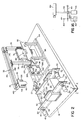
- Fig. 2 is a partially cutaway view of said embodiment with the cover removed.
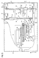
- Fig. 3 is a plan view, partially cutaway, of said embodiment.
- Fig. 4 is a sectional view taken along 4-4 of Fig. 3.
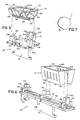
- Fig. 5 is a perspective view of a quartz boat and retention apparatus therefor.
- Fig. 6 is a perspective view of a plastic boat, retention apparatus therefor, and a wafer alignment mechanism.
- Fig. 7 shows a typical wafer.
- Fig. 8 is a perspective view of a wafer handling paddle.
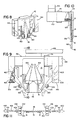
- Fig. 9 is a sectional view of a wafer handling paddle showing suction openings and the optical location system.
- Fig. 10 is a sectional view taken along 10-10 of Fig. 9.
- Fig. 11 is a plan view, partially cutaway, of a quartz boat and a wafer handling paddle, and including, in diagrammatic form, the lenses, fiber optic bundles, source, and sensor of the optical slot sensing system.
- Figs. 12a and 12b are plan views of the wafer handling paddle and arm, showing the arm in two different angular positions (Fig. 12b is a partial view of one end of the arm).
- Fig. 13 is a somewhat diagrammatic plan view of the plastic and quartz boat trolley drive mechanisms.
- Fig. 14 is a sectional view taken along 14-14 of Fig. 13.
- Fig. 15 is a cross-sectional view of a plastic boat showing the wafer handling paddle and wafer alignment mechanism.
- Fig. 16 is a diagrammatic view of the mechanism for effecting soft placement and pickup of wafers.
- wafer handling device 10 for transferring semiconductor wafers 11 to and from plastic boats 12 to quartz boats 14 (in which the wafers are held when put into a diffusion furnace).
- Device 10 has base 16 (upon which cover 18 rests), trolleys 20, 22 for transporting the boats, and wafer transfer arm 32.
- Trolleys 20, 22 extend through slots 24, 26 respectively, of cover 18. A lip runs along both sides of the slots.
- Trolley 20 has affixed to its upper end platform 28, which supports quartz boat 14.
- Trolley 22 has affixed to its upper end platform 30 to support plastic boats 12.
- Both trolleys 20, 22 include channel shaped member 116 which is bolted between the upper and lower portions of the trolley (shown in Fig. 14 for trolley 22).
- Drip shield 118 which is attached to cover 18, fits inside the channel shaped opening created by member 116.
- Wafer transfer arm 32 is attached to vertical arms 34, 36 which extend through slot 38 in cover 18.
- a right angle member 40 connects arm 32 to aluminum wafer paddle 42, which has four suction openings 154 in the center leg 46 of the paddle, for gripping wafers.
- suction openings 154 At each vacuum opening 154, there is a picture-frame-like raised ridge (.010 elevation (0.254 mm)) surrounding the opening. The openings and ridges are located so as to grip wafers nearer their edges than their centers.
- paddle 42 has Teflon sheet 13 laminated to one face of center leg 46.
- the Teflon sheet (which has been etched to aid bonding) is bonded to the aluminum with chemgrip epoxy adhesive (Chemplest Inc., Wayne, N.J.) and then machined to the desired thickness (about 0.020 inches 0.508 mm).
- the overall thicness of center leg 46 is about 0.12 inches 3.048 mm; this dimension is kept small to permit the paddle to be moved very close to either end of the boats so that wafers can be loaded into slots at the ends.
- Vacuum tubes 164 are inserted in grooves in the aluminum prior to application of the Teflon sheet. Vacuum fittings and lines (not shown) connect tubes 164 to a vacuum source.
- Four solenoid valves and four sensors (not shown), one each in each vacuum line, individually control and sense the vacuum at each opening 154.
- An evacuated tank is connected to the main vacuum line and, with a main solenoid valve, is used to maintain vacuum at minimum of two openings 154 in the event of loss of the main source of vacuum.
- the pressure sensors in the vacuum lines provide information on which two openings have the best vacuum, and thus the best grip on a wafer.
- the valves for the other two openings are then shut to enable the evacuated tank to maintain vacuum only at the other two openings.
- the tank can maintain the vacuum long enough to allow the system to set down the wafer being held in one of the boats.
- Servo motor 48 is attached to sprocket 49 by helical coupling 51.
- Chain 55 (typical of other chains described herein, is a cable chain belt made by Winfred M. Berg, Inc., which has no backlash and very little stretch) runs between sprocket 49 (which is supported by bearings in the same manner as the other sprockets) and sprocket 53.
- a fixed lower plate and an adjustable upper plate (not shown) support sprockets 49 and 53 and allow movement of the sprockets with regard to each other in order to provide for tension adjustment of chain 55.
- Sprocket 53 is coupled to sprocket 50 by clutch assembly 57 and helical coupling 52.
- Trolley 20 rests on aluminum track 110 (Fig. 2) and is affixed to chain 54, which runs between sprockets 50, 56.
- the support structure for sprockets 50, 56 is movable along the "Z" axis (Fig. 2) to allow for tension adjustment of chain 54.
- Trolley 20 is affixed to chain 54 by flexible fastening assembly 201 which is bolted to the trolley and to the chain.
- Incremental optical encoder 60 is connected to sprocket 56 by helical coupling 61. Redundant incremental optical encoder 47 may be provided (connected to sprocket 50 by helical coupling 45).
- Encoder 60 provides 0.0003 inch 0.00762 mm resolution along the Z direction for motion of trolley 20.
- Servo motor 62 is attached to sprocket 63 by helical coupling 65.
- Chain 67 runs between sprocket 63 and sprocket 69.
- Tension in chain 67 is adjustable in the same manner as described for chain 55.
- Sprocket 69 is coupled to sprocket 64 by clutch assembly 71 and helical coupling 66.
- Trolley 22 rests on aluminum track 112 (Figs. 2 and 14) and is affixed to chain 68 which runs between sprockets 64 and 70.
- the support structure for sprockets 64, 70 is movable along the "Z" axis to allow for tension adjustment of chain 68.
- Trolley 20 is affixed to chain 68 in the same manner as trolley 22 is affixed to chain 54.
- Incremental optical encoder 74 is connected to sprocket 70 by a helical coupling. Clutches 57 and 71 prevent the trolleys from breaking a wafer (by pressing it too hard against the paddle) during a malfunction. Even though clutch slippage shifts the relationship between the servo motors and the trolleys, it does not affect the relationship between encoders 60, 74 and the trolleys, and thus no information on trolley position is lost when clutch slippage occurs, because the encoders are coupled directly to the sprockets driving the trolleys.
- FIG. 2 and 3 there is shown the mechanism supporting wafer transfer arm 32.
- Vertical arms 34, 36 are affixed to trolley 76 which is attached to vertical aluminum track 78.
- vertical track 78 is affixed to trolley 80 which is attached to horizontal aluminum track 82 that is rigidly attached to base 16 by support members 84.
- Stepper motor 86 is coupled to sprocket 88 by clutch assembly 90.
- Chain 92 runs between sprockets 88 and 94.
- Sprocket 94 is connected to sprocket 96 by shaft 98 extending through vertical member 300.
- Chain 100 wrapped around sprockets 96, 102, 104, 106, is attached to vertical arm 34, by coupling 107, which enables movement of chain 100 to translate vertical arm 34.
- Coupling 107 includes pin 109, affixed to chain 100, which fits into a corresponding hole in block 111, which is affixed to arm 34.
- stepper motor 86 driving chain 100 which is connected to vertical arm 34 by coupling 107.
- Pin 109 is inserted into a corresponding hole in the block so that it can freely rotate when the motion of arm 34 changes from the "X" direction to "Y” direction or from the "Y” direction to the "X” direction.
- Carriage 76 rides on track 78 allowing vertical motion, while carriage 80 rides on track 82 allowing horizontal motion.
- aluminum tracks 110 and 112 are attached to support structure 114, which is rigidly affixed to base 16.
- teflon retaining members 120, 122, 124, 126, for retaining quartz boat 14, are affixed to platform 28.
- Member 126, located at one end of platform 28, is fixed while member 124, located at the other end of the platform is flexibly attached to the platform.
- Members 124, 126 engage opposite ends of one lower boat rail 130.
- Member 120, located along the back side of platform 28, has an aluminum back 121 to keep it rigid, while members 122, 123, on the opposite side, are flexibly attached to the platform by spring-steel flexures at their bases.
- Fixed member 120 has a groove 202, parallel to and able to engage an upper boat rail 128, and vertical cut-out 204 to accommodate center band 134 of the quartz boat.
- Flexible member 123 has a groove 210 parallel to and capable of engaging an upper boat rail on one side of the center band.
- Flexible member 122 has no groove for engaging an upper rail but instead a flat tapered surface; the absence of a groove helps accommodate angular misalignment between the two upper rails, by permitting the upper rail adjacent member 122 to assume any location along its ungrooved surface. This assures that the upper rails are snugly held in the grooves of the other retention member.
- Quartz boat 14 which mates with the retaining members, consists of two upper rails 128, and one or two lower rails 130.
- the upper rails contain slots 132, for receiving wafers.
- the rails are attached together by three semi-circular bands 134 and two end pieces 136, such that the rails are parallel with respect to each other. Wafers rest in the slots and on top of the bottom rails.
- Misalignment between the two slotted, upper rails is common, resulting either from errors during the boat's manufacture or from warping of the boat in the diffusion furnaces.
- the misalignment can be angular or simply a relative shift along the Z direction, but the usual result is that a wafer must be rotated about the Y axis in order for it to be inserted into a pair of slots without scraping the slot walls.
- FIG. 6 there are shown the retention members for plastic boats 12.
- Aluminum channel sections 139 located at either end of platform 30, support flexible retaining members 138, 142 which are teflon and attached by a spring-steel plate 143 to the channel sections 139.
- Aluminum channel section 141 located at the center of platform 30, supports fixed teflon retaining member 140, which is located between the two boats 12.
- Retaining members 138, 140, 142 slide into grooves 145 located at both ends of the boats.
- the flexibility of members 138, 142 securely holds the boats in place, while the rigidity of member 140 maintains precise positioning of the boats with respect to the platform.
- the plastic boats 12 have open bottoms and side slots 144 for receiving wafers.
- Alignment rollers 146, 148 extend longitudinally along the top of platform 30 and can contact wafers through the open bottoms of the boats. As shown in Fig. 15, roller 146 is coupled to motor 150 by chain 152.
- wafer paddle 42 has center leg 46 and two outer, optical legs 156.
- Light from pulsed infrared LED source 400 (about 10,000 pulses per second, each pulse only about 10 microseconds duration, manufactured by Texas Instruments under designation TIL31) passes through lens 401, fiberoptic bundle 402 (which extends through the hollow of arm member 168 to the paddle), and lens 403 at the paddle.
- Light reflected by mirror 160 and received at lens 405 travels back through another fiberoptic bundle (not shown), through another lens (not shown), to an infrared sensor (manufactured by Texas Instruments under designation TI81; not shown).
- Identical arrangements of source, lenses, fiberoptic bundles, and sensor are used for both sides of the paddle.
- the lenses at the source and sensor ends of the fiberoptic bundles are chosen to focus light from the sources into the bundles and from the bundles onto the sensors.
- the lenses on the paddles are chosen to assure that the light beam is focused at approximately the slot location so as to minimize the beam width at that location and thereby increase the system's ability to discriminate the center of a slot.
- Mirror 60 is trapezoidal in cross section.
- the narrow base of the trapezoid does the light reflecting and is only about 0.030 inches (0.762 mm) wide so as to reflect only a light beam of the same width.
- the adjoining tapered surfaces of the mirror (corresponding to the slanting legs of the trapezoidal cross section) reflect away other light.
- the light beam is focused at the location of slot interception, so as to be narrowest at that location, and thereby improve the ability to discriminate the slot center.
- the beam width is on the order of the slot width at such location, and no wider than 150% of the slot width.
- the ends of the fiberoptic bundles are moved with the arm and only come into alignment with the sources and sensors when the paddle is lowered into its measurement position in the quartz boat; at other paddle positions, when no light measurements need to be made anyway, the bundles are displaced from the sources and sensors.
- Wafer transfer arm 32 consists of solid member 166 and hollow member 168.
- Motor 170 is connected to cam 172, which has pin 174 (Fig. 12) extending into slot 176 in member 166.
- Member 166 is rigidly attached to member 140 which supports paddle 42.
- Members 140 and 168 are attached by spring-steel flexure 141, which permits y-axis rotation between member 166 and paddle 42.
- Fig. 16 Shown in Fig. 16 is the mechanism for effecting soft placement and soft pickup of wafers from the quartz boat, so as to avoid contamination from pieces of the wafer breaking away from the wafer's edge when a wafer is placed down (or picked up) hard.
- Vacuum-operated actuator 410 and spring 412 are affixed to one end of pivoting arm 414.
- Frictionless damper 416 is affixed to the far end of member 168 of the wafer transfer arm.
- Rod 418 connecting damper 416 and member 168 slides freely through pivoting arm 414 until enlarged portion 420 contacts the pivoting arm.
- Soft placement is achieved by first activating actuator 410 to pull arm 414 downward, thus lifting the wafer transfer paddle slightly, and then, when the paddle is in position for soft placement, releasing actuator 410, which under the force of spring 412 quickly moves arm 414 upward, to allow paddle downward motion to be resisted solely by the force of damper 416.
- Soft pickup is achieved simply by activating the vacuum actuator. Damper 416 resists downward movement of the actuator, and thus a slow pickup of the paddle is provided. Vertical movement of the paddle during soft placement and pickup is on the order of 100 to 200 mils 2.54 to 5.08 mm, and the time interval for such movement is on the order of 1/2 second. Adjustable counterweight 184 on the far end of arm member 168 is adjusted to give the paddle (loaded with a wafer) a downward impact force of about 50 grams. A manual-adjustable, variable-flow valve in the vacuum line is used to adjust the speed of descent and ascent.
- aluminum track 112 which is typical of tracks 78, 82, 110, has inclined surfaces 188 running longitudinally along its top and bottom.
- Each roller 190 rotates on a stationary shaft which is pressed into a roller bar and held by a set screw. A spacer on the shaft prevents contact between roller 190 and roller bar 189, while a snap ring holds the roller on the shaft.
- the rollers are pressed against surfaces 188 of the tracks by action of parallel spring steel flexures 185, 187, which connect the carrier to one of the roller bars.
- Parallel string steel flexures 185, 187 provided on trolleys 20, 22, 76, 80 work as a parallelogram to soak up variations without slop or backlash and to keep the trolleys from tilting, thereby supporting the trolleys on the tracks without any lost motion therebetween.
- Bottom surfaces 188 need not be machined as precisely as bottom surfaces 188, as the flexures will soak up variations in the bottom surfaces.
- Adjustment mechanisms (not shown) are provided on boat trolleys 20, 22 to permit vertical adjustment and tilt adjustment (about X and Z axes) between the boat retention members and the trolley.
- Stepper motor 150 coupled to roller 146 below the plastic boats 12, is activated for a short interval, to rotate roller 146, which, in turn, rotates wafers 11, until the flat sides 192 of the wafers are all facing downward (i.e., parallel to platform 30).
- Roller 148 moves freely and assists in guiding the wafers into the desired position.
- Roller 146 ceases to cause wafer rotation once a wafer's flat side is facing downward.
- the time interval during which stepper motor 150 is activated is made sufficiently long to assure that all wafers reach the desired position.
- An empty quartz boat 14 is placed onto platform 28, and retained there by members 120, 122, 124, 126.
- the paddle is lowered into the boat, and trolley 20 is moved to move the paddle past the slots.
- the height of the paddle is adjusted until the light path is at such a height that there consistently occurs variation in the light sensor output at slot locations. This adjustment need not be repeated for each transfer, as the quartz boat retention members assure that the quartz rails and the slots therein are always at the same height.
- wafer paddle 42 is moved into one end of the interior of the empty quartz boat. Center leg 46 of the paddle passes between upper rails 128, while optical legs 156 pass along the outside of the boat. Quartz-boat trolley 20 is then advanced so as to move (at a speed of about 1 in/sec (25.4 mm/sec)) the paddle past a group of five slots 132 near the end of the boat closest to retention member 123 (the one with groove 210). Measurements are made at that end because only there is it assured that both boat rails are at a known vertical position (at the other end, one of the rails could be too high or too low due to rail misalignment for the slot sensors to work properly.
- the locations of slots 132 are determined by sensing the variation in light intensity at the light sensors. Light travelling from the sources is reflected by mirrors 160 back to the sensors. That light path is blocked except when a slot 132 is encountered, as shown in Fig. 9. Maximum light transmission occurs at the precise center of each slot. Locations of alignment between the paddle and the ten slots (five on each rail) are determined from the outputs of encoder 60 and the light sensors. The ten locations are then processed to determine what wafer rotation angle theta (Fig. 11) is required to cause wafers carried by the paddle to be aligned with the slots. One wafer rotation angle is generally good for all pairs of slots (because variations in slot spacing between the two upper rails is very much less than the variation in longitudinal position of the rails). But different wafer rotations for each slot pair can also be provided if necessary.
- paddle 42 is rotated about the Y axis by precisely that angle. This is accomplished by activating stepper motor 170, which rotates cam 172 causing pin 174 (Figs. 12a and 12b) to translate longitudinally in slot 176 in member 166 of arm 32. This causes member 166, which is rigidly affixed to paddle 42, but flexibly attached to member 168 via spring-steel flexure 141, to rotate about the Y axis in relation to member 168.
- paddle 42 is moved in a second pass through quartz boat 14. Again the output of encoder 60 is stored, and alignment locations are determined from points of maximum light. If the new set of locations show adequate alignment, wafer transfer is begun. If alignment is inadequate, a new wafer rotation angle theta is determined, and stepper motor 170 is activated to position paddle 42 at the new angle, and another pass is made through the quartz boat. This procedure is generally repeated several times until proper alignment is achieved.
- Wafer transfer begins with paddle 42 being moved into the first of the two plastic boats between one end of the first boat and the first wafer. That paddle location is the same for every transfer.
- the external vacuum source providing suction at openings 154 is activated, and trolley 22 is advanced until it is sensed by pressure sensors (not shown) that one of the four vacuum openings has been fully or partially closed by contact between the first wafer and the raised ridge 15 surrounding that first opening.
- the speed of trolley 22 is then immediately slowed to a reduced speed until at least the two upper openings and one of the lower opening are closed, at which time the trolley comes to a full stop.
- Paddle 42 With the first wafer held to it by the suction provided at openings 154, is then raised, translated over the quartz boat which has been located by trolley 20 in the precise position for receiving the first wafer, and lowered into the quartz boat.
- the soft placement mechanism of Fig. 16 is activated and the final descent of the paddle is controlled by the damper.
- the vacuum source for suction of vacuum openings 154 is then turned off, the quartz boat is translated slightly to move the wafer away from the paddle, and the paddle is raised from the quartz boat and returned to the plastic boat.
- Sensors are provided for sensing (1) whether one or two plastic boats are on trolley 22, (2) whether quartz boat has wafers (infrared source/sensor in sensor block 422 with optical path along Z direction through boat (Fig. 5)), (3) whether either plastic boat has wafers (another infrared source/sensor like that for quartz boat), (4) whether quartz boat has been installed (another infrared source/sensor in block 420 looking along Z axis and interrupted by quartz of boat).
- Slots in the quartz boat are about 0.030 inch (0.762 mm) wide, and the wafers are about 0.025 inch (0.635 mm) wide.
- the whole apparatus may be tilted about the X axis by about 15 degrees using adjustable-height legs (not shown).
- the arrangement of vacuum openings on the paddle has the advantage of being able to support even badly warped wafers (e.g., 1 mil for every inch of wafer diameter (0.01 mm for every cm)).
- the wafer is supported off of the surface of the paddle, thereby providing room for warpage without the wafer touching the rest of the paddle.
- the effects of warpage on the location of the wafer edges is lessened, because in the small distance between the vacuum openings (where the wafer is held at a known location with respect to the paddle) and the wafer edge, the warpage cannot possibly cause very much displacement of the edge.
- the apparatus Prior to either slot measurement or wafer transfer, the apparatus is put through a calibration sequence (initiated simply by turning the power off and then on). This sequence, which just as all operations is under the control of a computer, checks that proper power and vacuum has been provided, and cycles the various stepping motors.
- the stepping motors driving the two trolleys are driven to one limit, and the counters for each motor are set to zero to provide an absolute counter reference for the motors.
- the wafer theta stepping motor is also cycled to both its extreme limits, and then to its center position.
- the wafer-arm stepping motor (for moving the arm in the XY plane) also goes to its normal reset position, which is up and to the rear.
- Buttons are provided on the front panel for starting/stopping the apparatus and for starting/stopping wafer transfer. The latter is used to stop transfer in an emergency.
- Pressing the start-transfer button causes the apparatus to check sensor outputs to determine how many plastic boats have been loaded (one or two) and whether a quartz boat is present. Also checked is whether wafers are present in the quartz or in the plastic boats. That information tells the apparatus in which direction the/wafers are to be transferred. Should wafers be detected in both locations, an error indication is provided (such as by displaying a numerical error code on the front panel).
- the quartz-boat trolley In a plastic to quartz boat transfer, the quartz-boat trolley is centered and the paddle is brought down to the predetermined height for slot sensing. Then the quartz boat translates to bring the paddle/sensor to one end of the boat, where the iterative procedure of determining a paddle rotation angle theta is performed: (1) the paddle/slot alignment locations of five pairs of slots are measured, (2) the paddle is rotated to correct for misalignment, (3) slot/paddle alignment is checked with the rotated paddle, and (4) the procedure is repeated until the best rotation angle for alignment is obtained.
- the apparatus is easily modified to work with different size wafers and different configuration boats; additional sensors could be added to the paddle to sense the locations of slots in the bottom rails of the quartz boats; different types of surfaces could be provided for the trolley tracks, e.g., surfaces 188 could be replaced by a plastic bar affixed to the top and bottom of the respective track to provide quieter operation and reduced wear; and a sensor could be added to sense whether a boat has been installed backward by sensing whether the front or back of the wafer is being observed.
Landscapes
- Engineering & Computer Science (AREA)
- Mechanical Engineering (AREA)
- Container, Conveyance, Adherence, Positioning, Of Wafer (AREA)
- Manipulator (AREA)
Abstract
Description
- This invention relates to apparatus for the precise placement of a first element at a location on a second element, e.g. placing semiconductor wafers in holders or boats.
- It has previously been proposed (see Mongodin G., "New Automatic Wafer Handling Equipment for Semi Standard Plastic Carriers", Semiconductor Production (Autumn 1980) pp. 26-33) to provide apparatus for placing a first element at a precise location on a second element, comprising a support member for supporting the first element during translation along a placement direction, and transport means for moving the support member along a direction transverse to the placement direction, to place the first element on the second element. The first element is translated to a well defined position by the support member, which moves in response to instructions from a microprocessor.
- We have encountered a problem in rapidly transferring semiconductor wafers from plastic storage boats to quartz boats (in which they are introduced into a diffusion furnace), and vice versa, without introducing contamination on to the surfaces of the wafers. Such contamination often results during wafer placement in the quartz boats, from the wafers scraping against the slots into which they are placed. These slots are only slightly wider than the wafers themselves, and thus it has been difficult to achieve sufficiently precise placement as to avoid such scraping altogether. Contamination can also arise from scraping and sliding of parts within the apparatus being used to accomplish the transfer.
- There is also a problem in being able to move arms and receptacles and the like (e.g. elements of a robot) to and from precise locations with good repeatability (i.e. such that they arrive back at the same location after being moved away temporarily). In the apparatus for transferring semiconductor wafers, the wafer boats and the wafer transfer arm must both generally be moved about with precision.
- The present invention seeks to address these problems.
- In accordance with a first aspect of the present invention, there is provided apparatus for placing a first element (11) at a precise location on a second element (14), said apparatus comprising: a support member (42) for supporting said first element (11) while said member is translated toward said second element (14) along a placement direction (Y); first transport means (20, 110, 54, 50, 56, 201) for moving said support member or said second element along a direction (Z) transverse to said placement direction; and characterised in that the apparatus further comprises: sensing means (400, 401, 402, 403, 405) located on said support member for sensing whether or not a variation in the shape (132) of said second element (14) at a predetermined location thereon is located at a point along said transverse direction (Z) at which it is aligned with said support member (42); the sensing means comprising: an energy-beam source (400) adapted and positioned to direct an energy beam along a path that intersects said variation in shape (132) when said support member (42) and said variation in shape (132) are aligned; and an energy-beam sensor adapted and positioned to detect the difference in the amount of said beam transmitted along said path.
- In preferred embodiments, the invention provides apparatus for inserting a semiconductor wafer in a holding boat of the type having at least two slots in which said wafer is received, comprising a wafer support member or paddle for supporting said wafer, rotation means for rotating said support member about a rotation axis by the angle necessary to cause edges of said wafer to be received at the centres of said slots, and placement means for translating said rotated support member along a single placement direction, parallel to said rotation axis so as to place said wafer in said slots in said holding boat. By this means wafers are placed in said slots without their edges scraping the walls of the slots.
- The invention provides in further preferred embodiments apparatus for translating a member along a prescribed path such that the member may be repeatably moved away from and brought back to a precise location, said apparatus comprising a track with a top and a bottom surface, said surfaces following said path, a trolley adapted to be supported on said track, rollers supporting said trolley on said top and bottom surfaces of said track and flexure means mounted between the trolley and the rollers at the bottom surface of the track, said flexure means being adapted to tightly press said rollers against said top and bottom surfaces of said track so as to support said trolley on said track without slope or lost motion therebetween.
- In other preferred embodiments, the invention provides apparatus for transferring at least one semiconductor wafer between a first holding boat and a second holding boat, comprising a wafer support member for supporting said wafer during transfer, an arm to which said support member is attached, arm movement means for moving said arm between said first and second boats, first boat support means for supporting said first boat, second boat support means for supporting said second boat, at least one of said boat support means comprising a track on which there is supported by roller bearings a trolley to which said boat is attached.
- In yet further preferred embodiments thereof, the invention provides apparatus for retaining on a semiconductor-wafer transfer apparatus a wafer holder of the type placed in furnaces and of the type having two upper, slotted rails, said apparatus comprising a first retention member with two grooves for receiving one said rail at two locations spaced along the rail, a second retention member with one groove for receiving the other said rail at a first location along said rail, and a third retention member with a flat, non-grooved surface for engaging said other rail at a second location along said other rail. Thereby said rails are constrained at only three locations and allowed to assume a natural position at the fourth location so as to accommodate misalignment of the rails.
- A general feature of the apparatus described below is the provision on a support member (or "paddle") of a sensor for sensing the alignment of the support member with some known location, recognizable by a known variation in shape (e.g., a slot), on to which an element (e.g., a semiconductor wafer) is placed by the support member. In the described preferred embodiment, sensing is done in advance of placement; sensing is accomplished by transmitting an energy beam (e.g., light) along a path intersecting with slots in a holder for semiconductor wafers and the output of the sensor is processed to determine the locations of the holder at which the wafer paddle is so aligned that wafers supported thereon would be received at a centers of the slots; these alignment locations are stored and used later on to align the holder when wafers are actually transferred; two sensors, one for slots in each of two rails in the holder, are provided on the wafer paddle; and mirrors on a central portion of the paddle reflect light travelling between sources and sensors located on outer portions of the paddle, only the central portion actually being received inside the boat.
- Another general feature of the described apparatus is picking up semiconductor wafers with vacuum openings positioned nearer the periphery than the centre of the wafer so as to provide greater certainty as to the locations of the wafer edges with respect to the pickup element despite warpage of the wafers. In the described embodiment, the vacuum openings are surrounded by raised ridges so that the central region of the wafer paddle, inside of the openings, is lower than the openings so as to provide room for wafer warpage without the warped portions of the wafer touching the rest of the paddle; individual pressure sensors are provided for the vacuum openings so that initial contact of the paddle with a wafer can be sensed by the presence of a vacuum in just one opening; and apparatus for moving the wafer paddle relative to the wafer is adapted to slow down after sensing closure of one opening.
- The wafer paddle is suitably made by laminating Teflon (polytetrafluoroethylene) to aluminium. In preferred embodiments, the aluminium is grooved and supplied with tubes for supplying vacuum to openings in the ptfe surface.
- The wafer may be placed or picked up softly by using a damper to control the speed of final placement and initial pickup.
- Suitably, individual wafers are rotated prior to insertion into a holder so as to better align them with slots in the holder. In preferred embodiments, sensors establish slots locations and the rotation angle is determined from the sensor outputs; a rotatable arm driven by a stepping motor and cam accomplish the rotation.
- The apparatus described below also features a trolley supported by sets of rollers on the top and bottom surfaces of a track, a flexure element pressing the rollers against the track surfaces. In the described preferred embodiment, such track/trolley apparatus is used to support and translate wafer holders with respect to a wafer paddle; a double set of such tracks and trolleys provides precise translation of the wafer paddle in a plane; a chain and sprocket driven by stepping motors and coupled with an encoder drive and measure the location of a trolley. The described apparatus, retains a quartz boat for semiconductor wafers by gripping its two upper rails at three points by means of grooves into which the rails are received and by providing a non-grooved flat surface at a fourth point, to thereby accomodate boats with misaligned rails.
- The above described features of the described apparatus have numerous advantages: Providing sensors on the wafer paddle itself eliminates the need for knowing the absolute locations of either the paddle or the wafer holder, and thus less precise manufacturing tolerances are required and variations with time and change of environment are automatically accommodated. Wafers are placed into holder slots without scraping the slot walls so as to avoid creating particulate contamination. The wafer holders and paddle arm are translated precisely to prescribed locations without generating contaminants from the transport mechanism. Soft placement and pickup of wafers further cuts down on contaminants by preventing break off of parricles from the edges of the wafers. Warped wafers are accommodated by the features of the vacuum pickup, and warped boats are accommodated by the boat retention features.
- The invention is hereinafter more particularly described by way of example only with reference to and as shown in the accompanying drawings which illustrate a preferred embodiment.
- The preferred embodiment of the invention will now be described.
- Fig. 1 is a perspective, somewhat diagrammatic view of said preferred embodiment.
- Fig. 2 is a partially cutaway view of said embodiment with the cover removed.
- Fig. 3 is a plan view, partially cutaway, of said embodiment.
- Fig. 4 is a sectional view taken along 4-4 of Fig. 3.
- Fig. 5 is a perspective view of a quartz boat and retention apparatus therefor.
- Fig. 6 is a perspective view of a plastic boat, retention apparatus therefor, and a wafer alignment mechanism.
- Fig. 7 shows a typical wafer.
- Fig. 8 is a perspective view of a wafer handling paddle.
- Fig. 9 is a sectional view of a wafer handling paddle showing suction openings and the optical location system.
- Fig. 10 is a sectional view taken along 10-10 of Fig. 9.
- Fig. 11 is a plan view, partially cutaway, of a quartz boat and a wafer handling paddle, and including, in diagrammatic form, the lenses, fiber optic bundles, source, and sensor of the optical slot sensing system.
- Figs. 12a and 12b are plan views of the wafer handling paddle and arm, showing the arm in two different angular positions (Fig. 12b is a partial view of one end of the arm).
- Fig. 13 is a somewhat diagrammatic plan view of the plastic and quartz boat trolley drive mechanisms.
- Fig. 14 is a sectional view taken along 14-14 of Fig. 13.
- Fig. 15 is a cross-sectional view of a plastic boat showing the wafer handling paddle and wafer alignment mechanism.
- Fig. 16 is a diagrammatic view of the mechanism for effecting soft placement and pickup of wafers.
- Referring to Fig. 1, there is shown
wafer handling device 10, for transferring semiconductor wafers 11 to and fromplastic boats 12 to quartz boats 14 (in which the wafers are held when put into a diffusion furnace). -
Device 10 has base 16 (upon which cover 18 rests),trolleys wafer transfer arm 32. -
Trolleys slots cover 18. A lip runs along both sides of the slots. Trolley 20 has affixed to itsupper end platform 28, which supportsquartz boat 14. Trolley 22 has affixed to itsupper end platform 30 to supportplastic boats 12. - Both
trolleys member 116 which is bolted between the upper and lower portions of the trolley (shown in Fig. 14 for trolley 22).Drip shield 118, which is attached tocover 18, fits inside the channel shaped opening created bymember 116. Channel shapedmember 116 andcorresponding drip shield 118, along with the lips,prevent leakage of any residual washing fluid intocover 18. -
Wafer transfer arm 32 is attached tovertical arms slot 38 incover 18. Aright angle member 40 connectsarm 32 toaluminum wafer paddle 42, which has foursuction openings 154 in thecenter leg 46 of the paddle, for gripping wafers. At eachvacuum opening 154, there is a picture-frame-like raised ridge (.010 elevation (0.254 mm)) surrounding the opening. The openings and ridges are located so as to grip wafers nearer their edges than their centers. - Referring to Figs. 8 and 10
paddle 42 hasTeflon sheet 13 laminated to one face ofcenter leg 46. The Teflon sheet (which has been etched to aid bonding) is bonded to the aluminum with chemgrip epoxy adhesive (Chemplest Inc., Wayne, N.J.) and then machined to the desired thickness (about 0.020 inches 0.508 mm). The overall thicness ofcenter leg 46 is about 0.12 inches 3.048 mm; this dimension is kept small to permit the paddle to be moved very close to either end of the boats so that wafers can be loaded into slots at the ends.Vacuum tubes 164 are inserted in grooves in the aluminum prior to application of the Teflon sheet. Vacuum fittings and lines (not shown) connecttubes 164 to a vacuum source. Four solenoid valves and four sensors (not shown), one each in each vacuum line, individually control and sense the vacuum at eachopening 154. - An evacuated tank is connected to the main vacuum line and, with a main solenoid valve, is used to maintain vacuum at minimum of two
openings 154 in the event of loss of the main source of vacuum. The pressure sensors in the vacuum lines provide information on which two openings have the best vacuum, and thus the best grip on a wafer. The valves for the other two openings are then shut to enable the evacuated tank to maintain vacuum only at the other two openings. The tank can maintain the vacuum long enough to allow the system to set down the wafer being held in one of the boats. - Referring to Fig. 13, there is shown the drive mechanism for quartz-
boat trolley 20.Servo motor 48 is attached to sprocket 49 byhelical coupling 51. Chain 55 (typical of other chains described herein, is a cable chain belt made by Winfred M. Berg, Inc., which has no backlash and very little stretch) runs between sprocket 49 (which is supported by bearings in the same manner as the other sprockets) andsprocket 53. A fixed lower plate and an adjustable upper plate (not shown)support sprockets chain 55.Sprocket 53 is coupled tosprocket 50 byclutch assembly 57 andhelical coupling 52.Trolley 20 rests on aluminum track 110 (Fig. 2) and is affixed tochain 54, which runs betweensprockets sprockets chain 54.Trolley 20 is affixed tochain 54 by flexible fastening assembly 201 which is bolted to the trolley and to the chain. Incrementaloptical encoder 60 is connected to sprocket 56 byhelical coupling 61. Redundant incrementaloptical encoder 47 may be provided (connected to sprocket 50 by helical coupling 45).Encoder 60 provides 0.0003 inch 0.00762 mm resolution along the Z direction for motion oftrolley 20. - Also shown in Fig. 13 is the drive mechanism for the plastic-
boat trolley 22.Servo motor 62 is attached to sprocket 63 byhelical coupling 65.Chain 67 runs betweensprocket 63 andsprocket 69. Tension inchain 67 is adjustable in the same manner as described forchain 55.Sprocket 69 is coupled tosprocket 64 byclutch assembly 71 andhelical coupling 66.Trolley 22 rests on aluminum track 112 (Figs. 2 and 14) and is affixed tochain 68 which runs betweensprockets sprockets chain 68.Trolley 20 is affixed tochain 68 in the same manner astrolley 22 is affixed tochain 54. Incrementaloptical encoder 74 is connected to sprocket 70 by a helical coupling.Clutches encoders - Referring to Figs. 2 and 3, there is shown the mechanism supporting
wafer transfer arm 32.Vertical arms trolley 76 which is attached tovertical aluminum track 78. To allow both x and y motion ofarm 32,vertical track 78 is affixed totrolley 80 which is attached tohorizontal aluminum track 82 that is rigidly attached tobase 16 bysupport members 84. - Shown in Figs. 2, 3, and 4 is the drive mechanism for
wafer transfer arm 32.Stepper motor 86 is coupled tosprocket 88 byclutch assembly 90.Chain 92 runs betweensprockets Sprocket 94 is connected to sprocket 96 byshaft 98 extending throughvertical member 300.Chain 100, wrapped aroundsprockets vertical arm 34, by coupling 107, which enables movement ofchain 100 to translatevertical arm 34. Coupling 107 includespin 109, affixed tochain 100, which fits into a corresponding hole in block 111, which is affixed toarm 34. Vertical and horizontal motions of the paddle, in the "Y" and "X" directions respectively, are controlled bystepper motor 86driving chain 100, which is connected tovertical arm 34 bycoupling 107.Pin 109 is inserted into a corresponding hole in the block so that it can freely rotate when the motion ofarm 34 changes from the "X" direction to "Y" direction or from the "Y" direction to the "X" direction.Carriage 76 rides ontrack 78 allowing vertical motion, whilecarriage 80 rides ontrack 82 allowing horizontal motion. - Referring to Fig. 4, aluminum tracks 110 and 112 are attached to support
structure 114, which is rigidly affixed tobase 16. - Referring to Fig. 5,
teflon retaining members quartz boat 14, are affixed toplatform 28.Member 126, located at one end ofplatform 28, is fixed whilemember 124, located at the other end of the platform is flexibly attached to the platform.Members lower boat rail 130.Member 120, located along the back side ofplatform 28, has an aluminum back 121 to keep it rigid, whilemembers Fixed member 120 has agroove 202, parallel to and able to engage anupper boat rail 128, and vertical cut-out 204 to accommodatecenter band 134 of the quartz boat.Flexible member 123 has agroove 210 parallel to and capable of engaging an upper boat rail on one side of the center band.Flexible member 122 has no groove for engaging an upper rail but instead a flat tapered surface; the absence of a groove helps accommodate angular misalignment between the two upper rails, by permitting the upper railadjacent member 122 to assume any location along its ungrooved surface. This assures that the upper rails are snugly held in the grooves of the other retention member. Were grooves to have been provided in all members, a boat with misaligned rails would not have been held in all grooves, and there would be no predictability as to which grooves it was held snugly in. With the disclosed three-point arrangement it is known that the rails will always be snug in the three grooves provided inmembers -
Quartz boat 14, which mates with the retaining members, consists of twoupper rails 128, and one or twolower rails 130. The upper rails containslots 132, for receiving wafers. The rails are attached together by threesemi-circular bands 134 and twoend pieces 136, such that the rails are parallel with respect to each other. Wafers rest in the slots and on top of the bottom rails. Misalignment between the two slotted, upper rails is common, resulting either from errors during the boat's manufacture or from warping of the boat in the diffusion furnaces. The misalignment can be angular or simply a relative shift along the Z direction, but the usual result is that a wafer must be rotated about the Y axis in order for it to be inserted into a pair of slots without scraping the slot walls. - Referring to Fig. 6, there are shown the retention members for
plastic boats 12.Aluminum channel sections 139, located at either end ofplatform 30, support flexible retainingmembers steel plate 143 to thechannel sections 139.Aluminum channel section 141, located at the center ofplatform 30, supports fixedteflon retaining member 140, which is located between the twoboats 12. Retainingmembers grooves 145 located at both ends of the boats. The flexibility ofmembers member 140 maintains precise positioning of the boats with respect to the platform. Theplastic boats 12 have open bottoms andside slots 144 for receiving wafers. -
Alignment rollers platform 30 and can contact wafers through the open bottoms of the boats. As shown in Fig. 15,roller 146 is coupled tomotor 150 bychain 152. - Referring to Figs. 8 and 11,
wafer paddle 42 hascenter leg 46 and two outer,optical legs 156. Light from pulsed infrared LED source 400 (about 10,000 pulses per second, each pulse only about 10 microseconds duration, manufactured by Texas Instruments under designation TIL31) passes throughlens 401, fiberoptic bundle 402 (which extends through the hollow ofarm member 168 to the paddle), andlens 403 at the paddle. Light reflected bymirror 160 and received atlens 405 travels back through another fiberoptic bundle (not shown), through another lens (not shown), to an infrared sensor (manufactured by Texas Instruments under designation TI81; not shown). Identical arrangements of source, lenses, fiberoptic bundles, and sensor are used for both sides of the paddle. The lenses at the source and sensor ends of the fiberoptic bundles are chosen to focus light from the sources into the bundles and from the bundles onto the sensors. The lenses on the paddles are chosen to assure that the light beam is focused at approximately the slot location so as to minimize the beam width at that location and thereby increase the system's ability to discriminate the center of a slot. -
Mirror 60 is trapezoidal in cross section. The narrow base of the trapezoid does the light reflecting and is only about 0.030 inches (0.762 mm) wide so as to reflect only a light beam of the same width. The adjoining tapered surfaces of the mirror (corresponding to the slanting legs of the trapezoidal cross section) reflect away other light. - The light beam is focused at the location of slot interception, so as to be narrowest at that location, and thereby improve the ability to discriminate the slot center. The beam width is on the order of the slot width at such location, and no wider than 150% of the slot width.
- To avoid having to continuously flex the fiberoptic bundles as the paddle arm is moved about in the XY plane, the ends of the fiberoptic bundles are moved with the arm and only come into alignment with the sources and sensors when the paddle is lowered into its measurement position in the quartz boat; at other paddle positions, when no light measurements need to be made anyway, the bundles are displaced from the sources and sensors.
- Referring to Figs. 2, 4, and 12, there is shown the mechanism for rotating
arm 32 about the y axis in order to so rotate the wafers.Wafer transfer arm 32 consists ofsolid member 166 andhollow member 168.Motor 170 is connected tocam 172, which has pin 174 (Fig. 12) extending intoslot 176 inmember 166.Member 166 is rigidly attached tomember 140 which supportspaddle 42.Members steel flexure 141, which permits y-axis rotation betweenmember 166 andpaddle 42. - Shown in Fig. 16 is the mechanism for effecting soft placement and soft pickup of wafers from the quartz boat, so as to avoid contamination from pieces of the wafer breaking away from the wafer's edge when a wafer is placed down (or picked up) hard. Vacuum-operated
actuator 410 andspring 412 are affixed to one end of pivotingarm 414.Frictionless damper 416 is affixed to the far end ofmember 168 of the wafer transfer arm.Rod 418 connectingdamper 416 andmember 168 slides freely through pivotingarm 414 untilenlarged portion 420 contacts the pivoting arm. - Soft placement is achieved by first activating
actuator 410 to pullarm 414 downward, thus lifting the wafer transfer paddle slightly, and then, when the paddle is in position for soft placement, releasingactuator 410, which under the force ofspring 412 quickly movesarm 414 upward, to allow paddle downward motion to be resisted solely by the force ofdamper 416. - Soft pickup is achieved simply by activating the vacuum actuator.
Damper 416 resists downward movement of the actuator, and thus a slow pickup of the paddle is provided. Vertical movement of the paddle during soft placement and pickup is on the order of 100 to 200 mils 2.54 to 5.08 mm, and the time interval for such movement is on the order of 1/2 second.Adjustable counterweight 184 on the far end ofarm member 168 is adjusted to give the paddle (loaded with a wafer) a downward impact force of about 50 grams. A manual-adjustable, variable-flow valve in the vacuum line is used to adjust the speed of descent and ascent. - Referring to Fig. 14,
aluminum track 112, which is typical oftracks surfaces 188 running longitudinally along its top and bottom.Trolley 20, in a manner typical oftrolleys track 112 byroller bars 189, each of which has a pair ofaluminum rollers 190 resting onsurfaces 188 which are inclined at a 45 degree angle. Eachroller 190 rotates on a stationary shaft which is pressed into a roller bar and held by a set screw. A spacer on the shaft prevents contact betweenroller 190 androller bar 189, while a snap ring holds the roller on the shaft. The rollers are pressed againstsurfaces 188 of the tracks by action of parallelspring steel flexures string steel flexures trolleys Bottom surfaces 188 need not be machined as precisely asbottom surfaces 188, as the flexures will soak up variations in the bottom surfaces. Adjustment mechanisms (not shown) are provided onboat trolleys - Two
plastic boats 12, filled withwafers 11, are washed and then placed ontoplatform 30, oftrolley 22, and are held in place by retainingmembers -
Stepper motor 150, coupled toroller 146 below theplastic boats 12, is activated for a short interval, to rotateroller 146, which, in turn, rotateswafers 11, until theflat sides 192 of the wafers are all facing downward (i.e., parallel to platform 30).Roller 148 moves freely and assists in guiding the wafers into the desired position.Roller 146 ceases to cause wafer rotation once a wafer's flat side is facing downward. The time interval during whichstepper motor 150 is activated is made sufficiently long to assure that all wafers reach the desired position. - An
empty quartz boat 14 is placed ontoplatform 28, and retained there bymembers trolley 20 is moved to move the paddle past the slots. The height of the paddle is adjusted until the light path is at such a height that there consistently occurs variation in the light sensor output at slot locations. This adjustment need not be repeated for each transfer, as the quartz boat retention members assure that the quartz rails and the slots therein are always at the same height. - To measure the locations of
slots 132 in the upper rails of theempty quartz boat 14,wafer paddle 42 is moved into one end of the interior of the empty quartz boat.Center leg 46 of the paddle passes betweenupper rails 128, whileoptical legs 156 pass along the outside of the boat. Quartz-boat trolley 20 is then advanced so as to move (at a speed of about 1 in/sec (25.4 mm/sec)) the paddle past a group of fiveslots 132 near the end of the boat closest to retention member 123 (the one with groove 210). Measurements are made at that end because only there is it assured that both boat rails are at a known vertical position (at the other end, one of the rails could be too high or too low due to rail misalignment for the slot sensors to work properly. - The locations of
slots 132 are determined by sensing the variation in light intensity at the light sensors. Light travelling from the sources is reflected bymirrors 160 back to the sensors. That light path is blocked except when aslot 132 is encountered, as shown in Fig. 9. Maximum light transmission occurs at the precise center of each slot. Locations of alignment between the paddle and the ten slots (five on each rail) are determined from the outputs ofencoder 60 and the light sensors. The ten locations are then processed to determine what wafer rotation angle theta (Fig. 11) is required to cause wafers carried by the paddle to be aligned with the slots. One wafer rotation angle is generally good for all pairs of slots (because variations in slot spacing between the two upper rails is very much less than the variation in longitudinal position of the rails). But different wafer rotations for each slot pair can also be provided if necessary. - Once the wafer misalignment angle theta has been determined, paddle 42 is rotated about the Y axis by precisely that angle. This is accomplished by activating
stepper motor 170, which rotatescam 172 causing pin 174 (Figs. 12a and 12b) to translate longitudinally inslot 176 inmember 166 ofarm 32. This causesmember 166, which is rigidly affixed to paddle 42, but flexibly attached tomember 168 via spring-steel flexure 141, to rotate about the Y axis in relation tomember 168. - To check the accuracy of the angular correction, paddle 42 is moved in a second pass through
quartz boat 14. Again the output ofencoder 60 is stored, and alignment locations are determined from points of maximum light. If the new set of locations show adequate alignment, wafer transfer is begun. If alignment is inadequate, a new wafer rotation angle theta is determined, andstepper motor 170 is activated to positionpaddle 42 at the new angle, and another pass is made through the quartz boat. This procedure is generally repeated several times until proper alignment is achieved. (If proper alignment remains unachieved, an error indication is provided to the operator.) As a final check on alignment, a pass is made across substantially all the slots in the boat (1 or 2 slots on each end may not be observable by the optics, but can be filled with wafers by caluclating what their locations on the basis of the other slot locations), and the outputs ofencoder 60 and the light sensors are used to determine whether for each pair of slots a wafer will be received close enough to the center of the slot as to avoid scraping between the wafer edge and the slot walls. All slots on the back rail must be sensed and their centers must be positioned consistently with scrape-free placement. Not all slots on the front rail can always be sensed, however, because rail angular misalgnment can sometimes cause slots on the front rail to be too high or too low for the sensor to detect. Thus, not all front-rail slots need be sensed for the apparatus to decide to go ahead with transfer. - Wafer transfer begins with
paddle 42 being moved into the first of the two plastic boats between one end of the first boat and the first wafer. That paddle location is the same for every transfer. The external vacuum source providing suction atopenings 154 is activated, andtrolley 22 is advanced until it is sensed by pressure sensors (not shown) that one of the four vacuum openings has been fully or partially closed by contact between the first wafer and the raisedridge 15 surrounding that first opening. The speed oftrolley 22 is then immediately slowed to a reduced speed until at least the two upper openings and one of the lower opening are closed, at which time the trolley comes to a full stop. Such a three-point wafer pickup assures that no bending stresses are applied to the wafer (as might be the case were all four openings allowed to apply force to the wafer).Paddle 42, with the first wafer held to it by the suction provided atopenings 154, is then raised, translated over the quartz boat which has been located bytrolley 20 in the precise position for receiving the first wafer, and lowered into the quartz boat. - To provide a soft final placement of the wafer in the quartz boat, the soft placement mechanism of Fig. 16 is activated and the final descent of the paddle is controlled by the damper. The vacuum source for suction of
vacuum openings 154 is then turned off, the quartz boat is translated slightly to move the wafer away from the paddle, and the paddle is raised from the quartz boat and returned to the plastic boat. - The same wafer transfer procedure is repeated until all wafers have been transferred to the quartz boat.
- Transfer from the quartz boat to the plastic boat is accomplished in the reverse manner, using soft pickup instead of soft placement.
- Sensors are provided for sensing (1) whether one or two plastic boats are on
trolley 22, (2) whether quartz boat has wafers (infrared source/sensor insensor block 422 with optical path along Z direction through boat (Fig. 5)), (3) whether either plastic boat has wafers (another infrared source/sensor like that for quartz boat), (4) whether quartz boat has been installed (another infrared source/sensor inblock 420 looking along Z axis and interrupted by quartz of boat). - Slots in the quartz boat are about 0.030 inch (0.762 mm) wide, and the wafers are about 0.025 inch (0.635 mm) wide. By precisely aligning each wafer edge with the center of its corresponding slot, the apparatus avoids scraping the wafers against the slots during insertion, thereby avoiding generation of contaminants from such scraping (particles flying off the wafer and boat as the result of scraping can become fused on the wafers).
- To assure that all wafers uniformly tilt in one direction (about the X axis) after insertion in the slots, the whole apparatus may be tilted about the X axis by about 15 degrees using adjustable-height legs (not shown).
- The arrangement of vacuum openings on the paddle has the advantage of being able to support even badly warped wafers (e.g., 1 mil for every inch of wafer diameter (0.01 mm for every cm)). By providing a raised edge around the vacuum openings, the wafer is supported off of the surface of the paddle, thereby providing room for warpage without the wafer touching the rest of the paddle. By locating the vacuum openings near the periphery of the wafer, the effects of warpage on the location of the wafer edges is lessened, because in the small distance between the vacuum openings (where the wafer is held at a known location with respect to the paddle) and the wafer edge, the warpage cannot possibly cause very much displacement of the edge. This is to be contrasted to holding the wafer at its center, wherein much greater variation in the locations of the wafer edge could result (and thus make placement of the wafer edges in boat slots all the more difficult). Five inch (or 125 mm) wafers are especially subject to bad warpage, but the apparatus disclosed is fully able to accomodate such wafers.
- Prior to either slot measurement or wafer transfer, the apparatus is put through a calibration sequence (initiated simply by turning the power off and then on). This sequence, which just as all operations is under the control of a computer, checks that proper power and vacuum has been provided, and cycles the various stepping motors. The stepping motors driving the two trolleys are driven to one limit, and the counters for each motor are set to zero to provide an absolute counter reference for the motors. The wafer theta stepping motor is also cycled to both its extreme limits, and then to its center position. The wafer-arm stepping motor (for moving the arm in the XY plane) also goes to its normal reset position, which is up and to the rear.
- Buttons (not shown) are provided on the front panel for starting/stopping the apparatus and for starting/stopping wafer transfer. The latter is used to stop transfer in an emergency.
- Pressing the start-transfer button causes the apparatus to check sensor outputs to determine how many plastic boats have been loaded (one or two) and whether a quartz boat is present. Also checked is whether wafers are present in the quartz or in the plastic boats. That information tells the apparatus in which direction the/wafers are to be transferred. Should wafers be detected in both locations, an error indication is provided (such as by displaying a numerical error code on the front panel).
- In a plastic to quartz boat transfer, the quartz-boat trolley is centered and the paddle is brought down to the predetermined height for slot sensing. Then the quartz boat translates to bring the paddle/sensor to one end of the boat, where the iterative procedure of determining a paddle rotation angle theta is performed: (1) the paddle/slot alignment locations of five pairs of slots are measured, (2) the paddle is rotated to correct for misalignment, (3) slot/paddle alignment is checked with the rotated paddle, and (4) the procedure is repeated until the best rotation angle for alignment is obtained.
- Other embodiments are feasible. For example: the apparatus is easily modified to work with different size wafers and different configuration boats; additional sensors could be added to the paddle to sense the locations of slots in the bottom rails of the quartz boats; different types of surfaces could be provided for the trolley tracks, e.g., surfaces 188 could be replaced by a plastic bar affixed to the top and bottom of the respective track to provide quieter operation and reduced wear; and a sensor could be added to sense whether a boat has been installed backward by sensing whether the front or back of the wafer is being observed.
Claims (46)
- Apparatus for placing a first element (11) at a precise location on a second element (14), said apparatus comprising: a support member (42) for supporting said first element (11) while said member is translated toward said second element (14) along a placement direction (Y); first transport means (20, 110, 54, 50, 56, 201) for moving said support member or said second element along a direction (Z) transverse to said placement direction; and characterised in that the apparatus further comprises: sensing means (400, 401, 402, 403, 405) located on said support member for sensing whether or not a variation in the shape (132) of said second element (14) at a predetermined location thereon is located at a point along said transverse direction (Z) at which it is aligned with said support member (42); the sensing means comprising: an energy-beam source (400) adapted and positioned to direct an energy beam along a path that intersects said variation in shape (132) when said support member (42) and said variation in shape (132) are aligned; and an energy-beam sensor adapted and positioned to detect the difference in the amount of said beam transmitted along said path.
- The apparatus of Claim 1, further comprising second transport means (76, 78, 86, 88 to 111) for moving said support member (42) and sensing means with respect to said second element (14) along said placement direction (Y).
- The apparatus of Claim 1, wherein there are a plurality of said features of shape (132) on said second element (14) and said first transport means (20, 110, 54, 50, 56, 201) is adapted to move said support member (42) or said second element (14) so as to cause the sensing means (400 to 405) to successively move past each of said plurality of variations in the shape (132).
- The apparatus of Claim 3, further comprising first processing means for storing information on the relative alignment of said support member (42) and variations in the shape (132) as said first transport means (20, 110, 54, 50, 56, 201) moves said sensing means (400 to 405) past said features (132) and second processing means for processing said stored alignment information and determining therefrom positions required of said first transport means (20, 110, 54, 50, 56, 201) in order for said support member (42) when moving along said placement direction (Y) to place a said first element (11) at each of said plurality of features of shape (132).
- The apparatus of Claim 1, wherein said first element (11) is a semiconductor wafer, said support means (42) is adapted to support said wafer, said variation in the shape (132) comprises a receptacle for said wafer, and said sensing means (400 to 405) includes means for extending either an energy beam or a sensing element into or through said receptacle (132).
- The apparatus of Claim 5, wherein said second element (14) is a holder for a plurality of said wafers, said receptacles comprise wafer-supporting slots (132), said slots are spaced along said transverse direction (Z), and said apparatus further comprises second transport means (76, 78, 86, 88 to 111) for moving said support member (42) and sensing means (400 to 405) with respect to said holder (14) along said placement direction (Y).
- The apparatus of Claim 6, further comprising means (76, 78, 86, 88 to 111) for successively moving said support member back and forth along said placement direction (Y) to place said wafers (11) one at a time in said pairs of slots (132).
- The apparatus of Claim 6, further comprising: position measuring means (60 ) for measuring the position along said transverse direction (Z) of whichever of said holder (14) or support member (42) is moved by said first transport means (20, 110, 54, 50, 56, 201); measurement control means for activating said first transport means to move said support member and sensing means (400 to 405) past said plurality of slots (132); first processing means for processing the outputs of said position measuring means (60) and said sensing means (400 to 405) to determine a plurality of alignment locations along said transverse direction (Z) at which said support member (42) and slots (132) are so aligned that wafers (11) moved along said placement direction (Y) by said support member (42) would be received by said slots (132).
- The apparatus of Claim 8, further comprising wafer loading control means for activating said first transport means (20, 110, 54, 50, 56, 201) to move said support member (42) or holder (14) successively to each of said alignment locations and for activating said second transport means (76, 78, 86, 88 to 111) at each of said locations to move a said wafer (11) carried by said support member (42) into a said slot (132).
- The apparatus of Claim 9, wherein there are two said slots (132) in said holder (14) for each said wafer (11) and wherein said apparatus further comprises second processing means for processing the alignment locations of each slot (132) of a pair to determine therefrom a rotation angle about an axis generally parallel to said placement direction (Y) by which a wafer must be rotated in order to be received by said paired slots when travelling along said placement direction.
- The apparatus of Claim 10, further comprising means (170, 172, 174, 176) for rotating said support member (42) about said rotation axis by said rotation angle prior to placement of said wafers (11) in said slots (132).
- The apparatus of Claim 11, wherein said wafer holder (14) is a quartz holder suitable for placing said wafers (11) in a furnace and said support member (42), sensing means (400 to 405), first and second transport means are so adapted to function with said quartz holder.
- The apparatus of Claim 1, wherein said energy-beam source (400) comprises a light source for directing a light beam along said path and said energy-beam sensor comprises a light sensor.
- The apparatus of Claim 6, wherein there are two said slots (132) in said holder (14) for each said wafer (11) and there are two said sources (400) and two said sensors located on said support member (42), each one directing a beam that intersects one of said slots (132) in said pair upon alignment.
- The apparatus of Claim 14, further comprising: position measuring means (60) for measuring the position along said transverse direction (Z) of whichever of said holder (14) or support member (42) is moved by said first transport means (20, 110, 54, 50, 56, 201); measurement control means for activating said first transport means to move said support member (42) and sensing means (400 to 405) past said plurality of pairs of slots (132); first processing means for processing the outputs of said position measuring means (60) and the outputs of both sensors of said sensing means (400 to 405) to determine locations along said transverse direction at which said energy beams and slots (132) are aligned.
- The apparatus of Claim 14, wherein said support member (42) comprises a central portion (46) adapted to be received inside of said holder (14) and at least one outer portion (156) adapted to be positioned at the same general position along said transverse direction (Z) but on the outside of said holder (14), said central (46) and outer (156) portions straddling one side of said holder (14), and wherein said sensing means includes means (160) for directing said light path from said central portion to said outer portion.
- The apparatus of Claim 16, wherein said source (400) and sensor are located on said outer portion (156) and a mirror (160) for reflecting light travelling from said source (400) to said sensor is located on said central portion (46).
- The apparatus of Claim 17, wherein there are two said mirrors (160) on opposing sides of said central portion (46) and two pairs of light source (400) and sensor on two said outer portions (156), each of which straddle a side of said holder (14).
- The apparatus of Claim 14, wherein said light source (400) and sensor comprise two fibre optic pathways (402) extending to said support member (42) and a light source (400) and light sensor located remotely from said member (42).
- The apparatus of Claim 16, wherein said light beam at the region where it intersects said slot (132) has a width no greater than 1.5 times the width of said slot (132), width being measured along said transverse direction (Z).
- The apparatus of Claim 15, wherein said first processing means includes means for determining said locations of alignment by determining the locations along said transverse direction (Z) at which there is maximum transmission of said beams through said slots (132).
- The apparatus of Claim 11, wherein said measurement control means comprises means for moving said support member and sensing means past said plurality of slots a second time after said support member (42) has been rotated about said rotation axis and said second processing means includes means for determining whether a change in said rotation angle could be made to improve the alignment of said support member (42) with respect of said slots (132).
- The apparatus of Claim 11, wherein said measurement control means comprises means for moving said support member (42) and sensing means (400 to 405) past only a subset of said plurality of slots (132) and said second processing means comprises means for determining said rotation angle for all said slots (132) from the outputs for only said subset.
- Apparatus for inserting a semiconductor wafer (11) in a holding boat (14) of the type having at least two slots (132) in which said wafer (11) is received, the apparatus being according to Claim 1, and comprising: a wafer support member (42) or paddle for supporting said wafer (11); rotation means (170, 172, 174, 176) for rotating said support member about a rotation axis by the angle necessary to cause edges of said wafer (11) to be received at the centers of said slots (132); and placement means (76, 78, 86, 88 to 111) for translating said rotated support member along a single placement direction (Y), parallel to said rotation axis, so as to place said wafer (11) in said slots (132) in said holding boat (14).
- Apparatus of Claim 24, wherein said sensing means (400 to 405) senses the locations of said slots (132) relative to the edges of said wafers (11) to be received therein; and the apparatus further comprises processing means for determining said rotation angle from said locations.
- The apparatus of Claim 25, wherein said wafer support member (42) is supported on an arm (166) which is flexibly supported for rotation and wafer rotation is provided by rotation of said arm.
- The apparatus of Claim 26, further comprising a stepping motor (170) and cam (172) for rotating said arm (166), said stepping motor (170) being controlled by the output of said processing means.
- The apparatus of Claim 27, wherein said sensing means (400 to 405) is located on said support member (42) and further comprising means for iteratively activating said stepping motor (170) to rotate said support member (42) by a said rotation angle, then activating said sensing means (400 to 405) to determine if the chosen rotation angle provides the desired alignment of wafer edges and slot centers, and then again activating said stepping motor (170) to change said rotation angle.
- The apparatus of Claim 27, further comprising a stationary arm (168) relative to which said rotation arm (166) is flexibly attached.
- The apparatus of Claim 29, wherein said stepping motor (170) is fixed to said stationary arm (168) and said cam (172) comprises a rotatable member (172) connected to said stepping motor shaft, said member having a pin (174) offset from said shaft axis, and a slot (176) in said rotatable arm (166) for receiving said pin (174), whereby rotation of said stepping motor (170) translates said pin (174) within said slot (176) and effects rotation of said rotatable arm (166).
- The apparatus of Claim 29, wherein said arms (166, 168) are adapted to be translated in unison without change to said rotation angle in order to transfer wafers (11) to said boat (14).
- Apparatus for translating a member (11) along a prescribed path such that the member (11) may be repeatably moved away from and brought back to a precise location, the apparatus being according to Claim 1, and comprising a track (82/110/112) with a top and a bottom surface (188) , said surfaces following said path; a trolley (80/20/22) adapted to be supported on said track (82/110/112), rollers (190) supporting said trolley (80/20/22) on said top and bottom surfaces (188) of said track; and flexure means (185, 187) mounted between the trolley (80/20/22) and the rollers (190) at the bottom surface of the track (82/20/112), said flexure means (185/187) being adapted to tightly press said rollers (190) against said top and bottom surfaces (188) of said track (82/110/112) so as to support said trolley (80/20/22) on said track without slop or lost motion therebetween.
- The apparatus of Claim 32, wherein each of said top and bottom surfaces (188) comprise two sloping surfaces each of which supports a roller (190).
- The apparatus of Claim 32, wherein said top surface is smoother than said bottom surface.
- The apparatus of Claim 32, wherein said flexure comprises a parallelogram arrangement of two flexible plates (185/187) extending from the trolley (80/20/22) to the structure (189) supporting the lower rollers (190).
- The apparatus of Claim 32, wherein said trolley (80/20/22) has forward and backward sets of top and bottom rollers (190), eight rollers altogether.
- The apparatus of Claim 32, further comprising a chain (54/68) supported by sprockets (50, 56/64, 70) and connected to said trolley (20/22) for driving said trolley along said track.
- The apparatus of Claim 32, further comprising a second track (78) mounted on said first-mentioned trolley (80) and a second trolley (76) mounted on said second track (78), said top and bottom surfaces of said tracks being straight, and said trolleys (80/76) and tracks (82/78) being so adapted that said second trolley (76) can be translated in a plane defined by the two directions (X, Y) of translation of said two tracks.
- The apparatus of Claim 37, further comprising a stepping motor (48/62) coupled to a said sprocket (50/64) for driving said chain (54/68) and an encoder (47/60) coupled to a said sprocket (50/56) for indicating the position of said trolley (20).
- The apparatus of Claim 38, further comprising an arm (32) connected to said second trolley (76), a continuous chain (100), sprockets (96, 102, 104, 106) arranged to transport said chain (100) along a non-straight path in said plane, and means for coupling (107) said trolley (76) to said continuous chain (100), whereby said arm (32) may be moved through a non-straight path in said plane defined by said non-straight path of said chain (100).
- Apparatus for transferring at least one semiconductor wafer (11) between a first holding boat (12) and a second holding boat (14), the apparatus being according to Claim 1, and comprising: a wafer support member (42) for supporting said wafer (11) during transfer; an arm (32) to which said support member (42) is attached; arm movement means (76, 78, 80, 82) for moving said arm between said first and second boats; first boat support means (22, 112) for supporting said first boat (12); and second boat support means (20, 110) for supporting said second boat (14); at least one of said boat support means comprising a track (112/110) on which there is supported by roller bearings (190) a trolley (22/20) to which said boat (12/14) is attached.
- The apparatus of Claim 41, wherein both of said boat support means (22, 112, 20, 110) comprise said track (112, 110), roller bearings (190), and trolley (22, 20).
- The apparatus of Claim 41, further comprising means for translating said boats (12, 14) in said transverse direction (Z), and means for translating said arm in the plane perpendicular thereto (X, Y).
- The apparatus of Claim 41, wherein said arm movement means comprises the two track arrangement of Claim 38.
- Apparatus for retaining on a semiconductor-wafer-transfer apparatus (10) a wafer holder (14) of the type placed in furnaces and of the type having two upper, slotted rails (128), the apparatus being according to Claim 1, and comprising: a first retention (120) member with two grooves (202) for receiving one said rail (128) at two locations spaced along the rail; a second retention member (123) with one groove (210) for receiving the other said rail (128) at a first location along said rail; and a third retention member (122) with a flat, non-grooved surface for engaging said other rail (128) at a second location along said other rail.
- The apparatus of Claim 45, wherein said first retention member (120) is fixed and said second and third members (123, 122) are flexibly mounted.
Priority Applications (1)
| Application Number | Priority Date | Filing Date | Title |
|---|---|---|---|
| AT83902069T ATE88435T1 (en) | 1982-05-24 | 1983-05-18 | WAFER TRANSFER DEVICE. |
Applications Claiming Priority (2)
| Application Number | Priority Date | Filing Date | Title |
|---|---|---|---|
| US381292 | 1982-05-24 | ||
| US06/381,292 US4493606A (en) | 1982-05-24 | 1982-05-24 | Wafer transfer apparatus |
Publications (3)
| Publication Number | Publication Date |
|---|---|
| EP0108807A1 EP0108807A1 (en) | 1984-05-23 |
| EP0108807A4 EP0108807A4 (en) | 1987-03-30 |
| EP0108807B1 true EP0108807B1 (en) | 1993-04-21 |
Family
ID=23504474
Family Applications (1)
| Application Number | Title | Priority Date | Filing Date |
|---|---|---|---|
| EP83902069A Expired - Lifetime EP0108807B1 (en) | 1982-05-24 | 1983-05-18 | Wafer transfer apparatus |
Country Status (5)
| Country | Link |
|---|---|
| US (1) | US4493606A (en) |
| EP (1) | EP0108807B1 (en) |
| JP (2) | JPH0648575A (en) |
| DE (1) | DE3382676D1 (en) |
| WO (1) | WO1983004240A1 (en) |
Families Citing this family (56)
| Publication number | Priority date | Publication date | Assignee | Title |
|---|---|---|---|---|
| US4983093A (en) * | 1982-05-24 | 1991-01-08 | Proconics International, Inc. | Wafer transfer apparatus |
| US4603897A (en) * | 1983-05-20 | 1986-08-05 | Poconics International, Inc. | Vacuum pickup apparatus |
| EP0129327A3 (en) * | 1983-05-20 | 1986-07-30 | Proconics International Inc. | Timing signal generator |
| US4568234A (en) * | 1983-05-23 | 1986-02-04 | Asq Boats, Inc. | Wafer transfer apparatus |
| JPS60153788U (en) * | 1984-03-21 | 1985-10-14 | シャープ株式会社 | Robot hand with position detection sensor |
| US4699556A (en) * | 1984-05-17 | 1987-10-13 | Proconics International, Inc. | Object handling apparatus |
| US4601521A (en) * | 1984-05-17 | 1986-07-22 | Proconics International, Inc. | Rolling apparatus |
| US4611966A (en) * | 1984-05-30 | 1986-09-16 | Johnson Lester R | Apparatus for transferring semiconductor wafers |
| US4820930A (en) * | 1984-06-20 | 1989-04-11 | Canon Kabushiki Kaisha | Photomask positioning device |
| FR2567160B1 (en) * | 1984-07-09 | 1994-04-01 | Recif | PROCESS AND MEANS FOR GRIPPING AND TRANSPORTING SILLICIUM WAFERS |
| DE3681799D1 (en) * | 1985-01-22 | 1991-11-14 | Applied Materials Inc | SEMICONDUCTOR MACHINING DEVICE. |
| DE3684538D1 (en) * | 1985-08-13 | 1992-04-30 | Edelhoff Polytechnik | SYSTEM FOR DETERMINING THE LOCATION OF AN OBJECT RELATIVE TO A HANDLING DEVICE. |
| US4620738A (en) * | 1985-08-19 | 1986-11-04 | Varian Associates, Inc. | Vacuum pick for semiconductor wafers |
| FR2586658B1 (en) * | 1985-08-30 | 1987-12-24 | Recif Sa | PROCESS FOR THE ONLINE TRANSFER OF SILICON WAFERS, PARTICULARLY BASKETS IN AT LEAST ONE NACELLE AND THE IMPLEMENTING MACHINE |
| DE3678812D1 (en) * | 1986-01-06 | 1991-05-23 | Stephanois Rech Mec | METHOD AND MEANS FOR GRAPPING AND TRANSPORTING SILICON PLATES. |
| US4765793A (en) * | 1986-02-03 | 1988-08-23 | Proconics International, Inc. | Apparatus for aligning circular objects |
| US4806057A (en) * | 1986-04-22 | 1989-02-21 | Motion Manufacturing, Inc. | Automatic wafer loading method and apparatus |
| US4744713A (en) * | 1986-05-21 | 1988-05-17 | Texas Instruments Incorporated | Misalignment sensor for a wafer feeder assembly |
| US4895486A (en) * | 1987-05-15 | 1990-01-23 | Roboptek, Inc. | Wafer monitoring device |
| US5257302A (en) * | 1987-08-31 | 1993-10-26 | Ngk Insulators, Ltd. | Fluorescent X-ray analyzing system |
| US4919342A (en) * | 1987-08-31 | 1990-04-24 | Ngk Insulators, Ltd. | Method of pretreating a sample for X-ray fluorescence analysis |
| US4952115A (en) * | 1988-02-29 | 1990-08-28 | Tel Sagami Limited | Wafer support device |
| US4987407A (en) * | 1988-04-22 | 1991-01-22 | Asq. Boats, Inc. | Wafer interleaving with electro-optical safety features |
| US4986729A (en) * | 1989-04-24 | 1991-01-22 | Proconics International, Inc. | Wafer transfer apparatus |
| US5100287A (en) * | 1989-04-27 | 1992-03-31 | Micron Technology, Inc. | Method of transferring wafers using vacuum |
| US5261776A (en) * | 1989-04-27 | 1993-11-16 | Micron Technology, Inc. | Vacuum operated wafer transfer apparatus |
| US5059079A (en) * | 1989-05-16 | 1991-10-22 | Proconics International, Inc. | Particle-free storage for articles |
| US5044752A (en) * | 1989-06-30 | 1991-09-03 | General Signal Corporation | Apparatus and process for positioning wafers in receiving devices |
| US5446584A (en) * | 1989-09-11 | 1995-08-29 | Kensington Laboratories, Inc. | Compact specimen processing station |
| US5331458A (en) * | 1989-09-11 | 1994-07-19 | Kensington Laboratories, Inc. | Compact specimen inspection station |
| FR2656599B1 (en) * | 1989-12-29 | 1992-03-27 | Commissariat Energie Atomique | DEVICE FOR STORING FLAT OBJECTS IN A CASSETTE WITH INTERMEDIATE SHELVES. |
| US5153841A (en) * | 1990-11-21 | 1992-10-06 | Advanced Micro Devices | Method of and apparatus for semi-conductor wafer selection |
| WO1993019581A1 (en) * | 1992-03-27 | 1993-10-14 | Robotic Solutions, Inc. | Computer controlled seedling transfer apparatus |
| US5783754A (en) * | 1996-02-28 | 1998-07-21 | Integrated Device Technology, Inc. | Apparatus and method for measuring the gripping strength of a vacuum wand |
| TW353772B (en) * | 1996-09-09 | 1999-03-01 | Tokyo Electron Ltd | Workpiece relaying apparatus |
| US5988971A (en) * | 1997-07-09 | 1999-11-23 | Ade Optical Systems Corporation | Wafer transfer robot |
| FR2778496B1 (en) | 1998-05-05 | 2002-04-19 | Recif Sa | METHOD AND DEVICE FOR CHANGING THE POSITION OF A SEMICONDUCTOR PLATE |
| DE19845504A1 (en) * | 1998-10-02 | 2000-04-20 | Wacker Siltronic Halbleitermat | Horde cradle |
| US20030048448A1 (en) * | 2001-03-19 | 2003-03-13 | Fleming Timothy J. | Automated apparatus for testing optical filters |
| JP2005518655A (en) * | 2001-07-15 | 2005-06-23 | アプライド マテリアルズ インコーポレイテッド | Processing system |
| US7001130B2 (en) * | 2001-12-18 | 2006-02-21 | General Motors Corporation | Robotic rack loading apparatus and method |
| FR2835337B1 (en) | 2002-01-29 | 2004-08-20 | Recif Sa | METHOD AND DEVICE FOR IDENTIFYING CHARACTERS REGISTERED ON A SEMICONDUCTOR PLATE HAVING AT LEAST ONE GUIDANCE MARK |
| US6822413B2 (en) * | 2002-03-20 | 2004-11-23 | Fsi International, Inc. | Systems and methods incorporating an end effector with a rotatable and/or pivotable body and/or an optical sensor having a light path that extends along a length of the end effector |
| US7018268B2 (en) * | 2002-04-09 | 2006-03-28 | Strasbaugh | Protection of work piece during surface processing |
| DE10241270B4 (en) * | 2002-09-06 | 2005-12-22 | Netstal-Maschinen Ag | Removal device for injection molded parts and method for automatic removal |
| US7643897B2 (en) * | 2007-06-07 | 2010-01-05 | United Microelectronics Corp. | Method for automatically checking sequence of loading boats and batches for semiconductor manufacturing process |
| US7980447B2 (en) * | 2008-12-12 | 2011-07-19 | Xerox Corporation | Jet stack brazing in a diffusion furnace |
| AT510154B1 (en) * | 2010-10-06 | 2012-02-15 | Wittmann Kunststoffgeraete | METHOD FOR THE ENVELOPE BZW. FOR THE MANAGEMENT AND TRANSPORT OF WORKPIECES |
| WO2014082212A1 (en) | 2012-11-28 | 2014-06-05 | Acm Research (Shanghai) Inc. | Method and apparatus for cleaning semiconductor wafer |
| US20160236296A1 (en) * | 2015-02-13 | 2016-08-18 | Gold Nanotech Inc | Nanoparticle Manufacturing System |
| TWI637889B (en) * | 2016-06-15 | 2018-10-11 | 萬潤科技股份有限公司 | Method and device for transferring components in lamination process |
| CN206076214U (en) * | 2016-08-25 | 2017-04-05 | 深圳市捷佳伟创新能源装备股份有限公司 | A kind of quartz boat connecting gear in diffusion furnace |
| CN109051681B (en) * | 2018-09-06 | 2020-09-01 | Oppo(重庆)智能科技有限公司 | Conveyor |
| CN110203604B (en) * | 2019-08-02 | 2019-10-29 | 湖南海纳赋能科技有限公司 | A kind of storage cabinet using manipulator operation |
| CN111776683B (en) * | 2020-07-31 | 2021-06-22 | 河北力准机械制造有限公司 | Feeding mechanism of compressor piston |
| CN114180353B (en) * | 2021-12-28 | 2022-08-30 | 湖南天桥嘉成智能科技有限公司 | Multi-type material preparation unmanned overhead crane intelligent control system and method |
Family Cites Families (25)
| Publication number | Priority date | Publication date | Assignee | Title |
|---|---|---|---|---|
| US2571196A (en) * | 1945-01-09 | 1951-10-16 | Union Carbide & Carbon Corp | Machine for severing and shaping metal plates |
| US3054036A (en) * | 1958-08-07 | 1962-09-11 | Western Electric Co | Automatic positioning apparatus |
| FR1280121A (en) * | 1960-11-19 | 1961-12-29 | Ehl Latic Ets | Device for positioning a mobile along a trajectory |
| US3272350A (en) * | 1964-09-25 | 1966-09-13 | Westinghouse Electric Corp | Method and apparatus for semiconductor wafer handling |
| US3518889A (en) * | 1968-01-10 | 1970-07-07 | Mcclean Anderson Inc | Carriage mounting construction for a filament winding machine |
| US3603691A (en) * | 1969-07-25 | 1971-09-07 | Lockheed Aircraft Corp | Laser control for automatic alignment of structures |
| FR2098524A5 (en) * | 1970-07-17 | 1972-03-10 | Thomson Csf | |
| JPS4978544A (en) * | 1972-11-30 | 1974-07-29 | ||
| US3902615A (en) * | 1973-03-12 | 1975-09-02 | Computervision Corp | Automatic wafer loading and pre-alignment system |
| US3972424A (en) * | 1973-03-12 | 1976-08-03 | The Computervision Corporation | Automatic wafer loading and pre-alignment system |
| SE372917B (en) * | 1973-05-04 | 1975-01-20 | C G R Ossbahr | |
| US3888362A (en) * | 1973-05-31 | 1975-06-10 | Nasa | Cooperative multiaxis sensor for teleoperation of article manipulating apparatus |
| FR2235074B1 (en) * | 1973-06-30 | 1976-12-10 | Baeuerle Gmbh Mathias | |
| US3921788A (en) * | 1974-05-21 | 1975-11-25 | Macronetics Inc | Processing apparatus for thin disc-like workpieces |
| GB1513444A (en) * | 1974-09-06 | 1978-06-07 | Chemical Reactor Equip As | Pick-up devices for lifting and moving semiconductor wafers |
| DE2530261C2 (en) * | 1974-10-22 | 1986-10-23 | Asea S.p.A., Mailand/Milano | Programming device for a manipulator |
| US3986007A (en) * | 1975-08-20 | 1976-10-12 | The Bendix Corporation | Method and apparatus for calibrating mechanical-visual part manipulating system |
| JPS5274756A (en) * | 1975-12-19 | 1977-06-23 | Hitachi Ltd | Vacuum absorber |
| US4050729A (en) * | 1976-04-20 | 1977-09-27 | Hutson Clifford L | Apparatus for handling delicate articles such as silicon wafers |
| US4208159A (en) * | 1977-07-18 | 1980-06-17 | Tokyo Ohka Kogyo Kabushiki Kaisha | Apparatus for the treatment of a wafer by plasma reaction |
| JPS5434775A (en) * | 1977-08-24 | 1979-03-14 | Hitachi Ltd | Wafer handling device |
| US4178113A (en) * | 1977-12-05 | 1979-12-11 | Macronetics, Inc. | Buffer storage apparatus for semiconductor wafer processing |
| US4222166A (en) * | 1978-06-02 | 1980-09-16 | Harry F. Kurek | Method and apparatus for loading circuit boards |
| JPS56102842A (en) * | 1980-01-22 | 1981-08-17 | Toshiba Corp | X-ray quick photographing device |
| JPS56109469A (en) * | 1980-01-31 | 1981-08-29 | Matsushita Electric Works Ltd | Electric terminal |
-
1982
- 1982-05-24 US US06/381,292 patent/US4493606A/en not_active Expired - Lifetime
-
1983
- 1983-05-18 WO PCT/US1983/000783 patent/WO1983004240A1/en not_active Ceased
- 1983-05-18 EP EP83902069A patent/EP0108807B1/en not_active Expired - Lifetime
- 1983-05-18 DE DE8383902069T patent/DE3382676D1/en not_active Expired - Lifetime
-
1991
- 1991-11-27 JP JP3312767A patent/JPH0648575A/en active Pending
- 1991-11-27 JP JP3312768A patent/JPH0640572A/en active Pending
Also Published As
| Publication number | Publication date |
|---|---|
| DE3382676D1 (en) | 1993-05-27 |
| WO1983004240A1 (en) | 1983-12-08 |
| JPH0640572A (en) | 1994-02-15 |
| EP0108807A4 (en) | 1987-03-30 |
| EP0108807A1 (en) | 1984-05-23 |
| JPH0648575A (en) | 1994-02-22 |
| US4493606A (en) | 1985-01-15 |
Similar Documents
| Publication | Publication Date | Title |
|---|---|---|
| US4493606A (en) | Wafer transfer apparatus | |
| US4682928A (en) | Wafer transfer apparatus | |
| US5125790A (en) | Wafer transfer apparatus | |
| US4983093A (en) | Wafer transfer apparatus | |
| US7233842B2 (en) | Method of determining axial alignment of the centroid of an edge gripping end effector and the center of a specimen gripped by it | |
| US5133635A (en) | Method and apparatus for holding and conveying platelike substrates | |
| US7140655B2 (en) | Precision soft-touch gripping mechanism for flat objects | |
| US4788440A (en) | Electro-optical systems for control of robots, manipulator arms and coordinate measuring machines | |
| KR20010071806A (en) | Intelligent wafer handling system and method | |
| US6742980B2 (en) | Method for aligning conveying position of object processing system, and object processing system | |
| EP1737031A1 (en) | Vertical heat treating apparatus and automatic teaching method for transfer mechanism | |
| US20010041129A1 (en) | Articulated robot | |
| US5970818A (en) | Notch alignment apparatus and adjustment jig for the same | |
| US20040261550A1 (en) | Substrate detecting apparatus and method, substrate transporting apparatus and method, and substrate processing apparatus and method | |
| US4200393A (en) | Method of positioning a semiconductor member by examining it and a die bonding apparatus using the same | |
| US4859993A (en) | Wafer accounting and processing system | |
| JP2005136280A (en) | Transport device | |
| US4986729A (en) | Wafer transfer apparatus | |
| US6633046B1 (en) | Method and apparatus for detecting that two moveable members are correctly positioned relatively to one another | |
| JP7443141B2 (en) | Industrial robots and industrial robot control methods | |
| JPH0476890B2 (en) | ||
| JP2007234936A (en) | Wafer transfer arm and wafer transfer device | |
| EP1046881B1 (en) | Alignment and handover calibration with different hole shadows and ion implanter with e-chuck and gripper | |
| JPH11150172A (en) | Transfer device | |
| JPH0652753B2 (en) | Substrate loading / unloading device |
Legal Events
| Date | Code | Title | Description |
|---|---|---|---|
| PUAI | Public reference made under article 153(3) epc to a published international application that has entered the european phase |
Free format text: ORIGINAL CODE: 0009012 |
|
| AK | Designated contracting states |
Designated state(s): AT BE CH DE FR GB LI LU NL SE |
|
| 17P | Request for examination filed |
Effective date: 19840528 |
|
| A4 | Supplementary search report drawn up and despatched |
Effective date: 19870330 |
|
| 17Q | First examination report despatched |
Effective date: 19890308 |
|
| GRAA | (expected) grant |
Free format text: ORIGINAL CODE: 0009210 |
|
| AK | Designated contracting states |
Kind code of ref document: B1 Designated state(s): AT BE CH DE FR GB LI LU NL SE |
|
| PG25 | Lapsed in a contracting state [announced via postgrant information from national office to epo] |
Ref country code: SE Effective date: 19930421 Ref country code: NL Effective date: 19930421 Ref country code: LI Effective date: 19930421 Ref country code: FR Effective date: 19930421 Ref country code: DE Effective date: 19930421 Ref country code: CH Effective date: 19930421 Ref country code: BE Effective date: 19930421 Ref country code: AT Effective date: 19930421 |
|
| REF | Corresponds to: |
Ref document number: 88435 Country of ref document: AT Date of ref document: 19930515 Kind code of ref document: T |
|
| REF | Corresponds to: |
Ref document number: 3382676 Country of ref document: DE Date of ref document: 19930527 |
|
| PG25 | Lapsed in a contracting state [announced via postgrant information from national office to epo] |
Ref country code: LU Free format text: LAPSE BECAUSE OF NON-PAYMENT OF DUE FEES Effective date: 19930531 |
|
| PG25 | Lapsed in a contracting state [announced via postgrant information from national office to epo] |
Ref country code: GB Effective date: 19930721 |
|
| REG | Reference to a national code |
Ref country code: CH Ref legal event code: PL |
|
| EN | Fr: translation not filed | ||
| NLV1 | Nl: lapsed or annulled due to failure to fulfill the requirements of art. 29p and 29m of the patents act | ||
| PLBE | No opposition filed within time limit |
Free format text: ORIGINAL CODE: 0009261 |
|
| STAA | Information on the status of an ep patent application or granted ep patent |
Free format text: STATUS: NO OPPOSITION FILED WITHIN TIME LIMIT |
|
| GBPC | Gb: european patent ceased through non-payment of renewal fee |
Effective date: 19930721 |
|
| 26N | No opposition filed |