EP0108413A2 - Method for the control of data transfer between a data transmitter and a data receiver on a bus, using a control unit which is connected to the bus - Google Patents
Method for the control of data transfer between a data transmitter and a data receiver on a bus, using a control unit which is connected to the bus Download PDFInfo
- Publication number
- EP0108413A2 EP0108413A2 EP83111098A EP83111098A EP0108413A2 EP 0108413 A2 EP0108413 A2 EP 0108413A2 EP 83111098 A EP83111098 A EP 83111098A EP 83111098 A EP83111098 A EP 83111098A EP 0108413 A2 EP0108413 A2 EP 0108413A2
- Authority
- EP
- European Patent Office
- Prior art keywords
- data
- register
- command
- address
- mode
- Prior art date
- Legal status (The legal status is an assumption and is not a legal conclusion. Google has not performed a legal analysis and makes no representation as to the accuracy of the status listed.)
- Granted
Links
Images


Classifications
-
- G—PHYSICS
- G06—COMPUTING; CALCULATING OR COUNTING
- G06F—ELECTRIC DIGITAL DATA PROCESSING
- G06F13/00—Interconnection of, or transfer of information or other signals between, memories, input/output devices or central processing units
- G06F13/14—Handling requests for interconnection or transfer
- G06F13/20—Handling requests for interconnection or transfer for access to input/output bus
- G06F13/28—Handling requests for interconnection or transfer for access to input/output bus using burst mode transfer, e.g. direct memory access DMA, cycle steal
- G06F13/285—Halt processor DMA
Definitions
- the invention relates to a method for controlling a data transfer from a data transmitter to a data receiver via a bus with the aid of a control device connected to the bus which, depending on a channel program containing transfer commands and control commands, carries out the data transfer between the data transmitter and data receiver in the selector or multiplex mode.
- the channel programs specify how the data transfer is to be carried out, but they also indicate how the organizational processes, such as device start, device status query, device stop, interrupt request to the computing unit, etc. are to be carried out.
- the channel programs are carried out in this type of data processing system with the help of channel works, some of which carry out the data transfer independently of the computing unit of the data processing system.
- the channel systems of such mainframes carry out the data transfer either in the selector mode or in the byte / word multiplex mode.
- the transmission devices via which the data transfer takes place are called channels below.
- Selector channels are high-speed channels, each processing only one Il 1 The / 27.10.1982 at a time Allow channel program and thus the operation of a single peripheral device. If several devices are connected to one selector channel, a change from one peripheral device to another can only be carried out after the entire channel program has been completely processed, i.e. only the next time the selector channel is restarted. With the byte multiplex channel, on the other hand, you can switch to another device after each byte transfer for one device. This presupposes that a channel program is also available for each started device on the multiplex channel. With each peripheral operating request, the multiplex channel must depend on, for example, the device number or. Navigate to the specific channel program under channel number in order to obtain the required processing parameters.
- a block multiplex channel is particularly advantageous wherever several peripheral units or devices are connected to a channel and waiting times may occur for the devices, but after which the data transfer must take place at high speed.
- Examples of such devices are, for example, disk storage devices or devices which are equipped with a buffer memory in which the data to be transmitted are first collected before they are transmitted.
- the advantage of block multiplexing is that the waiting times of the peripheral devices can be used to transfer data to or from others other devices. How the data transmission in block multiplex operation is to be carried out results from the above-mentioned German patent specifications.
- microcomputer systems typically include a microcomputer, memory, and peripheral devices that are connected to a bus either directly or through intermediate units.
- the addresses, data and control signals are then transmitted via the bus.
- the control of the data transfer is controlled by the microcomputer in dependence on the so-called channel program.
- DMA controller to the bus, for example, which controls the data transfer independently of the microcomputer.
- the microcomputer can then perform other tasks while the DMA controller is performing the data transfer.
- Such a system results, for example, from "Electronics Practice", No. 9, Sept. 1982, pp. 131-134.
- the object on which the invention is based is to specify a method in which a control device, for example a DMA controller, can carry out the data transfer between a data transmitter and a data receiver in one of the three operating modes, that is to say the channel used for this purpose either in selector operation, byte multiplex operation or block multiplex operation used.
- a control device for example a DMA controller
- This object is achieved in a method of the type mentioned above in that the switchover between selector operation and multiplex operation is determined by the content of a register position in a mode register of the control device and that the data is switched over in the multiplex operation Transmission takes place in byte / word multiplex mode or block multiplex mode.
- Whether the channel works in block multiplex operation or byte multiplex operation is determined with Hi.Ife of the transfer command contained in the channel program. Since the channel can thus be used both in byte multiplex operation and in block multiplex operation, it is expedient to make the processing of the corresponding transfer command as identical as possible in both operating modes.
- the organizational processing of a transfer command in both operating modes is identical in the following steps: Starting a device or subchannel to which the device is connected, the start operation can be inserted between two data transfers from other subchannels. The newly activated subchannel then waits.
- a device request for the newly started device arrives at the control device, in contrast to byte multiplex operation, in which only a single byte is transmitted and then the waiting state is restored, the entire block transfer is carried out in block multiplex operation. This means that an entire block transfer takes place on a single operating request.
- a command chain is automatically sent after the last date of the block has been transmitted, so that the next channel command is processed in the channel program.
- the next channel command can be a control command or a transfer command.
- the waiting state of the subchannel is also resumed on the block multiplex channel as soon as the command chain in the channel program Transfer command is recognized. The next block transfer is not initiated until the started device is requested again.
- Waiting times between starting the device and the first operating request can be used at any time to process operating requests from other subchannels.
- Each request processing begins with the query of the address of the recipient, e.g. the query of the device number or the number of the subchannel. With this address e.g. The specific channel program is accessed via a table in the memory.
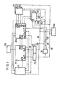
- FIG. 1 shows a possible structure of a microcomputer system with a DMA controller.
- the microprocessor MP and the DMA controller DMA is connected to one another via an internal bus IB for the transmission of data, addresses and control signals.
- An interruption controller US is assigned to the microprocessor MP, which supplies interrupt requests IT from the controller DMA or from other locations of the microcomputer system to the microprocessor MP in a processed form.
- the internal bus IB is connected via buffer ZW, bus driver BT to an external BU, which consists of an address bus AD, a data bus DB and a control bus SB.
- a memory MM, external devices P1, P2 and P3 are connected to the external bus BU.
- there is an interrupt and priority control UP on the external bus BU from which subchannels UK lead to slow peripheral devices PL.
- the clock required to operate the microcomputer system is output by a clock generator TGG.
- the control of the individual units of the microcomputer system by the microprocessor MP takes place via the control bus SB, in which the corresponding selection signal is generated from the addresses of the units to be controlled by a PROM module PRO.
- Access to the bus between the microcomputer MP 'and the controller DMA is determined by the signals HOLD and HLDA.
- the data transfer between e.g. the memory MM and the peripheral devices P1 to P3 is controlled by the controller DMA, with the help of operating requests DREQ from the peripheral devices and acknowledgment signals DACK from the controller DMA. Interruption requests between the peripheral devices P1 and P3 and the controller DMA are exchanged via signals EOD.
- Devices P1 to P3 are fast devices and the data transfer between these peripheral devices and e.g. the memory MM takes place in the selector mode.
- the interrupt control UP with which the slow peripheral devices PL are connected via subchannels UK, works with the control DMA with the help of operating instructions IOR and acknowledgment signals IOA on the operating requirements. If several peripheral devices PL make operating requests via several subchannels UK, the interrupt controller UP selects the highest priority peripheral device in accordance with the priorities of the peripheral devices PL and sends its operating request to the controller DMA. This acknowledges the operating request and initiates the desired data transfer between the peripheral device and, for example, the memory MM. Since the devices PL are slow devices, the data transfer between them and the data receiver or data transmitter can take place in multiplex mode.
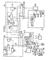
- the units shown in FIG. 1 are all commercially available modules except for the DMA controller, which is shown in more detail in FIG. 2.
- the DMA controller shown in FIG. 2 initially contains a known sequencer SE. This consists of a condition multiplexer CC, a command decoder MAP, a first multiplexer MUX1, a microaddress register MA, an address adder DR and a second multiplexer MUX2.
- the sequencer SE uses a command decoder MAP to generate the start address of the microprogram that is required to execute the channel command.
- These micro programs are stored in the MPS micro program memory.
- the microprogram memory MPS is connected to a microinstruction register MBR, in which the microinstructions issued are recorded. From there, the individual lines for control signals and addresses go to the other units of the DMA controller.
- the microinstruction register MBR is also connected to the sequencer SE, for example, in order to be able to develop the address of the next microinstruction to be processed from the previous microinstruction.
- sequencer SE for example, in order to be able to develop the address of the next microinstruction to be processed from the previous microinstruction.
- the address unit AU contains address register ADR for the channel command to be processed, for the data transmitter and data receiver. Since the contents, that is to say the addresses of the address register ADR, have to be changed, the address unit AU also contains an adder AD, in which quantities supplied by the microinstruction register MBR or other units of the DMA controller, for example, can be added to the contents contained in the address registers.
- the addresses of the address register ADR can be buffered in a buffer memory PS and then output on the address bus AB.
- the individual quantities which are added to the addresses in the adder AD are fed to the adder AD via a third multiplexer MUX 3 .
- the DMA controller also contains a data unit DU.
- the data unit DU is connected to the data bus DB.
- the data unit DU contains a buffer PS2, an input register EPS and an output register APS and a buffer memory DAR.
- the buffer memory DAR is located between the input register EPS and the output register APS and it serves to buffer the data to be transferred in the DMA controller.
- the commands to be processed in the DMA controller and the status of the channels are stored in registers of the control register set CR:
- the register set CR contains a channel command register CCR for receiving the channel command to be processed, a mode register GMR, a command register GCR for receiving the start command and a status register CSR for Takeover of the channel status after a transfer operation has ended.
- the registers CR are with the sequencer SE connected in the manner indicated in Figure 2.
- the DMA controller uses a byte counter BZ to determine how many bytes have been transferred during a transfer operation. Depending on the number of bytes transferred, the transfer operation can be ended. For this reason, the byte counter BZ is also connected to the sequencer SE. It is also connected to a circuit arrangement ITS for generating interrupt requests IT and EOD.
- the DMA controller also contains a priority logic PR, an adaptation circuit ANS for adapting the signals generated and received by the DMA controller. signals to the microprocessor MP or to the periphery and a clock generator TG.
- the individual units of the DMA controller are connected to one another via an internal data bus ID and an internal address and control bus IA.
- the external address bus AB can be connected to the internal address bus IA via a switch S1. This is necessary in order to be able to address the DMA registers for loading and reading from the microprocessor MP (e.g. loading the start command into the command register GCR).
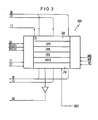
- FIG. 3 shows the structure of the address register ADR in the address unit AU.
- the address register set ADR there is an address register CPR for recording the address of the channel command, an address register SPR for recording the address of the data transmitter, an address register DPR for recording the address of the data receiver and an address register MTPR for recording an address part of the start address assigned to a subchannel for its channel program .
- An intermediate input register ZW is connected upstream of the address registers.
- the address registers for writing or reading are controlled via control signals from the internal address bus IA as a function of clock signals T1 and T2 from. Clock generator TG.
- the address of the to be described or the address register to be read is taken from the microinstruction register MBR and applied to the register set ADR. It is designated in Figure 2 and Figure 3 ARG.
- the DMA controller is informed of this by the microprocessor MP.
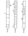
- a mode word is stored in the mode register GMR of the DMA controller, which contains a bit for identifying the operating mode. This bit sets the corresponding register position in the mode register GMR. Is this bit e.g. logical 0, then the selector mode is used, if logical 1, then the multiplex mode is used.
- the register GMR is shown and shown that e.g. the third register decides in which operating mode the data transmission takes place. The remaining parts of the mode register GMR are not required to explain the mode of data transmission and are therefore not shown.
- the decision as to whether the multiplex operation should be a byte multiplex operation or a block multiplex operation is made by the transfer command, which is stored in the channel command register CCR.
- the structure of such a transfer command is shown in FIG. 5.
- only the parts of the transfer command are shown that are required to explain the mode of data transmission.
- the component TL1 in the transfer command it is determined whether work is carried out in byte multiplex mode or in block multiplex mode. For example, if the part TL1 is logic 01, then it is working in byte multiplex mode, if it is logic 11, for example, then it is working in block multiplex mode.
- Part TL1 can also be used to code whether the command is a transfer command or a control command.
- the part TL2 of the transfer command indicates whether the data is transferred word by word or byte by byte, in which direction the data transfer is carried out and whether the address of the data receiver is increased or decreased. Accordingly, the part TL3 of the command indicates whether the address of the data transmitter is increased or decreased.
- the structure of the start command results from FIG. 6, which is stored in the command register GCR and with which a specific device is started or stopped.
- the command to be executed is specified in part TE1 of the command register GCR, e.g. the start command or the stop command, in part TE2 the channel is specified via which the data transfer is to be carried out, in part TE3 the address of the subchannel is specified via which the data transfer is to take place during multiplex operation.
- the DMA controller must be initialized before the first data transfer. This includes the loading of the mode register GMR and the address register ADR by the microprocessor MP. Before the data transfer is carried out, the microprocessor MP also stores the associated channel program in the memory MM. After this preparatory work, the microprocessor MP enters the start command for the subchannel UKO in the command register GCR of the DMA controller. This is step S1 in FIG. 7.
- step S2 the DMA controller according to FIG. 2 takes over the further processing of the start command.
- the DMA controller can see from the content of the mode register GMR that the data transmission is to take place in multiplex mode.
- the DMA controller accordingly sets an internal request INA, see step S2.
- the start command can only be executed when the multiplex channel has just finished processing, i.e. has entered the waiting state. Only then is the start processing started on the basis of the internal request INA (steps S3, S4 and S5).
- the address of the peripheral device PLO to be controlled results from the content of the command register GCR. There the address of the corresponding subchannel UKO is contained in part TE3, and in part TE1 it is also specified that the subchannel UKO or the device PLO connected to it is to be started.
- the DMA controller accordingly requests the subchannel UKO or the peripheral device PLO to start the data transmission and then, in a step S4 in FIG. 7, returns to the waiting state.
- This waiting state is ended when an operating request from the peripheral device PLO arrives at the DMA controller. This check is also shown in step S4 in FIG. 7. The waiting state remains until an operator request from the requested device arrives. During the waiting state, however, operating requests from other devices can be processed or other devices can be started via the multiplex channel. If the operating request arrives from the peripheral device PLO, then it is determined in a step S5 whether higher priority requests from other devices are not to be processed first (step S5). If this is not the case, the address of the requesting device is fetched in a step S6 and this address is temporarily stored in a device number register VRG.
- the address of the first channel command to be processed can be calculated in the memory MM. This is done with the aid of the adder AD, which has the device number and the via the multiplexer MUX3 Contents of the register MTPR is fed. The recalculated address is then output via the address bus AB and the first channel command is stored under this address in the channel command register CCR (step S7). In accordance with the channel command, the first data transfer of a byte or word is carried out (step S8) and then a check is carried out to determine whether the data transfer has ended (step S9).
- step S12 it is determined on the basis of the channel command in the channel command register CCR whether block multiplex operation is present or not.
- step S8 If block multiplex operation is present, then the process continues with step S8. If, on the other hand, there is byte multiplex operation, the transmission process is interrupted in step S13 and the wait state is returned to in step S14. In the case of byte multiplex operation, the process then continues with step S4.
- step S15 If the next channel command has been fetched in step S10, it is checked whether this is a control command (step S15). If the command is a transfer command, then proceed to step S14; however, if there is a control command, it is checked (step S16) whether it is a stop command. If this is the case, the processing of the channel program is ended and an interrupt IT is sent to the microprocessor MP give (step S17). If there is no stop command, the control command is executed (step S18) and the process continues with step S10.
- microinstructions which are stored in the microprogram memory MPS.
- the sequencer SE Depending on the channel command in the channel command register CCR and depending on the content of the mode register GMR, the sequencer SE generates the start address for the microprogram which is assigned to the channel command word by the command decoder MAP.
- the microprogram assigned to the channel command then runs under the control of the sequencer and the microinstructions issued by the microprogram memory MPS control the DMA control and the data transfer in the manner described above.
- a particular advantage of the invention is that the data transfer can be carried out in block multiplex operation or in byte multiplex operation by the DMA control, without large changes in the DMA control being necessary.
- the entire command initiation and command execution in block multiplex and byte multiplex are identical except for the execution of the data transfer, which in byte multiplex operation consists of only one byte, while in block multiplex operation an entire data block is transmitted.
Abstract
Description
Die Erfindung bezieht sich auf ein Verfahren zum Steuern eines Datentransfers von einem Datensender zu einem Datenempfänger über einen Bus mit Hilfe einer am Bus angeschlossenen Steuereinrichtung, die in Abhängigkeit eines Transferbefehle und Steuerbefehle enthaltenden Kanalprogramms den Datentransfer zwischen Datensender und Datenempfänger im Selektor-oder Multiplexbetrieb durchführt.The invention relates to a method for controlling a data transfer from a data transmitter to a data receiver via a bus with the aid of a control device connected to the bus which, depending on a channel program containing transfer commands and control commands, carries out the data transfer between the data transmitter and data receiver in the selector or multiplex mode.
Aus den DE-PS 23 39 813 und 23 39 787 ist es bekannt, daß Datentransfers zwischen einem Datensender, z. B. einem Speicher, und einem Datenempfänger, z.B. einem peripheren Gerät, bei einem Datenverarbeitungssystem mit Hilfe von sog. Kanalprogrammen durchgeführt wird. Die Kanalprogramme geben an, wie der Datentransfer durchzuführen ist, sie geben aber auch an, wie die organisatorischen Abläufe, wie Gerätestart, Gerätezustandsabfrage, Gerätestop, Unterbrechungsanforderung an die Recheneinheit usw. auszuführen sind. Die Kanalprogramme werden im Datenverarbeitungssystem dieser Art mit Hilfe von Kanalwerken durchgeführt, die zum Teil unabhängig von der Recheneinheit des Datenverarbeitungssystems den Datentransfer durchführen.From DE-PS 23 39 813 and 23 39 787 it is known that data transfers between a data transmitter, for. A memory and a data receiver, e.g. a peripheral device in a data processing system using so-called channel programs. The channel programs specify how the data transfer is to be carried out, but they also indicate how the organizational processes, such as device start, device status query, device stop, interrupt request to the computing unit, etc. are to be carried out. The channel programs are carried out in this type of data processing system with the help of channel works, some of which carry out the data transfer independently of the computing unit of the data processing system.
Die Kanalwerke von derartigen Großrechnern führen den Datentransfer entweder im Selektorbetrieb oder im Byte/WortMultiplexbetrieb durch. Die übertragungseinrichtungen, über die der Datentransfer erfolgt, werden im folgenden Kanäle genannt.The channel systems of such mainframes carry out the data transfer either in the selector mode or in the byte / word multiplex mode. The transmission devices via which the data transfer takes place are called channels below.
Selektorkanäle sind Hochgeschwindigkeitskanäle, die jeweils zu einer Zeit nur die Bearbeitung eines einzigen Il 1 The/27.10.1982 Kanalprogramms und damit die Bedienung eines einzigen peripheren Gerätes zulassen. Sind an einen Selektorkanal mehrere Geräte angeschlossen, so kann ein Wechsel von einem peripheren Gerät zu einem anderen erst nach gänzlicher Abarbeitung des ganzen Kanalprogramms, also erst beim nächsten Neustart des Selektorkanals vorgenommen werden. Beim Byte-Multiplexkanal dagegen kann nach jedem Byte-Transfer für ein Gerät ein Wechsel zu einem anderen Gerät vorgenommen werden. Dies setzt voraus, daß für jedes gestartete Gerät am Multiplexkanal auch ein Kanalprogramm vorhanden ist. Bei jeder peripheren Bedienungsanforderung muß der Multiplexkanal in Abhängigkeit z.B. der Gerätenummer oder . Unter kanal nummer auf das spezifische Kanalprogramm zusteuern, um de erforderlichen Bearbeitungsparameter zu erhalten. Da bei einem derartigen Verarbeitungssystem eine Vielzahl von einzelnen Geräten bedient werden muß, ist die Anzahl der Kanalprogramme groß, so daß diese im Hauptspeicher oder Systemspeicher abgespeichert werden müssen. Dann aber ist für jeden Bytetransfer die Ansteuerung des Kanalprogramms im Systemspeicher notwendig, mit der Folge, daß der Byte-Muliplex-/mit keinen hohen Transferraten arbeitet.Selector channels are high-speed channels, each processing only one Il 1 The / 27.10.1982 at a time Allow channel program and thus the operation of a single peripheral device. If several devices are connected to one selector channel, a change from one peripheral device to another can only be carried out after the entire channel program has been completely processed, i.e. only the next time the selector channel is restarted. With the byte multiplex channel, on the other hand, you can switch to another device after each byte transfer for one device. This presupposes that a channel program is also available for each started device on the multiplex channel. With each peripheral operating request, the multiplex channel must depend on, for example, the device number or. Navigate to the specific channel program under channel number in order to obtain the required processing parameters. Since a large number of individual devices must be operated in such a processing system, the number of channel programs is large, so that these must be stored in the main memory or system memory. Then, however, the channel program in the system memory must be activated for each byte transfer, with the result that the byte multiplex / does not work with high transfer rates.
Es ist nun weiterhin bekannt, die Datenübertragung im Blockmultiplexbetrieb durchzuführen..Ein Blockmultiplexkanal ist überall besonders vorteilhaft, wo an einem Kanal mehrere periphere Einheiten oder Geräte angeschlossen werden und bei den Geräten Wartezeiten eintreten können, nach denen aber der Datentransfer mit hoher Geschwindigkeit erfolgen muß. Beispiele für solche Geräte sind z.B. Plattenspeichergeräte oder Geräte, die mit einem Pufferspeicher ausgerüstet sind, in welchem die zu übertragenden Daten zunächst gesammelt werden, bevor sie übertragen werden. Der Vorteil des Blockmultiplexbetriebs besteht darin, daß die Wartezeiten der peripheren Geräte dazu verwendet werden können, Datentransferszu anderen oder von ande.ren Geräten auszuführen. Wie die Datenübertragung im Blockmultiplexbetrieb auszuführen ist, ergibt sich aus den oben angegebenen deutschen Patentschriften.It is now also known to carry out the data transmission in block multiplex operation. A block multiplex channel is particularly advantageous wherever several peripheral units or devices are connected to a channel and waiting times may occur for the devices, but after which the data transfer must take place at high speed. Examples of such devices are, for example, disk storage devices or devices which are equipped with a buffer memory in which the data to be transmitted are first collected before they are transmitted. The advantage of block multiplexing is that the waiting times of the peripheral devices can be used to transfer data to or from others other devices. How the data transmission in block multiplex operation is to be carried out results from the above-mentioned German patent specifications.
Die Steuerung des Datentransfers zwischen einem Datensender und einem Datenempfänger kann auch mit Hilfe von Mikrocomputersystemen erfolgen. Solche Mikrocomputersysteme enthalten in der Regel einen Mikrocomputer, einen Speicher und periphere Geräte, die entweder direkt oder über Zwischeneinheiten mit einem Bus verbunden sind. über den Bus erfolgt dann die Übertragung der Adressen, der Daten und der Steuersignale. Die Steuerung des Datentransfers z.B. zwischen dem Speicher und einem peripheren Gerät wird vom Mikrocomputer in Abhängigkeit des sog. Kanalprogramms gesteuert. Um den Mikrocomputer von der Steuerung 'zu entlasten, ist es bekannt, zusätzlich an den Bus z.B. eine DMA Steuerung anzuschließen, die den Datentransfer unabhängig vom Mikrocomputer steuert. Während die DMA Steuerung den Datentransfer durchführt, kann dann der Mikrocomputer andere Aufgaben erledigen. Ein derartiges System ergibt sich z.B. aus "Elektronik Praxis", Nr. 9, Sept. 1982, S. 131 - 134.The control of the data transfer between a data transmitter and a data receiver can also be carried out with the aid of microcomputer systems. Such microcomputer systems typically include a microcomputer, memory, and peripheral devices that are connected to a bus either directly or through intermediate units. The addresses, data and control signals are then transmitted via the bus. The control of the data transfer, for example between the memory and a peripheral device, is controlled by the microcomputer in dependence on the so-called channel program. In order to relieve the microcomputer from the controller ', it is known to additionally include a DMA controller to the bus, for example, which controls the data transfer independently of the microcomputer. The microcomputer can then perform other tasks while the DMA controller is performing the data transfer. Such a system results, for example, from "Electronics Practice", No. 9, Sept. 1982, pp. 131-134.
Die der Erfindung zugrundeliegende Aufgabe besteht darin, ein Verfahren anzugeben, bei dem eine Steuereinrichtung, z.B. eine DMA Steuerung, den Datentransfer zwischen einem Datensender und einem Datenempfänger in einem der drei Betriebsarten durchführen kann, also den dazu verwendeten Kanal entweder im Selektorbetrieb, Bytemultiplexbetrieb oder Blockmultiplexbetrieb benutzt. Diese Aufgabe wird bei einem Verfahren der eingangs angegebenen Art dadurch gelöst, daß die Umschaltung zwischen Selektorbetrieb und Multiplexbetrieb durch den Inhalt einer Registerstell.e in einem Modusregister der Steuereinrichtung festgelegt wird und daß bei Umschaltung in den Multiplexbetrieb die Datenübertragung im Byte/Wortmultiplexbetrieb oder Blockmultiplexbetrieb erfolgt.The object on which the invention is based is to specify a method in which a control device, for example a DMA controller, can carry out the data transfer between a data transmitter and a data receiver in one of the three operating modes, that is to say the channel used for this purpose either in selector operation, byte multiplex operation or block multiplex operation used. This object is achieved in a method of the type mentioned above in that the switchover between selector operation and multiplex operation is determined by the content of a register position in a mode register of the control device and that the data is switched over in the multiplex operation Transmission takes place in byte / word multiplex mode or block multiplex mode.
Ob der Kanal im Blockmultiplexbetrieb oder Bytemultiplexbetrieb arbeitet, wird mit Hi.Ife des im Kanalprogramm enthaltenen Transferbefehls festgelegt. Da somit mit dem Kanal sowohl im Bytemultiplexbetrieb als auch im Blockmultiplexbetrieb gearbeitet werden kann, ist es zweckmäßig, die Abarbeitung des entsprechenden Transferbefehls bei beiden Betriebsarten möglichst identisch zu gestalten. Identisch ist die organisatorische Bearbeitung eines Transferbefehls in beiden Betriebsarten in folgenden Schritten: Starten eines Gerätes oder Unterkanals,an dem das Gerät angeschlossen ist, dabei kann die Startoperation zwischen zwei Datentransfers anderer Unterkanäle eingeschoben werden. Anschließend geht der neu aktivierte Unterkanal in Warteposition.Whether the channel works in block multiplex operation or byte multiplex operation is determined with Hi.Ife of the transfer command contained in the channel program. Since the channel can thus be used both in byte multiplex operation and in block multiplex operation, it is expedient to make the processing of the corresponding transfer command as identical as possible in both operating modes. The organizational processing of a transfer command in both operating modes is identical in the following steps: Starting a device or subchannel to which the device is connected, the start operation can be inserted between two data transfers from other subchannels. The newly activated subchannel then waits.
Trifft nun an der Steuereinrichtung eine Garäteanforderung des neu gestarteten Gerätes ein, so wird im Gegensatz zum Bytemultiplexbetrieb, bei dem nur ein einziges Byte übertragen wird und anschließend wieder der Wartezustand eingenommen wird, beim Blockmultiplexbetrieb der gesamte Blocktransfer ausgeführt. Das heißt auf eine einzige Bedienungsanforderung erfolgt ein ganzer Blocktransfer. Wie beim Bytemultiplexkanal oder Selektorkanal erfolgt nach dem übertragen des letzten Datums des Blockes automatisch eine Befehlskettung, so daß der nächste Kanalbefehl im Kanalprogramm bearbeitet wird. Der nächste Kanalbefehl kann dabei ein Steuerbefehl oder wiederum ein Transferbefehl sein.If a device request for the newly started device arrives at the control device, in contrast to byte multiplex operation, in which only a single byte is transmitted and then the waiting state is restored, the entire block transfer is carried out in block multiplex operation. This means that an entire block transfer takes place on a single operating request. As with the byte multiplex channel or selector channel, a command chain is automatically sent after the last date of the block has been transmitted, so that the next channel command is processed in the channel program. The next channel command can be a control command or a transfer command.
Wie beim Bytemultiplexkanal, so wird auch am Blockmultiplexkanal der Wartezustand des Unterkanals wieder eingenommen, sobald bei der Befehlskettung im Kanalprogramm ein Transferbefehl erkannt wird. Erst eine erneute Bedienungsanforderung des gestarteten Gerätes initiiert den nächsten Blocktransfer.As with the byte multiplex channel, the waiting state of the subchannel is also resumed on the block multiplex channel as soon as the command chain in the channel program Transfer command is recognized. The next block transfer is not initiated until the started device is requested again.
Wartezeiten zwischen dem Starten des Gerätes und der ersten Bedienungsanforderung können jederzeit zur Bearbeitung von Bedienungsanforderungen anderer Unterkanäle ausgenutzt werden.Waiting times between starting the device and the first operating request can be used at any time to process operating requests from other subchannels.
Jede Anforderungsbearbeitung beginnt mit der Abfrage der Adresse des Detenempfängers, z.B. der Abfrage der Gerätenummer oder der Nummer des Unterkanals. Mit dieser Adresse wird denn z.B. über eine Tabelle im Speicher auf das spezifische Kanalprogramm zugegriffen.Each request processing begins with the query of the address of the recipient, e.g. the query of the device number or the number of the subchannel. With this address e.g. The specific channel program is accessed via a table in the memory.
Andere Weiterbildungen der Erfindung ergeben sich aus den Unteransprüchen.Other developments of the invention result from the subclaims.
An Hand eines Ausführungsbeispiels, das in den Figuren dargestellt ist, wird die Erfindung weiter erläutert. Es zeigen
- Figur 1 ein Blockschaltbild eines Mikrocomputersystems mit einer DMA Steuerung,
- Figur 2 den Aufbau der DMA Steuerung,
- Figur 3 eine ausführlichere Darstellung eines Teils der DMA Steuerung,
- Figur 4 den Aufbau eines Modusregisters,
Tigur 5 der Aufbau eines Transferbefehls,- Figur 6 den Aufbau eines Befehlsregisters,
Figur 7 ein Ablaufdiagramm, in dem die einzelnen Bearbeitungsschritte bei einem Blockmultiplexkanal dargestellt sind.
- FIG. 1 shows a block diagram of a microcomputer system with a DMA controller,
- FIG. 2 shows the structure of the DMA controller,
- FIG. 3 shows a more detailed representation of part of the DMA controller,
- FIG. 4 shows the structure of a mode register,
- Tigur 5 the structure of a transfer command,
- FIG. 6 shows the structure of a command register,
- Figure 7 is a flowchart showing the individual processing steps in a block multiplex channel.
Figur 1 zeigt einen möglichen Aufbau eines Mikrocomputersystems mit einer DMA Steuerung. Der Mikroprosessor MP und die DMA Steuerung DMA ist über einen internen Bus IB zur Übertragung von Daten, Adressen und Steuersignale miteinander verbunden. Dem Mikroprozessor MP ist eine Unterbrechungssteuerung US zugeordnet, die Unterbrechungsanforderungen IT von der Steuerung DMA bzw. von anderen Stellen des Mikrocomputersystems in aufbereiteter Form dem Mikroprozessor- MP zuführt. Der interne Bus IB ist über Zwischenspeicher ZW, Bustreiber BT mit einem externen BU verbunden, der aus einem Adreßbus AD, einem Datenbus DB und einem Steuerbus SB besteht. An dem externen Bus BU sind ein Speicher MM, externe Geräte P1, P2 und P3 angeschlossen. Zu dem liegt am externen Bus BU eine Unterbrechungs- und Prioritätssteuerung UP, von der aus Unterkanäle UK zu langsamen peripheren Geräten PL führen. Der zum Betrieb des Mikrocomputersystems erforderliche Takt wird durch einen Taktgenerator TGG abgegeben.Figure 1 shows a possible structure of a microcomputer system with a DMA controller. The microprocessor MP and the DMA controller DMA is connected to one another via an internal bus IB for the transmission of data, addresses and control signals. An interruption controller US is assigned to the microprocessor MP, which supplies interrupt requests IT from the controller DMA or from other locations of the microcomputer system to the microprocessor MP in a processed form. The internal bus IB is connected via buffer ZW, bus driver BT to an external BU, which consists of an address bus AD, a data bus DB and a control bus SB. A memory MM, external devices P1, P2 and P3 are connected to the external bus BU. In addition, there is an interrupt and priority control UP on the external bus BU, from which subchannels UK lead to slow peripheral devices PL. The clock required to operate the microcomputer system is output by a clock generator TGG.
Die Ansteuerung der einzelnen Einheiten des Mikrocomputersystems durch den Mikroprozessor MP erfolgt über den Steuerbus SB, bei den ausgehend von Adressen der anzusteuernden Einheiten durch einen PROM-Baustein PROdas entsprechende Auswahlsignal erzeugt wird. Der Zugriff zum Bus zwischen dem Mikrocomputer MP'und der Steuerung DMA wird durch die Signale HOLD und HLDA festgelegt. Der Datentransfer zwischen z.B. dem Speicher MM und den-peripheren Geräten P1 bis P3 wird durch die Steuerung DMA gesteuert und zwar mit Hilfe von Bedienungsanforderungen DREQ von den peripheren Geräten und Quittungssignalen DACK von der Steuerung DMA. Unterbrechungsanforderungen zwischen denperipheren Geräten P1 und P3 und der Steuerung DMA werden über Signale EOD ausgetauscht. Die Geräte P1 bis P3 sind schnelle Geräte und der Datentransfer zwischen diesen peripheren Geräten und z.B. dem Speicher MM erfolgt im Selektorbetrieb.The control of the individual units of the microcomputer system by the microprocessor MP takes place via the control bus SB, in which the corresponding selection signal is generated from the addresses of the units to be controlled by a PROM module PRO. Access to the bus between the microcomputer MP 'and the controller DMA is determined by the signals HOLD and HLDA. The data transfer between e.g. the memory MM and the peripheral devices P1 to P3 is controlled by the controller DMA, with the help of operating requests DREQ from the peripheral devices and acknowledgment signals DACK from the controller DMA. Interruption requests between the peripheral devices P1 and P3 and the controller DMA are exchanged via signals EOD. Devices P1 to P3 are fast devices and the data transfer between these peripheral devices and e.g. the memory MM takes place in the selector mode.
Die Unterbrechungssteuerung UP, mit der die langsamen peripheren Geräte PL über Unterkanäle UK verbunden sind, arbeitet mit der Steuerung DMA mit Hilfe von Bedienungsanforderungen IOR und Quittungssignalen IOA auf die Bedienungsanforderungen zusammen. Wenn mehrere periphere Geräte PL über mehrere Unterkanäle UK Bedienungsanforderungen stellen, dann wählt die Unterbrechungssteuerung UP entsprechend den Prioritäten der peripheren Geräte PL das höchstpriore periphere Gerät aus und gibt dessen Bedienungsanforderung an die Steuerung DMA. Diese quittiert die Bedienungsanforderung und leitet den gewünschten Datentransfer zwischen dem peripheren Gerät und z.B. dem Speicher MM ein. Da die Geräte PL langsame Geräte sind, kann der Datentransfer zwischen ihnen und dem Datenempfänger bzw. Datensender im Multiplexbetrieb erfolgen.The interrupt control UP, with which the slow peripheral devices PL are connected via subchannels UK, works with the control DMA with the help of operating instructions IOR and acknowledgment signals IOA on the operating requirements. If several peripheral devices PL make operating requests via several subchannels UK, the interrupt controller UP selects the highest priority peripheral device in accordance with the priorities of the peripheral devices PL and sends its operating request to the controller DMA. This acknowledges the operating request and initiates the desired data transfer between the peripheral device and, for example, the memory MM. Since the devices PL are slow devices, the data transfer between them and the data receiver or data transmitter can take place in multiplex mode.
Die in Figur 1 gezeigten Einheiten sind alles handelsübliche Bausteine bis auf die Steuerung DMA, die in Figur 2 ausführlicher dargestellt ist.The units shown in FIG. 1 are all commercially available modules except for the DMA controller, which is shown in more detail in FIG. 2.
Die in Figur 2 gezeigte DMA Steuerung enthält zunächst einen Sequencer SE bekannten Aufbaus. Dieser besteht aus einem Bedingungsmultiplexer CC, einem Befehlsdecoder MAP, einem ersten Multiplexer MUX1, einem Mikroadressenregister MA, einem Adreßaddierer DR und einem zweiten Multiplexer MUX2. Der Sequencer SE erzeugt aus einem Kanalbefehl mit Hilfe des Befehlsdecoders MAP die Startadresse des Mikroprogramms, das zur Ausführung des Kanalbefehls erforderlich ist. Diese Mikroprogramme stehen im Mikroprogrammspeicher MPS. Der Mikroprogrammspeicher MPS ist mit einem Mikrobefehlsregister MBR verbunden, in den die ausgegebenen Mikrobefehle aufgenommen werden. Von dort aus gehen dann die einzelnen Leitungen für Steuersignale und Adressen zu den übrigen Einheiten der DMA Steuerung. Das Mikrobefehlsregister MBR ist z.B. auch mit dem Sequencer SE verbunden, um aus dem vorhergehenden Mikrobefehl die Adresse des nächst zu bearbeitenden Mikrobefehls entwickeln zu können. Der Aufbau eines Sequencers SE und das Zusammenspiel mit den genannten Einheiten ergibt sich z.B. aus der oben angegenbenen Literaturstelle "Elektronik Praxis".The DMA controller shown in FIG. 2 initially contains a known sequencer SE. This consists of a condition multiplexer CC, a command decoder MAP, a first multiplexer MUX1, a microaddress register MA, an address adder DR and a second multiplexer MUX2. The sequencer SE uses a command decoder MAP to generate the start address of the microprogram that is required to execute the channel command. These micro programs are stored in the MPS micro program memory. The microprogram memory MPS is connected to a microinstruction register MBR, in which the microinstructions issued are recorded. From there, the individual lines for control signals and addresses go to the other units of the DMA controller. The microinstruction register MBR is also connected to the sequencer SE, for example, in order to be able to develop the address of the next microinstruction to be processed from the previous microinstruction. The construction of a SE sequencer and the interaction with the units mentioned result, for example, from the above-mentioned literature "Electronics Practice".
Eine weitere Einheit der DMA Steuerung ist die Adress neinheit AU. Diese enthält Adressenregister ADR für den abzuarbeitenden Kanalbefehl, für den Datensender und Datenempfänger. Da die Inhalte, also die Adressen der Adressenregister ADR verändert werden müssen, enthält die Adresseneinheit AU weiterhin einen Addierer AD, in dem zu der in den Adressenregistern enthaltenen Inhalten z.B. vom Mikrobefehlsregister MBR oder von anderen Einheiten der DMA Steuerung gelieferte Größen hinzuaddiert werden können. Die Adressen der Adressenregister ADR können in einem Pufferspeicher PS zwischengespeichert werden und dann auf den Adreßbus AB ausgegeben werden. Die einzelnen Größen, die zu den Adressen im Addierer AD hinzuaddiert werden, werden über einen dritten Mulitplexer MUX3dem Addierer AD zugeführt.Another unit of the DMA controller is the address unit AU. This contains address register ADR for the channel command to be processed, for the data transmitter and data receiver. Since the contents, that is to say the addresses of the address register ADR, have to be changed, the address unit AU also contains an adder AD, in which quantities supplied by the microinstruction register MBR or other units of the DMA controller, for example, can be added to the contents contained in the address registers. The addresses of the address register ADR can be buffered in a buffer memory PS and then output on the address bus AB. The individual quantities which are added to the addresses in the adder AD are fed to the adder AD via a third multiplexer MUX 3 .
Die DMA Steuerung enthält weiterhin eine Dateneinheit DU. Die Dateneinheit DU ist mit dem Datenbus DB verbunden. Die Dateneinheit DU enthält einen Zwischenspeicher PS2, ein Eingangsregister EPS und ein Ausgangsregister APS und einen Pufferspeicher DAR. Der Pufferspeicher DAR liegt zwischen dem Eingangsregister EPS und dem Ausgangsregister APS und er dient dazu, die zu übertragenden Daten in der DMA Steuerung zwischenspeichernzu können.The DMA controller also contains a data unit DU. The data unit DU is connected to the data bus DB. The data unit DU contains a buffer PS2, an input register EPS and an output register APS and a buffer memory DAR. The buffer memory DAR is located between the input register EPS and the output register APS and it serves to buffer the data to be transferred in the DMA controller.
Die in der DMA Steuerung abzuarbeitenden Befehle und der Status der Kanäle sind in Registern des Steuerregistersatzes CR abgespeichert: Der Registersatz CR enthält ein Kanalbefehlsregister CCR zur Aufnahme des zu bearbeitenden Kanalbefehls, ein Modusregister GMR, ein Befehlsregister GCR zur Aufnahme des Startbefehls und ein Statusregister CSR zur übernahme des Kanalstatus nach Beendigung einer Transferoperation. Die Register CR sind mit dem Sequencer SE in der in Figur 2 angegebenen Weise verbunden.The commands to be processed in the DMA controller and the status of the channels are stored in registers of the control register set CR: The register set CR contains a channel command register CCR for receiving the channel command to be processed, a mode register GMR, a command register GCR for receiving the start command and a status register CSR for Takeover of the channel status after a transfer operation has ended. The registers CR are with the sequencer SE connected in the manner indicated in Figure 2.
Mit Hilfe eines Bytezählers BZ stellt die DMA Steuerung fest, wieviel Byte bei einer Transferoperation übertragen worden sind. In Abhängigkeit der Anzahl der übertragenen Byte kann die Transferoperation beendet werden. Aus diesem Grunde ist der Bytezähler BZ auch mit dem Sequencer SE verbunden. Er ist ebenfalls mit einer Schaltungsanordnung ITS zur Erzeugung von Unterbrechungsanforderungen IT und EOD verbunden.The DMA controller uses a byte counter BZ to determine how many bytes have been transferred during a transfer operation. Depending on the number of bytes transferred, the transfer operation can be ended. For this reason, the byte counter BZ is also connected to the sequencer SE. It is also connected to a circuit arrangement ITS for generating interrupt requests IT and EOD.
Schließlich enthält die DMA Steuerung noch eine Prioritätslogik PR, eine Anpassungsschaltung ANS zur Anpassung der von der DMA Steuerung erzeugten und entgegengenommenen Sig- . nale an den Mikroprozessor MP bzw. an die Peripherie und einen Taktgenerator TG.Finally, the DMA controller also contains a priority logic PR, an adaptation circuit ANS for adapting the signals generated and received by the DMA controller. signals to the microprocessor MP or to the periphery and a clock generator TG.
Die einzelnen Einheiten der DMA Steuerung sind über einen internen Datenbus ID und einen internen Adreß- und Steuerbus IA miteinander verbunden. Über einen Schalter S1 kann der externe Adreßbus AB mit dem internen Adreßbus IA verbunden werden. Dies ist erforderlich, um die DMA-Register zum Laden und Lesen vom Mikroprozessor MP aus adressieren zu können (z.B. Laden des Startbefehls in das Befehlsregister GCR).The individual units of the DMA controller are connected to one another via an internal data bus ID and an internal address and control bus IA. The external address bus AB can be connected to the internal address bus IA via a switch S1. This is necessary in order to be able to address the DMA registers for loading and reading from the microprocessor MP (e.g. loading the start command into the command register GCR).
Aus Figur 3 ergibt sich der Aufbau des Adressenregisters ADR in der Adresseneinheit AU. Im Adressenregistersatz ADR ist ein Adressenregister CPR zur Aufnahme der Adresse des Kanalbefehls, ein Adressenregister SPR zur Aufnahme der Adresse des Datensenders, ein Adressenregister DPR zur Aufnahme der Adresse des Datenempfängers und ein Adressenregister MTPR zur Aufnahme eines Adreßteils der einem Unterkanal zugeordenthalten neten Startadresse für dessen Kanalprogramm. Den Adressenregistern ist ein Eingangszwischenregister ZW vorgeschaltet. Die Ansteuerung der Adressenregister zum Schreiben oder zum Lesen erfolgt über Steuersignale vom internen Adreßbus IA in Abhängigkeit von Taktsignalen T1 und T2 vom . Taktgenerator TG. Die Adresse des zu beschreibenden oder zu lesenden Adreßregisters wird dem Mikrobefehlsregister MBR entnommen und an den Registersatz ADR angelegt. Sie ist in Figur 2 und Figur 3 ARG bezeichnet.3 shows the structure of the address register ADR in the address unit AU. In the address register set ADR there is an address register CPR for recording the address of the channel command, an address register SPR for recording the address of the data transmitter, an address register DPR for recording the address of the data receiver and an address register MTPR for recording an address part of the start address assigned to a subchannel for its channel program . An intermediate input register ZW is connected upstream of the address registers. The address registers for writing or reading are controlled via control signals from the internal address bus IA as a function of clock signals T1 and T2 from. Clock generator TG. The address of the to be described or the address register to be read is taken from the microinstruction register MBR and applied to the register set ADR. It is designated in Figure 2 and Figure 3 ARG.
Soll der Datentransfer zwischen dem Datensender und dem Datenempfänger im Multiplexbetrieb durchgeführt werden, also über die Unterbrechungssteuerung UP in Figur 1, dann wird dies der DMA Steuerung vom Mikroprozessor MP mitgeteilt. Dazu wird in das Modusregister GMR der DMA Steuerung ein Moduswort eingespeichert, bei dem ein Bit zur Kennzeichnung der Betriebsart enthalten ist. Durch dieses Bit wird die entsprechende Registerstelle im Modusregister GMR eingestellt. Ist dieses Bit z.B. logisch 0, dann wird im Selektorbetrieb gearbeitet, ist es logisch 1, dann wird im Multiplexbetrieb gearbeitet. In Figur 4 ist das Register GMR dargestellt und gezeigt, daß z.B. die dritte Registerstelle darüber entscheidet, in welch-er Betriebsart die Datenübertragung erfolgt. Die übrigen Teile des Modusregisters GMR sind zur Erläuterung der Betriebsart der Datenübertragung nicht erforderlich und sind darum nicht dargestellt.If the data transfer between the data transmitter and the data receiver is to be carried out in multiplex mode, that is to say via the interrupt controller UP in FIG. 1, the DMA controller is informed of this by the microprocessor MP. For this purpose, a mode word is stored in the mode register GMR of the DMA controller, which contains a bit for identifying the operating mode. This bit sets the corresponding register position in the mode register GMR. Is this bit e.g. logical 0, then the selector mode is used, if logical 1, then the multiplex mode is used. In figure 4 the register GMR is shown and shown that e.g. the third register decides in which operating mode the data transmission takes place. The remaining parts of the mode register GMR are not required to explain the mode of data transmission and are therefore not shown.
Die Entscheidung darüber, ob der Multiplexbetrieb ein Bytemultiplexbetrieb oder ein Blockmültiplexbetrieb sein soll, trifft der Transferbefehl, der im Kanalbefehlsregister CCR abgespeichert wird. Der Aufbau eines derartigen Transferbefehls zeigt Figur 5. Auch hier sind nur die Teile des Transferbefehls dargestellt, die zur Erläuterung der Betriebsart der Datenübertragung erforderlich sind. Mit Hilfe des Bestandteils TL1 im Transferbefehl wird festgelegt, ob im Bytemultiplexbetrieb oder im Blockmultiplexbetrieb gearbeitet wird. Ist z.B. der Teil TL1 logisch 01, dann wird im Bytemultiplexbetrieb gearbeitet, ist er z.B. logisch 11, dann wird im Blockmultiplexbetrieb gearbeitet. Mit Hilfe des TeilsTL1 kann außerdem codiert werden, ob der Befehl ein Transferbefehl ist oder ein Steuerbefehl. Der Teil TL2 des Transferbefehls gibt an, ob die Übertragung der Daten wortweise oder byteweise erfolgt, in welcher Richtung der Datentransfer durchgeführt wird und ob die Adresse des Datenempfängers erhöht oder erniedrigt wird. Entsprechend gibt der Teil TL3 des Befehls an, ob die Adresse des Datensenders erhöht oder erniedrigt wird.The decision as to whether the multiplex operation should be a byte multiplex operation or a block multiplex operation is made by the transfer command, which is stored in the channel command register CCR. The structure of such a transfer command is shown in FIG. 5. Here, too, only the parts of the transfer command are shown that are required to explain the mode of data transmission. With the help of the component TL1 in the transfer command, it is determined whether work is carried out in byte multiplex mode or in block multiplex mode. For example, if the part TL1 is logic 01, then it is working in byte multiplex mode, if it is logic 11, for example, then it is working in block multiplex mode. Part TL1 can also be used to code whether the command is a transfer command or a control command. The part TL2 of the transfer command indicates whether the data is transferred word by word or byte by byte, in which direction the data transfer is carried out and whether the address of the data receiver is increased or decreased. Accordingly, the part TL3 of the command indicates whether the address of the data transmitter is increased or decreased.
Aus Figur 6 ergibt sich der Aufbau des Startbefehls, der in das Befehlsregister GCR eingespeichert wird und mit dem ein bestimmtes Gerät gestartet oder gestoppt wird. In einem Teil TE1 des Befehlsregisters GCR ist der auszuführende Befehl angegeben, z.B. der Startbefehl oder der Stoppbefehl, in einem Teil TE2 ist der Kanal angegeben, über den der Datentransfer durchzuführen ist, in einem Teil TE3 ist die Adresse des Unterkanals angegeben, über die beim Multiplexbetrieb der Datentransfer erfolgen soll.The structure of the start command results from FIG. 6, which is stored in the command register GCR and with which a specific device is started or stopped. The command to be executed is specified in part TE1 of the command register GCR, e.g. the start command or the stop command, in part TE2 the channel is specified via which the data transfer is to be carried out, in part TE3 the address of the subchannel is specified via which the data transfer is to take place during multiplex operation.
Im folgenden wird in Verbindung mit dem Ablaufdiagramm der Figur 7 beschrieben, wie der Multiplexbetrieb bei der Datenübertragung z.B. zwischen dem Speicher MM und dem peripheren Gerät PLO über den Unterkanal UKO nach Figur 1 durchgeführt wird. Vor dem ersten Datentransfer muß die DMA-Steuerung initialisiert werden. Dazu gehört das. Laden des Modusregisters GMR und des Adreßregisters ADR durch den Mikroprozessor MP. Vor der Ausführung des Datentransfers hinterlegt der Mikroprozessor MP auch das zugehörige Kanalprogramm im Speicher MM. Nach dieser Vorarbeit trägt der Mikroprozessor MP den Startbefehl für den Unterkanal UKO in das Befehlsregister GCR der DMA-Steuerung ein. Dies ist der Schritt S1 in Figur 7.In the following it is described in connection with the flow diagram of FIG. 7 how the multiplex operation during data transmission e.g. is carried out between the memory MM and the peripheral device PLO via the subchannel UKO according to FIG. The DMA controller must be initialized before the first data transfer. This includes the loading of the mode register GMR and the address register ADR by the microprocessor MP. Before the data transfer is carried out, the microprocessor MP also stores the associated channel program in the memory MM. After this preparatory work, the microprocessor MP enters the start command for the subchannel UKO in the command register GCR of the DMA controller. This is step S1 in FIG. 7.
Im-Schritt S2 übernimmt die DMA-Steuerung nach Figur 2 die weitere Bearbeitung des Startbefehls. Aus dem Inhalt des Modusregisters GMR kann die DMA Steuerung entnehmen, daß die Datenübertragung im Multiplexbetrieb erfolgen soll.In step S2, the DMA controller according to FIG. 2 takes over the further processing of the start command. The DMA controller can see from the content of the mode register GMR that the data transmission is to take place in multiplex mode.
Entsprechend setzt die DMA Steuerung eine interne Anforderung INA, siehe Schritt S2. Der Startbefehl kann erst dann zur Ausführung kommen, wenn der Multiplexkanal eine gerade laufende Bearbeitung beendet hat,also den Wartezustand eingenommen hat. Erst dann wird auf Grund der internen Anforderung INA die Startbearbeitung aufgenommen ( Schritt S3,S4 und S5). Die Adresse des anzusteuernden peripheren Gerätes PLO ergibt sich aus dem Inhalt des Befehlsregisters GCR. Dort ist die Adresse des entsprechenden Unterkanals UKO im Teil TE3 enthalten, außerdem im Teil TE1 angegeben, daß der Unterkanal UKO bzw. das daran angeschlossene Gerät PLO gestartet werden soll. Die DMA Steuerung gibt dementsprechend eine Aufforderung an den Unterkanal UKO bzw. das periphere Gerät PLO, die Datenübertragung zu beginnen und geht dann,in einem Schritt S4 der Figur 7 wieder in den Wartezustand über. Dieser Wartezustand wird dann beendet, wenn eine Bedienungsanforderung vom peripheren Gerät PLO bei der DMA Steuerung eintrifft. Diese überprüfung wird ebenfalls in Schritt S4 in Figur 7 dargestellt. Der Wartezustand bleibt solange erhalten, bis eine Bedienungsaufforderung von dem aufgeforderten Gerät eintrifft. Während des Wartezustandes können jedoch Bedienungsanforderungen von anderen Geräten bearbeitet werden bzw. andere Geräte über den Multiplexkanal gestartet werden. Trifft vom peripheren Gerät PLO die Bedienungsanforderung ein, dann wird in einem Schritt S5 festgestellt, ob nicht höherpriore Anforderungen von anderen Geräten zunächst zu bearbeiten sind (Schritt S5). Ist dies nicht der Fall, dann wird in einem Schritt S6 die Adresse des anfordernden Gerätes geholt und diese Adresse in einem Gerätenummernregister VRG zwischengespeichert. Mit Hilfe dieser Gerätenummer aus dem Gerätenummernregister VRG und dem Inhalt des Adressenregisters MTPR kann die Adresse des ersten zu bearbeitenden Kanalbefehls im Speicher MM berechnet werden. Dies erfolgt mit Hilfe des Addierers AD, dem über den Multiplexer MUX3 die Gerätenummer und der Inhalt des Registers MTPR zugeführt wird. Die neuberechnete Adresse wird dann über den Adreßbus AB ausgegeben und unter dieser Adresse der erste Kanalbefehl in das Kanalsbefehlsregister CCR eingespeichert (Schritt S7). Entsprechend dem Kanalbefehl wird die erste Datenübertragung eines Bytes oder Wortes durchgeführt (Schritt S8) und anschließend überprüft, ob die Datenübertragung beendet ist (Schritt S9). Dies erfolgt mit Hilfe des Bytezählers BZ, der von der DMA Steuerung aus dem Kanalbefehl geladen worden ist und der die Anzahl der zu übertragenden Bytes oder Worte angibt. Sind alle Daten für diesen Datentransferbefehl übertragen worden, dann ist dieser Kanalbefehl abgearbeitet worden und der nächste Kanalbefehl wird in einem Schritt S10 aus dem Speicher MM geholt. Ist dagegen die Datenübertragung, die durch einen Transferbefehl durchgeführt, werden soll, noch nicht beendet,' wird in einem Schritt S11 abgefragt, ob ein anderer Grund zur Beendigung der Datenübertragung vorliegt, z.B. eine Unterbrechungsanforderung des peripheren Geräts vorliegt. Ist dies nicht der Fall, dann wird anhand des Kanalbefehls im Kanalbefehlsregister CCR festgestellt, ob Blockmultiplexbetrieb vorliegt oder nicht (Schritt S12). Liegt Blockmultiplexbetrieb vor, dann wird mit dem Schritt S8 fortgefahren. Liegt dagegen ein Bytemultiplexbetrieb vor, dann wird in einem Schritt S13 der übertragungsvorgang unterbrochen und im Schritt S14 wieder in den Wartezustand übergegangen. Beim Bytemultiplexbetrieb wird dann mit Schritt S4 fortgefahren.The DMA controller accordingly sets an internal request INA, see step S2. The start command can only be executed when the multiplex channel has just finished processing, i.e. has entered the waiting state. Only then is the start processing started on the basis of the internal request INA (steps S3, S4 and S5). The address of the peripheral device PLO to be controlled results from the content of the command register GCR. There the address of the corresponding subchannel UKO is contained in part TE3, and in part TE1 it is also specified that the subchannel UKO or the device PLO connected to it is to be started. The DMA controller accordingly requests the subchannel UKO or the peripheral device PLO to start the data transmission and then, in a step S4 in FIG. 7, returns to the waiting state. This waiting state is ended when an operating request from the peripheral device PLO arrives at the DMA controller. This check is also shown in step S4 in FIG. 7. The waiting state remains until an operator request from the requested device arrives. During the waiting state, however, operating requests from other devices can be processed or other devices can be started via the multiplex channel. If the operating request arrives from the peripheral device PLO, then it is determined in a step S5 whether higher priority requests from other devices are not to be processed first (step S5). If this is not the case, the address of the requesting device is fetched in a step S6 and this address is temporarily stored in a device number register VRG. With the help of this device number from the device number register VRG and the content of the address register MTPR, the address of the first channel command to be processed can be calculated in the memory MM. This is done with the aid of the adder AD, which has the device number and the via the multiplexer MUX3 Contents of the register MTPR is fed. The recalculated address is then output via the address bus AB and the first channel command is stored under this address in the channel command register CCR (step S7). In accordance with the channel command, the first data transfer of a byte or word is carried out (step S8) and then a check is carried out to determine whether the data transfer has ended (step S9). This is done with the help of the byte counter BZ, which has been loaded from the channel command by the DMA controller and which indicates the number of bytes or words to be transferred. If all data for this data transfer command have been transferred, then this channel command has been processed and the next channel command is fetched from the memory MM in a step S10. If, on the other hand, the data transmission which is to be carried out by a transfer command has not yet ended, a query is made in a step S11 as to whether there is another reason for ending the data transmission, for example an interrupt request from the peripheral device. If this is not the case, then it is determined on the basis of the channel command in the channel command register CCR whether block multiplex operation is present or not (step S12). If block multiplex operation is present, then the process continues with step S8. If, on the other hand, there is byte multiplex operation, the transmission process is interrupted in step S13 and the wait state is returned to in step S14. In the case of byte multiplex operation, the process then continues with step S4.
Ist im Schritt S10 der nächste Kanalbefehl geholt worden, dann wird überprüft, ob dieser ein Steuerbefehl ist (Schritt S15). Ist der Befehl ein Transferbefehl, dann wird mit dem Schritt S14 fortgefahren; liegt aber ein Steuerbefehl vor, so wird überprüft (Schritt S16), ob es ein Stopbefehl ist. Ist dies der Fall, wird die Bearbeitung des Kanalprogramms beendet und ein Interrupt IT an den Mikroprozessor MP gegeben (Schritt S17). Liegt kein Stopbefehl vor, dann wird der Steuerbefehl ausgeführt (Schritt S18) und mit dem Schritt S10 fortgefahren.If the next channel command has been fetched in step S10, it is checked whether this is a control command (step S15). If the command is a transfer command, then proceed to step S14; however, if there is a control command, it is checked (step S16) whether it is a stop command. If this is the case, the processing of the channel program is ended and an interrupt IT is sent to the microprocessor MP give (step S17). If there is no stop command, the control command is executed (step S18) and the process continues with step S10.
Die einzelnen, geschilderten Schritte werden durch Mikrobefehle veranlaßt, die im Mikroprogrammspeicher MPS gespeichert sind. Der Sequencer SE erzeugt in Abhängigkeit des Kanalbefehls im Kanalbefehlsregister CCR und in Abgängigkeit ßes Inhalts des Modusregisters GMR durch den Befehlsdecoder MAP die Startadresse für das Mikroprogramm, das dem Kanalbefehlswort zugeordnet ist. Das dem Kanalbefehl zugeordnete Mikroprogramm läuft dann unter Steuerung durch den Sequencer ab und die dabei vom Mikroprogrammspeicher MPS abgegebenen Mikrobefehle steuern die DMA Steuerung und den Datentransfer in der oben geschilderten Weise.The individual steps described are initiated by microinstructions which are stored in the microprogram memory MPS. Depending on the channel command in the channel command register CCR and depending on the content of the mode register GMR, the sequencer SE generates the start address for the microprogram which is assigned to the channel command word by the command decoder MAP. The microprogram assigned to the channel command then runs under the control of the sequencer and the microinstructions issued by the microprogram memory MPS control the DMA control and the data transfer in the manner described above.
Ein besonderer Vorteil der Erfindung besteht darin, daß durch die DMA Steuerung der Datentransfer im Blockmultiplexbetrieb oder im Bytemultiplexbetrieb durchgeführt werden kann, ohne daß große Änderungen in der DMA Steuerung erforderlich sind. Die gesamte Befehlseinleitung und Befehlsdurchführung sind beim Blockmultiplex und Bytemultiplex identisch bis auf die Durchführung des Datentransfers, der beim Bytemultiplexbetrieb nur in einem Byte besteht, während beim Blockmultiplexbetrieb ein ganzer Datenblock übertragen wird.A particular advantage of the invention is that the data transfer can be carried out in block multiplex operation or in byte multiplex operation by the DMA control, without large changes in the DMA control being necessary. The entire command initiation and command execution in block multiplex and byte multiplex are identical except for the execution of the data transfer, which in byte multiplex operation consists of only one byte, while in block multiplex operation an entire data block is transmitted.
Claims (5)
Priority Applications (1)
| Application Number | Priority Date | Filing Date | Title |
|---|---|---|---|
| AT83111098T ATE72067T1 (en) | 1982-11-09 | 1983-11-07 | METHOD FOR CONTROLLING A DATA TRANSFER BETWEEN A DATA TRANSMITTER AND A DATA RECEIVER VIA A BUS USING A CONTROL DEVICE CONNECTED TO THE BUS. |
Applications Claiming Priority (2)
| Application Number | Priority Date | Filing Date | Title |
|---|---|---|---|
| DE3241415 | 1982-11-09 | ||
| DE19823241415 DE3241415A1 (en) | 1982-11-09 | 1982-11-09 | METHOD FOR CONTROLLING A DATA TRANSFER BETWEEN A DATA TRANSMITTER AND A DATA RECEIVER VIA A BUS WITH THE AID OF A CONTROL UNIT CONNECTED TO THE BUS |
Publications (3)
| Publication Number | Publication Date |
|---|---|
| EP0108413A2 true EP0108413A2 (en) | 1984-05-16 |
| EP0108413A3 EP0108413A3 (en) | 1987-01-07 |
| EP0108413B1 EP0108413B1 (en) | 1992-01-22 |
Family
ID=6177676
Family Applications (1)
| Application Number | Title | Priority Date | Filing Date |
|---|---|---|---|
| EP83111098A Expired - Lifetime EP0108413B1 (en) | 1982-11-09 | 1983-11-07 | Method for the control of data transfer between a data transmitter and a data receiver on a bus, using a control unit which is connected to the bus |
Country Status (4)
| Country | Link |
|---|---|
| EP (1) | EP0108413B1 (en) |
| JP (1) | JPS5999530A (en) |
| AT (1) | ATE72067T1 (en) |
| DE (2) | DE3241415A1 (en) |
Families Citing this family (1)
| Publication number | Priority date | Publication date | Assignee | Title |
|---|---|---|---|---|
| JPS62190545A (en) * | 1986-02-17 | 1987-08-20 | Fujitsu Ltd | Data transfer control system |
Citations (1)
| Publication number | Priority date | Publication date | Assignee | Title |
|---|---|---|---|---|
| EP0045043A2 (en) * | 1980-07-30 | 1982-02-03 | Computer Gesellschaft Konstanz Mbh | Control of a channel connection |
Family Cites Families (1)
| Publication number | Priority date | Publication date | Assignee | Title |
|---|---|---|---|---|
| US3972030A (en) * | 1975-01-02 | 1976-07-27 | Honeywell Information Systems, Inc. | Peripheral control capable of dynamically executing command sequences |
-
1982
- 1982-11-09 DE DE19823241415 patent/DE3241415A1/en not_active Withdrawn
-
1983
- 1983-11-07 EP EP83111098A patent/EP0108413B1/en not_active Expired - Lifetime
- 1983-11-07 DE DE8383111098T patent/DE3382497D1/en not_active Expired - Lifetime
- 1983-11-07 AT AT83111098T patent/ATE72067T1/en not_active IP Right Cessation
- 1983-11-07 JP JP58208899A patent/JPS5999530A/en active Pending
Patent Citations (1)
| Publication number | Priority date | Publication date | Assignee | Title |
|---|---|---|---|---|
| EP0045043A2 (en) * | 1980-07-30 | 1982-02-03 | Computer Gesellschaft Konstanz Mbh | Control of a channel connection |
Non-Patent Citations (3)
| Title |
|---|
| ELECTRONIC DESIGN, Band 27, Nr. 7, 29. M{rz 1979, Seiten 102-106, Rochelle, US; D. STAMM et al.: "Design engineering, semiconductor special report, free the muC's CPU from I/O hassles with a special I/O processor" * |
| IBM TECHNICAL DISCLOSURE BULLETIN, Band 21, Nr. 5, Oktober 1978, Seite 1839, New York, US; J.T. MOYER: "Common hardware for byte and block multiplex channels" * |
| WESCON TECHNICAL PAPER, vol. 26, September 1982, Kapitel 20/4, Seiten 1-7, Western Periodicals Co., North Hollywood, US; T.W. CANTRELL: "The HD68450 - A versatile DMA controller for high performance system design" * |
Also Published As
| Publication number | Publication date |
|---|---|
| ATE72067T1 (en) | 1992-02-15 |
| DE3382497D1 (en) | 1992-03-05 |
| EP0108413A3 (en) | 1987-01-07 |
| JPS5999530A (en) | 1984-06-08 |
| EP0108413B1 (en) | 1992-01-22 |
| DE3241415A1 (en) | 1984-05-10 |
Similar Documents
| Publication | Publication Date | Title |
|---|---|---|
| EP0108969B1 (en) | Dma control unit for data transmission between a data transmitter and a data receiver | |
| DE2657848C2 (en) | ||
| EP0006164B1 (en) | Multiprocessor system with jointly usable storages | |
| DE3726168C2 (en) | ||
| DE60027357T2 (en) | An interrupt controller and a microcomputer including this interrupt controller | |
| DE19900251B4 (en) | Apparatus and method for controlling a versatile USB endpoint channel | |
| EP0110199B1 (en) | Method for the control of data transfer between a data transmitter and a data receiver on a bus, using a control unit which is connected to the bus | |
| DE3923872A1 (en) | CIRCUIT ARRANGEMENT FOR CONTROLLING ACCESS TO A MEMORY | |
| EP0111161B1 (en) | Device for initiating microinstructions for at least two independently working function units in an integrated microprogrammed electronic module, and method for its operation | |
| EP0108413B1 (en) | Method for the control of data transfer between a data transmitter and a data receiver on a bus, using a control unit which is connected to the bus | |
| EP0104638B1 (en) | Method for the initiation of the connection of one of several data processing units to a central clock-controlled multiple line system | |
| DE3129560C2 (en) | Control circuit for a printer | |
| DE60109699T2 (en) | Apparatus and method for signal group exchange between multiple parts in a digital signal processing apparatus comprising a direct memory access controller | |
| EP0108418B1 (en) | Device for the microprogrammed control of information transfer, and method for its operation | |
| EP0566985B1 (en) | Method and apparatus for transfer of data packets | |
| EP0528060B1 (en) | Procedure for input/output operations in computer systems | |
| EP0108417B1 (en) | Method for the control of data transfer between a data transmitter and a data receiver on a bus, using a control unit which is connected to the bus | |
| EP0300228B1 (en) | Method and arrangement for controlling data and/ or information transfer between units connected to a common bus, particularly in data processing installations | |
| EP0088916A1 (en) | Circuit for testing electrical devices, especially electronic ones | |
| EP0108415A2 (en) | Integrated microprogrammed device for the control of information processing execution and method for its operation | |
| DE3719711A1 (en) | Control device for an image generating device | |
| DE10027845A1 (en) | Sub-module for controller for queue data port in microprocessor-based engine controller has peripheral port interfaces communicating with queue control unit in response to event triggers | |
| DE2606295A1 (en) | PROCEDURE FOR EXECUTING A DATA TRANSFER BETWEEN PERIPHERAL UNITS AND A WORKING MEMORY VIA A MULTIPLEX CHANNEL | |
| DE2359036C2 (en) | Device for coupling a central memory with several computing systems | |
| EP0108416B1 (en) | Device for controlling the channel start of an integrated microprocessing device with at least two independent channels for the manipulation of information, and method for its operation |
Legal Events
| Date | Code | Title | Description |
|---|---|---|---|
| PUAI | Public reference made under article 153(3) epc to a published international application that has entered the european phase |
Free format text: ORIGINAL CODE: 0009012 |
|
| AK | Designated contracting states |
Designated state(s): AT DE FR GB IT |
|
| 17P | Request for examination filed |
Effective date: 19841214 |
|
| PUAL | Search report despatched |
Free format text: ORIGINAL CODE: 0009013 |
|
| AK | Designated contracting states |
Kind code of ref document: A3 Designated state(s): AT DE FR GB IT |
|
| 17Q | First examination report despatched |
Effective date: 19871215 |
|
| GRAA | (expected) grant |
Free format text: ORIGINAL CODE: 0009210 |
|
| AK | Designated contracting states |
Kind code of ref document: B1 Designated state(s): AT DE FR GB IT |
|
| REF | Corresponds to: |
Ref document number: 72067 Country of ref document: AT Date of ref document: 19920215 Kind code of ref document: T |
|
| REF | Corresponds to: |
Ref document number: 3382497 Country of ref document: DE Date of ref document: 19920305 |
|
| ET | Fr: translation filed | ||
| ITF | It: translation for a ep patent filed |
Owner name: STUDIO JAUMANN |
|
| GBT | Gb: translation of ep patent filed (gb section 77(6)(a)/1977) | ||
| PLBE | No opposition filed within time limit |
Free format text: ORIGINAL CODE: 0009261 |
|
| STAA | Information on the status of an ep patent application or granted ep patent |
Free format text: STATUS: NO OPPOSITION FILED WITHIN TIME LIMIT |
|
| 26N | No opposition filed | ||
| PGFP | Annual fee paid to national office [announced via postgrant information from national office to epo] |
Ref country code: AT Payment date: 19981021 Year of fee payment: 16 |
|
| PG25 | Lapsed in a contracting state [announced via postgrant information from national office to epo] |
Ref country code: AT Free format text: LAPSE BECAUSE OF NON-PAYMENT OF DUE FEES Effective date: 19991107 |
|
| REG | Reference to a national code |
Ref country code: GB Ref legal event code: IF02 |
|
| PGFP | Annual fee paid to national office [announced via postgrant information from national office to epo] |
Ref country code: GB Payment date: 20021107 Year of fee payment: 20 |
|
| PGFP | Annual fee paid to national office [announced via postgrant information from national office to epo] |
Ref country code: FR Payment date: 20021129 Year of fee payment: 20 |
|
| PGFP | Annual fee paid to national office [announced via postgrant information from national office to epo] |
Ref country code: DE Payment date: 20030121 Year of fee payment: 20 |
|
| PG25 | Lapsed in a contracting state [announced via postgrant information from national office to epo] |
Ref country code: GB Free format text: LAPSE BECAUSE OF EXPIRATION OF PROTECTION Effective date: 20031106 |
|
| REG | Reference to a national code |
Ref country code: GB Ref legal event code: PE20 |