EP0108366A1 - Device for measuring and scraping operations in the field of restorative dentistry - Google Patents
Device for measuring and scraping operations in the field of restorative dentistry Download PDFInfo
- Publication number
- EP0108366A1 EP0108366A1 EP83110846A EP83110846A EP0108366A1 EP 0108366 A1 EP0108366 A1 EP 0108366A1 EP 83110846 A EP83110846 A EP 83110846A EP 83110846 A EP83110846 A EP 83110846A EP 0108366 A1 EP0108366 A1 EP 0108366A1
- Authority
- EP
- European Patent Office
- Prior art keywords
- rotary ring
- face
- inclination angle
- degrees
- tool holding
- Prior art date
- Legal status (The legal status is an assumption and is not a legal conclusion. Google has not performed a legal analysis and makes no representation as to the accuracy of the status listed.)
- Granted
Links
Images

Classifications
-
- G—PHYSICS
- G01—MEASURING; TESTING
- G01B—MEASURING LENGTH, THICKNESS OR SIMILAR LINEAR DIMENSIONS; MEASURING ANGLES; MEASURING AREAS; MEASURING IRREGULARITIES OF SURFACES OR CONTOURS
- G01B5/00—Measuring arrangements characterised by the use of mechanical techniques
- G01B5/24—Measuring arrangements characterised by the use of mechanical techniques for measuring angles or tapers; for testing the alignment of axes
-
- A—HUMAN NECESSITIES
- A61—MEDICAL OR VETERINARY SCIENCE; HYGIENE
- A61C—DENTISTRY; APPARATUS OR METHODS FOR ORAL OR DENTAL HYGIENE
- A61C19/00—Dental auxiliary appliances
- A61C19/04—Measuring instruments specially adapted for dentistry
- A61C19/055—Paralleling devices
Definitions
- the present invention relates to a device for measuring and scraping operations in the field of restorative dentistry and more particularly to an improved device for measuring an inclination angle of the tapered surface of a plaster die duplicated from the prepared tooth, said plaster die being mounted on a surveyor utilized in the "conus crown” telescope technology, and scraping a wax patter to be fabricated on the plaster die for partial denture as required.
- the device has a long length and thereby it occupies a wide space on the table of the surveyor.
- Another problem is that after a tool on the device is inclined due to contact with the tapered surface of a wax pattern, a measured inclination angle is indicated with less accuracy, because an indicator is designed in such a manner that an indicating needle is made integral with the tool and it is actuated by turning about a junction point between the tool and the needle in the lever fashion.
- Dr. Korber made an improvement so as to reduce the length of the device.
- the improvement was made such that an indication needle was oriented in the lateral direction at a right angle relative to the tool but no improvement was achieved with respect to accuracy of measurement.
- measuring and scraping operations were carried out with much difficulties due to the existence of the transversely extending indicating needle.
- the present invention has been made with the foregoing background in mind and its object resides in providing an improved device of the above-mentioned type which assures that it is designed and constructed in smaller dimensions and a measured inclination angle can be visually recognized with high accuracy.
- object of the invention is to provide an improved device of the above-mentioned type which assures that a tool . can be firmly locked at any inclination angle.
- Another object of the invention is to provide an improved device of the above-mentioned type which assures that it is simply operated without any necessity for specially trained skill.
- Still another object of the invention is to provide an improved device of the above-described type which assures that an inclination angle of a tool can be observed from any direction without difficulty.
- a device of the above-mentioned type which comprises in combination a rotary ring of which lower end face is cut to a predetermined inclination angle, said rotary ring having a number of calibration lines impressed over the peripheral surface thereof, a core onto which the rotary ring is rotatably fitted, a tool holding plate inserted into a slot formed on the lower part of said core so as to turn about a support shaft which is fixedly secured to said tool holding plate, the latter having wing-shaped lateral projections each of which upper face extends at the same inclination angle as that of the lower inclined end face of the rotary ring, a transversely extending shaft inserted through the tool holding plate at the same inclination angle as that of the lower inclined end face of the rotary ring, the axis of said transversely extending shaft intersecting with the axis of the support shaft at a right angle relative to one another, a lock ring for inhibiting rotation of the rotary ring at
- an inclination angle of the tapered surface of a plaster die duplicated from the prepared tooth is generally defined within 14 degrees in the light of hitherto encountered experiences and therefore the inclination angle of the lower inclined end face of the rotary ring is determined to 7 degrees whereby a tool attached to the tool holding plate can be inclined within an extent of 14 degrees by rotating the rotary ring with the lock ring being loosened.
- the upper surfaces of the wing-shaped lateral projections of the tool holding plate are inclined at an .. inclination angle of 7 degrees, whereas the transversely extending shaft is inclined also at an inclination angle of 7 degrees.
- the transversely extending shaft is disposed between the lower inclined end face of the rotary ring and the upper faces of the wing-shaped lateral projections of the tool holding plate so that the former comes in surface contact with the latter during rotation of the rotary ring.
- both the upper faces of the wing-shaped lateral projections of the tool holding plate are formed with a semi-cylindrical recess respectively on which the lower half of the transeversely extending shaft is held so as to couse it to turn by a limited angle as the rotary ring is rotated and moreover both the end parts of the transeversely extending shaft are cut to a flat face so that they are brought in slidable contact with the lower inclined end face of the rotary ring.
- the resilient means for normally thrusting downward the rotary ring is constructed by a combination of a coil spring inserted into a drilled hole on the male thread portion of the core, a ring-shaped washer fitted onto the male thread portion of the core, said ring-shaped washer having a pair of inward projections located diametrically opposite to one another, and an intermediate member bridged between said inward projections of the ring-shaped washer.
- the calibrations lines indicating zero to 14 degrees are impressed over one half of the peripheral surface of the rotary ring and a reference line to be located in vertical alignment with one of the calibration lines is impressed on the one outermost end face of the transversely extending shaft.
- the same calibration lines may be impressed over both the halves of the peripheral surface of the rotary ring and reference lines may be impressed on both the outermost end faces of the transversely extending shaft.
- the calibration lines on both the halves of the perpheral surface of the rotary ring as well as the reference lines on both the outermost end faces of the transversely extending shaft are identified with different colors.
- the calibration lines on the one half of the perpheral surface of the rotary ring and the associated reference line are colored with black, whereas the calibration lines on the other half of the same and the associated reference line are colored with red.
- a device of the invention essentially comprises a rotary ring 1 of which lower end face is cut to a predetermined inclination angle, that is, 7 degrees in the illustrated embodiment, a core 2 onto which said rotary ring 1 is rotatably fitted, a tool holding plate 11 inserted into a slot 12 formed on the lower part of the core 2 so as to turn about a support shaft 13 which is fixedly fitted to said tool holding plate 11, the latter having wing-shaped lateral projections of which upper face extending at the same inclination angle as that of the lower inclined end face of the rotary ring 1 and having a semi-cylindrical recess formed thereon, a transversely extending shaft 16 inserted through holes 17 at the upper part of the tool holding plate 11 along the semi-cylindrical recesses on the upper faces of the wing-shaped lateral projections, a ring-shaped washer 5 having a pair of inward projections located diametrically opposite to one another, said projections being fitted into
- a calibration line indicationg zero degree is located at the lefthand side of the peripheral surface 24 as seen in Fig. 1 and a calibration line indicating 14 degrees is located at the righthand side of the same.
- an angular distance between the adjacent calibration lines is not equal along the whole peripheral surface 24. It becomes largest between zero degree and one degree as well as 13 degrees and 14 degrees and it gradually decreases toward the middle part between zero degree and 14 degrees.
- a coil spring 3 is received in a smaller bore 6 on the male thread portion of the core 2 so that its resilient force is transmitted to the rotary ring 1 via a key-shaped intermediate member 4 and a washer 5 so as to allow the rotary ring 1 to be normally thrusted toward the flat faces on both the end parts 19 and 19' of the transversely extending shaft 16.
- a slot 7 is formed through the male thread portion of the core 2 in the transverse direction at the lower end part of the vertically extending grooves 7.
- the laterally extending shaft 16 extends through the holes 17 on the tool holding plate 11 and the hole 18 on the support shaft 13 along the semi-cylindrical recess on the upper end faces of the wing-shaped lateral projections, it is inclined at the same inclination angle as that of the lower inclined face of the rotary ring 1 and its axis intersects with the axis of the support shaft 13 at a right angle relative to one another which is fixedly fitted to the tool holding plate 11.
- Both the end parts 19 and 19' of the transversely extending shaft 16 are cut to a flat face which is normally brought in slidable contact the lower inclined face of the rotary ring 1 while the latter is rotated.
- the transversely extending shaft 16 is caused to rotate within a certain angular extent in the semi-cylindrical recesses on the upper faces of the wing-shaped lateral projections of the tool holding plate 11 as the rotary ring 1 is rotated.
- reference numeral 22 designate a cutout formed at the lower part of the lefthand wing-shaped laterla projection 15 so that a set screw 23 firmly holding a tool 20 on the tool holding plate 11 is accomodated in said cutout 22.
- the device can be handled without any hindrance due to the existence of projection such as set screw or the like means.
- a tool 20 is first inserted into a drilled hole 21 'on the tool holding plate and then it is firmly held thereon by tightening a set screw 23.
- the thus prepared device is attached to a surveyor 27 by inserting a shank 9 on the cover 10 into a collet of the surveyor 27 (see Fig. 9).
- the device is displaced to the position located just in front of a plaster die to be inspected by actuating the parallel actuating mechanism of the surveyor 27.
- the locking ring 8 Prior to initiating measuring operation the locking ring 8 is loosened so that the rotary ring 1 is easily rotated by an operator's hand. While this state is maintained, the tool 20 is brought in contact against the tapered surface of the plaster die. After it is confimed that the tool 20 assumes the position located in parallel to the tapered surface, the existing'inclination angle of the tapered surface of the wax pattern relative to a vertical plane can be measured by reading the numeral on the calibration line which is located in vertical alignment with the reference line 26 marked on the outermost end face of the transversely extending shaft 16.
- the calibration line indicate . ing zero degree degree is located in vertical alignment with the reference line 26 as is best seen from Fig. 2, when the rotary ring 1 is rotated by 90 degrees and the tool 20 is inclined by 7 degrees as illustrated in Fig. 6 (b)., the calibration line indicating 7 degrees is located in vertical alignment with the reference line 26 and when the rotary ring 1 is rotated by 180 degrees as illustrated in Fig. 3 and the tool 20 is inclined by 14 degrees as illustrated 6(c), the calibration line indicating 14 degrees is located in vertical alignment with the reference line 26.
- scraping operation is carried out.
- the tool 20 is rearranged by manual operation such that it is inclined to a required inclination angle which is calculated in accordance with the Dr. Körber's "conus drown” therory and its cutting edge is oriented toward the tapered surface of the wax pattern.
- the lock ring 8 is turned in the direction of locking.
- the whole device with the tool 20 inclined to the predetermined inclination angle is displaced toward the wax pattern by operating the parallel actuating mechanism of the surveyor and scraping operation is then carried out by manually handling the device.
- any inclination of the tool 20 in the range of 0 to 14 degrees can be obtained by rotating the rotary ring 1 at the largest by 180 degrees corresponding to rotation of the latter by a half turn. Accordingly, calibration is required only over the half of the peripheral surface 24 of the rotary ring 1 but in the illustrated embodiment of the invention the same calibration is made over the other half of the peripheral surface 24 of the rotary ring 1 as is apparent from Figs. 2 and 8 in order to assure that the existing inclination angle can be read from any direction. To identify the direction of observation it is convenient that the calibration lines on the one half of the peripheral surface 24 of the rotary ring 1 are colored with black and those on the other half of the same are colored with red.
- the red colored reference line 26' on the righthand outermost end face of the transversely extending shaft 16 as seen in the drawing is adapted to be located in vertical aligns ment with the red colored calibration lines on the other half of the peripheral surface 24 of the rotary ring 1 so that the existing inclination angle of the tool can be easily recognized from the opposite direction.
Abstract
Description
- The present invention relates to a device for measuring and scraping operations in the field of restorative dentistry and more particularly to an improved device for measuring an inclination angle of the tapered surface of a plaster die duplicated from the prepared tooth, said plaster die being mounted on a surveyor utilized in the "conus crown" telescope technology, and scraping a wax patter to be fabricated on the plaster die for partial denture as required.
- To remedy drawbacks inherent to the conventional parallel telescope technology in the field of restorative dentistry Dr. Karlheinz K§rber in West Germany developed a new technology that is called "conus crown" telescope technology about twenty years ago. This technology has been satisfactorily employed for partial denture and to practice the technology a device for measuring an inclination angle of the tapered surface of a plaster die which forms a part of a partially worked model mounted on a surveyor and scraping it to fabricate a tapered conical crown according to calculated inclination angle (hereinafter referred to simply as device) was specially designed and fabricated by Dr. Körber. His device was simple in structure but it was found that it had a few problems. One of them is that the device has a long length and thereby it occupies a wide space on the table of the surveyor. Another problem is that after a tool on the device is inclined due to contact with the tapered surface of a wax pattern, a measured inclination angle is indicated with less accuracy, because an indicator is designed in such a manner that an indicating needle is made integral with the tool and it is actuated by turning about a junction point between the tool and the needle in the lever fashion.
- In view of the first mentioned drawback of the conventional device Dr. Korber made an improvement so as to reduce the length of the device. The improvement was made such that an indication needle was oriented in the lateral direction at a right angle relative to the tool but no improvement was achieved with respect to accuracy of measurement. Moreover, it was found that measuring and scraping operations were carried out with much difficulties due to the existence of the transversely extending indicating needle.
- Thus, the present invention has been made with the foregoing background in mind and its object resides in providing an improved device of the above-mentioned type which assures that it is designed and constructed in smaller dimensions and a measured inclination angle can be visually recognized with high accuracy.
- Other object of the invention is to provide an improved device of the above-mentioned type which assures that a tool . can be firmly locked at any inclination angle.
- Another object of the invention is to provide an improved device of the above-mentioned type which assures that it is simply operated without any necessity for specially trained skill.
- Still another object of the invention is to provide an improved device of the above-described type which assures that an inclination angle of a tool can be observed from any direction without difficulty.
- To accomplish the above objects there is proposed in accordance with the present invention a device of the above-mentioned type which comprises in combination a rotary ring of which lower end face is cut to a predetermined inclination angle, said rotary ring having a number of calibration lines impressed over the peripheral surface thereof, a core onto which the rotary ring is rotatably fitted, a tool holding plate inserted into a slot formed on the lower part of said core so as to turn about a support shaft which is fixedly secured to said tool holding plate, the latter having wing-shaped lateral projections each of which upper face extends at the same inclination angle as that of the lower inclined end face of the rotary ring, a transversely extending shaft inserted through the tool holding plate at the same inclination angle as that of the lower inclined end face of the rotary ring, the axis of said transversely extending shaft intersecting with the axis of the support shaft at a right angle relative to one another, a lock ring for inhibiting rotation of the rotary ring at its lowermost position, resilient means for normally thrusting downward the rotary ring so that the lower inclined end face of the rotary ring comes in contact with both the end parts of the transversely extending shaft, and a cover threadably fitted onto the male thread portion of the core.
- In the "conus crown" telescope technology an inclination angle of the tapered surface of a plaster die duplicated from the prepared tooth is generally defined within 14 degrees in the light of hitherto encountered experiences and therefore the inclination angle of the lower inclined end face of the rotary ring is determined to 7 degrees whereby a tool attached to the tool holding plate can be inclined within an extent of 14 degrees by rotating the rotary ring with the lock ring being loosened.
- Accordingly, the upper surfaces of the wing-shaped lateral projections of the tool holding plate are inclined at an .. inclination angle of 7 degrees, whereas the transversely extending shaft is inclined also at an inclination angle of 7 degrees.
- The transversely extending shaft is disposed between the lower inclined end face of the rotary ring and the upper faces of the wing-shaped lateral projections of the tool holding plate so that the former comes in surface contact with the latter during rotation of the rotary ring. To achieve the aforesaid surface contact therebetween both the upper faces of the wing-shaped lateral projections of the tool holding plate are formed with a semi-cylindrical recess respectively on which the lower half of the transeversely extending shaft is held so as to couse it to turn by a limited angle as the rotary ring is rotated and moreover both the end parts of the transeversely extending shaft are cut to a flat face so that they are brought in slidable contact with the lower inclined end face of the rotary ring.
- In a preferred embodiment of the invention the resilient means for normally thrusting downward the rotary ring is constructed by a combination of a coil spring inserted into a drilled hole on the male thread portion of the core, a ring-shaped washer fitted onto the male thread portion of the core, said ring-shaped washer having a pair of inward projections located diametrically opposite to one another, and an intermediate member bridged between said inward projections of the ring-shaped washer. Thus, resilient force of the coil spring is transmitted to the rotary ring via the intermediate member and the ring-shaped washer.
- The calibrations lines indicating zero to 14 degrees are impressed over one half of the peripheral surface of the rotary ring and a reference line to be located in vertical alignment with one of the calibration lines is impressed on the one outermost end face of the transversely extending shaft.
- To allow the calibration lines to be observed from any di= . rection the same calibration lines may be impressed over both the halves of the peripheral surface of the rotary ring and reference lines may be impressed on both the outermost end faces of the transversely extending shaft. In this case the calibration lines on both the halves of the perpheral surface of the rotary ring as well as the reference lines on both the outermost end faces of the transversely extending shaft are identified with different colors. Typically, the calibration lines on the one half of the perpheral surface of the rotary ring and the associated reference line are colored with black, whereas the calibration lines on the other half of the same and the associated reference line are colored with red.
- Other objects, features and advantages of the invention will become more clearly apparent from reading of the following description which has been prepared in conjunction with the accompanying drawings.
- The accompanying drawings will be briefly described below.
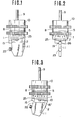
- Fig. 1 is a side view of a device in accordance with a preferred embodiment of the invention with a tool removed therefrom.
- Fig. 2 is a front view of the device in Fig. 1.
- Fig. 3 is a side view of the device, particularly illustrating that a rotary ring is rotated by 180 degrees and thereby a tool holding plate is inclined by 14 degrees.
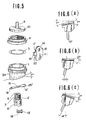
- Fig. 4 is a vertical sectional view of the device in Fig. 1, shown in an enlarged scale.
- Fig. 5 is a perspective view of essential components constituting the device, shown in the disassembled state.
- Fig. 6(a) is a side view of.the tool holding plate with a tool attached thereto, illustrating that it is not inclined.
- Fig. 6 (b), is a side view of the tool holding plate in Fig. 6(a), illustrating that it is inclined by 7 degrees.
- Fig. 6(c) is a side view of the tool holding plate in Fig. 6(a), illustrating that it is inclined by 14 degrees.
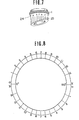
- Fig. 7 is a perspective view of the rotary ring of which lower end face is cut to 7 degrees, particularly illustrating how calibration lines are impressed on the peripheral surface of the rotary ring.
- Fig. 8 is a schematic view illustrating how calibration is made over the peripheral surface of the rotary ring,
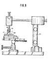
and - Fig. 9 is a side view of a surveyor with the device attached thereto, illustrating that the device is operated for a partial denture to be designed on a partially worked plaster model mounted on a table.
- Now, the present invention will be described in a greater detail hereunder with reference to the accompanying drawings which illustrate a preferred embodiment of the invention.
- As is best seen from Fig. 6, a device of the invention essentially comprises a rotary ring 1 of which lower end face is cut to a predetermined inclination angle, that is, 7 degrees in the illustrated embodiment, a
core 2 onto which said rotary ring 1 is rotatably fitted, atool holding plate 11 inserted into aslot 12 formed on the lower part of thecore 2 so as to turn about asupport shaft 13 which is fixedly fitted to saidtool holding plate 11, the latter having wing-shaped lateral projections of which upper face extending at the same inclination angle as that of the lower inclined end face of the rotary ring 1 and having a semi-cylindrical recess formed thereon, a transversely extendingshaft 16 inserted throughholes 17 at the upper part of thetool holding plate 11 along the semi-cylindrical recesses on the upper faces of the wing-shaped lateral projections, a ring-shaped washer 5 having a pair of inward projections located diametrically opposite to one another, said projections being fitted intogrooves 7 vertically extending across the male thread portion of thecore 2, alock ring 8 for inhibiting rotation of the rotary ring 1 at its lowermost end position end acover 10 threadably fitted onto the male thread portion of thecore 2. - To assure that the rotary ring 1 and the
lock ring 8 are easily rotated by an operator's hand they have a knurled portion respectively and the rotary ring 1 has a number ofcalibration lines 25 impressed along the wholeperipheral surface 24 thereof so as to indicate how atool 20 is inclined. In the illustrated embodiment a calibration line indicationg zero degree is located at the lefthand side of theperipheral surface 24 as seen in Fig. 1 and a calibration line indicating 14 degrees is located at the righthand side of the same. As is apparent from Fig. 8, an angular distance between the adjacent calibration lines is not equal along the wholeperipheral surface 24. It becomes largest between zero degree and one degree as well as 13 degrees and 14 degrees and it gradually decreases toward the middle part between zero degree and 14 degrees. - A
coil spring 3 is received in asmaller bore 6 on the male thread portion of thecore 2 so that its resilient force is transmitted to the rotary ring 1 via a key-shapedintermediate member 4 and awasher 5 so as to allow the rotary ring 1 to be normally thrusted toward the flat faces on both theend parts 19 and 19' of the transversely extendingshaft 16. To slidably receive the key-shaped intermediate member 4 aslot 7 is formed through the male thread portion of thecore 2 in the transverse direction at the lower end part of the vertically extendinggrooves 7. - As is apparent from Fig. 4, there is existent a very close clearance C between the
cover 10 and thelock ring 8 when the latter is turned to the lowermost position to inhibit . the rotary ring 1 form further rotation. As required, thelock ring 8 is turned in the opposite direction so as to be released from the locked state. - Since the laterally extending
shaft 16 extends through theholes 17 on thetool holding plate 11 and thehole 18 on thesupport shaft 13 along the semi-cylindrical recess on the upper end faces of the wing-shaped lateral projections, it is inclined at the same inclination angle as that of the lower inclined face of the rotary ring 1 and its axis intersects with the axis of thesupport shaft 13 at a right angle relative to one another which is fixedly fitted to thetool holding plate 11. - Both the
end parts 19 and 19' of the transversely extendingshaft 16 are cut to a flat face which is normally brought in slidable contact the lower inclined face of the rotary ring 1 while the latter is rotated. Thus, due to the slidable contact between the flat faces of theend parts 19 and 19' of the transversely extendingshaft 16 and the lower inclined face of the rotary ring 1 the transversely extendingshaft 16 is caused to rotate within a certain angular extent in the semi-cylindrical recesses on the upper faces of the wing-shaped lateral projections of thetool holding plate 11 as the rotary ring 1 is rotated. Provided that there is existent no transversely extending shaft on the upper faces of the wing-shaped lateral projection of thetool holding plate 11, it will result that the lower inclined end face of the rotary ring 1 comes in direct contact with the upper surfaces of the wing-shaped projections of thetool holding plate 11 whereby they wears quickly because of the fact that line contact is achieved therebetween during rotation of the rotary ring 1. To prevent occurance of line contact as described above there is provided the transversely extendingshaft 16 between the rotary ring 1 and thetool holding plate 11, said transversely extendingshaft 16 being caused to rotate within an appreciable extent of angle on the semi-cylindrical recesses on the upper faces of the wing-shaped projections of the tool holding plate.11. - In Fig. 4
reference numeral 22 designate a cutout formed at the lower part of the lefthand wing-shaped laterla projection 15 so that aset screw 23 firmly holding atool 20 on thetool holding plate 11 is accomodated in saidcutout 22. Thus, the device can be handled without any hindrance due to the existence of projection such as set screw or the like means. - Next, operation of the device will be described below.
- A
tool 20 is first inserted into a drilled hole 21 'on the tool holding plate and then it is firmly held thereon by tightening aset screw 23. The thus prepared device is attached to asurveyor 27 by inserting ashank 9 on thecover 10 into a collet of the surveyor 27 (see Fig. 9). - The device is displaced to the position located just in front of a plaster die to be inspected by actuating the parallel actuating mechanism of the
surveyor 27. - Prior to initiating measuring operation the
locking ring 8 is loosened so that the rotary ring 1 is easily rotated by an operator's hand. While this state is maintained, thetool 20 is brought in contact against the tapered surface of the plaster die. After it is confimed that thetool 20 assumes the position located in parallel to the tapered surface, the existing'inclination angle of the tapered surface of the wax pattern relative to a vertical plane can be measured by reading the numeral on the calibration line which is located in vertical alignment with thereference line 26 marked on the outermost end face of the transversely extendingshaft 16. - In this connection it should be noted that calibration is made for the device in such a manner that when the
tool 20 assumes the vertical posture without any inclination as illustrated in Fig. 4 and 6(a), the calibration line indicate . ing zero degree degree is located in vertical alignment with thereference line 26 as is best seen from Fig. 2, when the rotary ring 1 is rotated by 90 degrees and thetool 20 is inclined by 7 degrees as illustrated in Fig. 6 (b)., the calibration line indicating 7 degrees is located in vertical alignment with thereference line 26 and when the rotary ring 1 is rotated by 180 degrees as illustrated in Fig. 3 and thetool 20 is inclined by 14 degrees as illustrated 6(c), the calibration line indicating 14 degrees is located in vertical alignment with thereference line 26. - After the existing inclination angle of the tapered surface of the plaster die is measured, scraping operation is carried out. The
tool 20 is rearranged by manual operation such that it is inclined to a required inclination angle which is calculated in accordance with the Dr. Körber's "conus drown" therory and its cutting edge is oriented toward the tapered surface of the wax pattern. After completion of rearrangement thelock ring 8 is turned in the direction of locking. The whole device with thetool 20 inclined to the predetermined inclination angle is displaced toward the wax pattern by operating the parallel actuating mechanism of the surveyor and scraping operation is then carried out by manually handling the device. - As described above, any inclination of the
tool 20 in the range of 0 to 14 degrees can be obtained by rotating the rotary ring 1 at the largest by 180 degrees corresponding to rotation of the latter by a half turn. Accordingly, calibration is required only over the half of theperipheral surface 24 of the rotary ring 1 but in the illustrated embodiment of the invention the same calibration is made over the other half of theperipheral surface 24 of the rotary ring 1 as is apparent from Figs. 2 and 8 in order to assure that the existing inclination angle can be read from any direction. To identify the direction of observation it is convenient that the calibration lines on the one half of theperipheral surface 24 of the rotary ring 1 are colored with black and those on the other half of the same are colored with red. - The red colored reference line 26' on the righthand outermost end face of the transversely extending
shaft 16 as seen in the drawing is adapted to be located in vertical aligns ment with the red colored calibration lines on the other half of theperipheral surface 24 of the rotary ring 1 so that the existing inclination angle of the tool can be easily recognized from the opposite direction. - While the present has been described above merely with respect to a single preferred embodiment, it should of cource be understood that it should not be limited only to this but various changes or modifications may be made in a suitable manner without any departure from the spirit and scope of the invention.
Claims (9)
Applications Claiming Priority (2)
| Application Number | Priority Date | Filing Date | Title |
|---|---|---|---|
| JP57193526A JPS5982850A (en) | 1982-11-05 | 1982-11-05 | Taper measuring and cutting apparatus for fabricating artificial tooth support apparatus |
| JP193526/82 | 1982-11-05 |
Publications (2)
| Publication Number | Publication Date |
|---|---|
| EP0108366A1 true EP0108366A1 (en) | 1984-05-16 |
| EP0108366B1 EP0108366B1 (en) | 1987-03-04 |
Family
ID=16309534
Family Applications (1)
| Application Number | Title | Priority Date | Filing Date |
|---|---|---|---|
| EP83110846A Expired EP0108366B1 (en) | 1982-11-05 | 1983-10-29 | Device for measuring and scraping operations in the field of restorative dentistry |
Country Status (4)
| Country | Link |
|---|---|
| US (1) | US4493644A (en) |
| EP (1) | EP0108366B1 (en) |
| JP (1) | JPS5982850A (en) |
| DE (1) | DE3369905D1 (en) |
Cited By (1)
| Publication number | Priority date | Publication date | Assignee | Title |
|---|---|---|---|---|
| CN109596034A (en) * | 2018-12-18 | 2019-04-09 | 台州工交机械有限公司 | A kind of ball pin depth check tool |
Families Citing this family (4)
| Publication number | Priority date | Publication date | Assignee | Title |
|---|---|---|---|---|
| US4802846A (en) * | 1987-04-27 | 1989-02-07 | Posca Jorge E | Automatic surveyor for dental models |
| AR014089A1 (en) * | 2000-06-16 | 2001-02-07 | Ranalli Sebastian Luciano | DEVICE FOR PLANNING AND POSITIONING PLACEMENT OF A DENTARY IMPLANT, METHOD FOR PLANNING THE CORRECT PLACEMENT OF A DENTARY IMPLANT THAT SAVES SUCH DEVICE AND PRETOMOGRAPHIC GUIDE AND SURGICAL TEMPLATE OBTAINED BY MEANS OF THIS METHOD |
| CN104771238B (en) * | 2015-02-02 | 2016-08-24 | 西安交通大学口腔医院 | A kind of device measured for inclination of cusp |
| KR200484687Y1 (en) * | 2016-11-01 | 2017-11-16 | 고려대학교 산학협력단 | A tolerance measuring device for imitation dental prosthesis |
Citations (4)
| Publication number | Priority date | Publication date | Assignee | Title |
|---|---|---|---|---|
| CH249402A (en) * | 1943-11-11 | 1947-06-30 | Secowerk Wien Ges Fuer Praezis | Method and device for angle measurement. |
| US2544097A (en) * | 1946-08-05 | 1951-03-06 | John A Lentz | Parallelometer chuck |
| DE1766099A1 (en) * | 1968-04-03 | 1971-07-01 | Karlheinz Dr Koerber | Device for the production of conical crowns and their use |
| FR2446629A1 (en) * | 1979-01-17 | 1980-08-14 | Laudy Jean | Dental cast mounting for use with variety of tools - has swivel base fixed by screws and vertically adjustable column mounting pivoting tool support arm |
Family Cites Families (5)
| Publication number | Priority date | Publication date | Assignee | Title |
|---|---|---|---|---|
| US1910592A (en) * | 1932-08-22 | 1933-05-23 | John M Craigo | Dental instrument |
| US2007884A (en) * | 1933-09-25 | 1935-07-09 | Dental Res Corp | Dental carving machine |
| US2457090A (en) * | 1945-11-02 | 1948-12-21 | William Gold Refining Company | Attachment for dental surveying instruments |
| US2616176A (en) * | 1948-06-14 | 1952-11-04 | William F Rodin | Dental clasp surveyor and parallelometer |
| US2703453A (en) * | 1953-11-24 | 1955-03-08 | Landis Joseph | Dental model surveyor |
-
1982
- 1982-11-05 JP JP57193526A patent/JPS5982850A/en active Granted
-
1983
- 1983-10-29 EP EP83110846A patent/EP0108366B1/en not_active Expired
- 1983-10-29 DE DE8383110846T patent/DE3369905D1/en not_active Expired
- 1983-11-02 US US06/548,000 patent/US4493644A/en not_active Expired - Fee Related
Patent Citations (4)
| Publication number | Priority date | Publication date | Assignee | Title |
|---|---|---|---|---|
| CH249402A (en) * | 1943-11-11 | 1947-06-30 | Secowerk Wien Ges Fuer Praezis | Method and device for angle measurement. |
| US2544097A (en) * | 1946-08-05 | 1951-03-06 | John A Lentz | Parallelometer chuck |
| DE1766099A1 (en) * | 1968-04-03 | 1971-07-01 | Karlheinz Dr Koerber | Device for the production of conical crowns and their use |
| FR2446629A1 (en) * | 1979-01-17 | 1980-08-14 | Laudy Jean | Dental cast mounting for use with variety of tools - has swivel base fixed by screws and vertically adjustable column mounting pivoting tool support arm |
Cited By (2)
| Publication number | Priority date | Publication date | Assignee | Title |
|---|---|---|---|---|
| CN109596034A (en) * | 2018-12-18 | 2019-04-09 | 台州工交机械有限公司 | A kind of ball pin depth check tool |
| CN109596034B (en) * | 2018-12-18 | 2020-10-27 | 浙江工交机械股份有限公司 | Depth gauge for ball pin |
Also Published As
| Publication number | Publication date |
|---|---|
| JPH0344775B2 (en) | 1991-07-09 |
| EP0108366B1 (en) | 1987-03-04 |
| JPS5982850A (en) | 1984-05-14 |
| US4493644A (en) | 1985-01-15 |
| DE3369905D1 (en) | 1987-04-09 |
Similar Documents
| Publication | Publication Date | Title |
|---|---|---|
| US4048897A (en) | Laterally engagable and releasable nut assembly | |
| US3967377A (en) | Precision positioning device for tool blades and the like | |
| US5595080A (en) | Lock condition indicator device | |
| GB2030488A (en) | Adjustable boring tool | |
| JPH02240502A (en) | Effective diameter gauge | |
| US4493644A (en) | Device for measuring and scraping operations in the field of prestorative dentistry | |
| US2553004A (en) | Dividing protractor | |
| JPS5946501A (en) | Gage for inspecting depth of hole | |
| EP0327669B1 (en) | Dial bore gage | |
| US4015513A (en) | Indexing devices | |
| US4970799A (en) | Device for measuring a shaft keyway and method of using | |
| US1877307A (en) | Tolerance zone on gauges | |
| US3889382A (en) | Micrometer tooth measuring apparatus | |
| US4320581A (en) | Leveling | |
| US1921899A (en) | Micrometer caliper attachment | |
| US3135056A (en) | Gauges | |
| US2817258A (en) | Tool adjusting wrench | |
| US3150448A (en) | Dental surveyor attachment | |
| US5077907A (en) | Pipe measuring apparatus | |
| US3298141A (en) | Collet indexing and grinding fixture | |
| US3178828A (en) | Internal-and-external surface concentricity gauge | |
| US2192343A (en) | Cutter truing device | |
| US2203984A (en) | Indicating and measuring instrument | |
| US2527758A (en) | Die gauge | |
| US3486236A (en) | Inspection tool |
Legal Events
| Date | Code | Title | Description |
|---|---|---|---|
| PUAI | Public reference made under article 153(3) epc to a published international application that has entered the european phase |
Free format text: ORIGINAL CODE: 0009012 |
|
| AK | Designated contracting states |
Designated state(s): DE FR IT |
|
| 17P | Request for examination filed |
Effective date: 19841113 |
|
| GRAA | (expected) grant |
Free format text: ORIGINAL CODE: 0009210 |
|
| AK | Designated contracting states |
Kind code of ref document: B1 Designated state(s): DE FR IT |
|
| ITF | It: translation for a ep patent filed |
Owner name: ING. A. GIAMBROCONO & C. S.R.L. |
|
| REF | Corresponds to: |
Ref document number: 3369905 Country of ref document: DE Date of ref document: 19870409 |
|
| ET | Fr: translation filed | ||
| PLBE | No opposition filed within time limit |
Free format text: ORIGINAL CODE: 0009261 |
|
| STAA | Information on the status of an ep patent application or granted ep patent |
Free format text: STATUS: NO OPPOSITION FILED WITHIN TIME LIMIT |
|
| 26N | No opposition filed | ||
| ITTA | It: last paid annual fee | ||
| PGFP | Annual fee paid to national office [announced via postgrant information from national office to epo] |
Ref country code: FR Payment date: 19921028 Year of fee payment: 10 |
|
| PGFP | Annual fee paid to national office [announced via postgrant information from national office to epo] |
Ref country code: DE Payment date: 19921127 Year of fee payment: 10 |
|
| PG25 | Lapsed in a contracting state [announced via postgrant information from national office to epo] |
Ref country code: FR Effective date: 19940630 |
|
| PG25 | Lapsed in a contracting state [announced via postgrant information from national office to epo] |
Ref country code: DE Effective date: 19940701 |
|
| REG | Reference to a national code |
Ref country code: FR Ref legal event code: ST |