EP0108142B1 - Gasfühler und verfahren zu dessen verwendung - Google Patents
Gasfühler und verfahren zu dessen verwendung Download PDFInfo
- Publication number
- EP0108142B1 EP0108142B1 EP83902027A EP83902027A EP0108142B1 EP 0108142 B1 EP0108142 B1 EP 0108142B1 EP 83902027 A EP83902027 A EP 83902027A EP 83902027 A EP83902027 A EP 83902027A EP 0108142 B1 EP0108142 B1 EP 0108142B1
- Authority
- EP
- European Patent Office
- Prior art keywords
- electrode
- gas
- potential
- electrolyte
- sensor
- Prior art date
- Legal status (The legal status is an assumption and is not a legal conclusion. Google has not performed a legal analysis and makes no representation as to the accuracy of the status listed.)
- Expired
Links
- 238000000034 method Methods 0.000 title claims description 34
- 239000007789 gas Substances 0.000 claims abstract description 73
- BASFCYQUMIYNBI-UHFFFAOYSA-N platinum Chemical compound [Pt] BASFCYQUMIYNBI-UHFFFAOYSA-N 0.000 claims abstract description 36
- 229910052760 oxygen Inorganic materials 0.000 claims abstract description 27
- 239000001301 oxygen Substances 0.000 claims abstract description 27
- QVGXLLKOCUKJST-UHFFFAOYSA-N atomic oxygen Chemical compound [O] QVGXLLKOCUKJST-UHFFFAOYSA-N 0.000 claims abstract description 26
- 238000001179 sorption measurement Methods 0.000 claims abstract description 26
- 239000007788 liquid Substances 0.000 claims abstract description 14
- 229910052751 metal Inorganic materials 0.000 claims abstract description 5
- 239000002184 metal Substances 0.000 claims abstract description 5
- CURLTUGMZLYLDI-UHFFFAOYSA-N Carbon dioxide Chemical compound O=C=O CURLTUGMZLYLDI-UHFFFAOYSA-N 0.000 claims description 41
- 229910002092 carbon dioxide Inorganic materials 0.000 claims description 37
- 239000003792 electrolyte Substances 0.000 claims description 31
- 239000012528 membrane Substances 0.000 claims description 31
- 239000001569 carbon dioxide Substances 0.000 claims description 19
- 239000012530 fluid Substances 0.000 claims description 19
- RWSOTUBLDIXVET-UHFFFAOYSA-N Dihydrogen sulfide Chemical compound S RWSOTUBLDIXVET-UHFFFAOYSA-N 0.000 claims description 16
- 238000004140 cleaning Methods 0.000 claims description 14
- 229910000037 hydrogen sulfide Inorganic materials 0.000 claims description 14
- 230000002209 hydrophobic effect Effects 0.000 claims description 12
- 239000011159 matrix material Substances 0.000 claims description 9
- UGFAIRIUMAVXCW-UHFFFAOYSA-N Carbon monoxide Chemical compound [O+]#[C-] UGFAIRIUMAVXCW-UHFFFAOYSA-N 0.000 claims description 7
- 229910002091 carbon monoxide Inorganic materials 0.000 claims description 7
- PCHJSUWPFVWCPO-UHFFFAOYSA-N gold Chemical compound [Au] PCHJSUWPFVWCPO-UHFFFAOYSA-N 0.000 claims description 3
- 229910052737 gold Inorganic materials 0.000 claims description 3
- 239000010931 gold Substances 0.000 claims description 3
- -1 polypropylene Polymers 0.000 claims description 3
- 239000004743 Polypropylene Substances 0.000 claims description 2
- 229920001155 polypropylene Polymers 0.000 claims description 2
- 229920001296 polysiloxane Polymers 0.000 claims description 2
- 238000009792 diffusion process Methods 0.000 claims 3
- 229920002313 fluoropolymer Polymers 0.000 claims 1
- 229920000642 polymer Polymers 0.000 claims 1
- 230000000717 retained effect Effects 0.000 claims 1
- 230000001131 transforming effect Effects 0.000 claims 1
- 238000007254 oxidation reaction Methods 0.000 abstract description 21
- 230000036961 partial effect Effects 0.000 abstract description 21
- 230000003647 oxidation Effects 0.000 abstract description 20
- 229910052697 platinum Inorganic materials 0.000 abstract description 17
- 239000002156 adsorbate Substances 0.000 abstract description 16
- 230000009467 reduction Effects 0.000 abstract description 10
- LFQSCWFLJHTTHZ-UHFFFAOYSA-N Ethanol Chemical compound CCO LFQSCWFLJHTTHZ-UHFFFAOYSA-N 0.000 abstract description 8
- 229930195733 hydrocarbon Natural products 0.000 abstract description 8
- 150000002430 hydrocarbons Chemical class 0.000 abstract description 8
- 230000004044 response Effects 0.000 abstract description 4
- 238000010276 construction Methods 0.000 abstract description 3
- 150000002739 metals Chemical class 0.000 abstract description 2
- 230000035945 sensitivity Effects 0.000 abstract description 2
- 238000005259 measurement Methods 0.000 description 28
- 230000015572 biosynthetic process Effects 0.000 description 10
- 230000002829 reductive effect Effects 0.000 description 9
- 239000000203 mixture Substances 0.000 description 7
- UFHFLCQGNIYNRP-UHFFFAOYSA-N Hydrogen Chemical compound [H][H] UFHFLCQGNIYNRP-UHFFFAOYSA-N 0.000 description 6
- 238000010586 diagram Methods 0.000 description 6
- 239000001257 hydrogen Substances 0.000 description 6
- 229910052739 hydrogen Inorganic materials 0.000 description 6
- 230000035699 permeability Effects 0.000 description 6
- KDLHZDBZIXYQEI-UHFFFAOYSA-N Palladium Chemical compound [Pd] KDLHZDBZIXYQEI-UHFFFAOYSA-N 0.000 description 4
- 238000013459 approach Methods 0.000 description 4
- 230000008859 change Effects 0.000 description 4
- 230000000694 effects Effects 0.000 description 4
- 238000002848 electrochemical method Methods 0.000 description 4
- 239000000463 material Substances 0.000 description 4
- 230000002441 reversible effect Effects 0.000 description 4
- 230000001351 cycling effect Effects 0.000 description 3
- 238000013461 design Methods 0.000 description 3
- 239000012535 impurity Substances 0.000 description 3
- QSHDDOUJBYECFT-UHFFFAOYSA-N mercury Chemical compound [Hg] QSHDDOUJBYECFT-UHFFFAOYSA-N 0.000 description 3
- 229910052753 mercury Inorganic materials 0.000 description 3
- VNWKTOKETHGBQD-UHFFFAOYSA-N methane Chemical compound C VNWKTOKETHGBQD-UHFFFAOYSA-N 0.000 description 3
- MWUXSHHQAYIFBG-UHFFFAOYSA-N nitrogen oxide Inorganic materials O=[N] MWUXSHHQAYIFBG-UHFFFAOYSA-N 0.000 description 3
- 239000000376 reactant Substances 0.000 description 3
- 229910002089 NOx Inorganic materials 0.000 description 2
- 239000012891 Ringer solution Substances 0.000 description 2
- QAOWNCQODCNURD-UHFFFAOYSA-N Sulfuric acid Chemical compound OS(O)(=O)=O QAOWNCQODCNURD-UHFFFAOYSA-N 0.000 description 2
- RAHZWNYVWXNFOC-UHFFFAOYSA-N Sulphur dioxide Chemical compound O=S=O RAHZWNYVWXNFOC-UHFFFAOYSA-N 0.000 description 2
- 239000002253 acid Substances 0.000 description 2
- 230000004913 activation Effects 0.000 description 2
- 238000006243 chemical reaction Methods 0.000 description 2
- 238000002474 experimental method Methods 0.000 description 2
- 230000010354 integration Effects 0.000 description 2
- 150000002500 ions Chemical class 0.000 description 2
- 229910052741 iridium Inorganic materials 0.000 description 2
- GKOZUEZYRPOHIO-UHFFFAOYSA-N iridium atom Chemical compound [Ir] GKOZUEZYRPOHIO-UHFFFAOYSA-N 0.000 description 2
- 230000000670 limiting effect Effects 0.000 description 2
- 230000001590 oxidative effect Effects 0.000 description 2
- MUMZUERVLWJKNR-UHFFFAOYSA-N oxoplatinum Chemical compound [Pt]=O MUMZUERVLWJKNR-UHFFFAOYSA-N 0.000 description 2
- 229910052763 palladium Inorganic materials 0.000 description 2
- 239000008363 phosphate buffer Substances 0.000 description 2
- 230000010287 polarization Effects 0.000 description 2
- 239000011347 resin Substances 0.000 description 2
- 229920005989 resin Polymers 0.000 description 2
- 229910052703 rhodium Inorganic materials 0.000 description 2
- 239000010948 rhodium Substances 0.000 description 2
- MHOVAHRLVXNVSD-UHFFFAOYSA-N rhodium atom Chemical compound [Rh] MHOVAHRLVXNVSD-UHFFFAOYSA-N 0.000 description 2
- 150000003839 salts Chemical class 0.000 description 2
- 238000000926 separation method Methods 0.000 description 2
- 239000007787 solid Substances 0.000 description 2
- 125000006850 spacer group Chemical group 0.000 description 2
- BVKZGUZCCUSVTD-UHFFFAOYSA-M Bicarbonate Chemical compound OC([O-])=O BVKZGUZCCUSVTD-UHFFFAOYSA-M 0.000 description 1
- 239000007832 Na2SO4 Substances 0.000 description 1
- KJTLSVCANCCWHF-UHFFFAOYSA-N Ruthenium Chemical compound [Ru] KJTLSVCANCCWHF-UHFFFAOYSA-N 0.000 description 1
- PMZURENOXWZQFD-UHFFFAOYSA-L Sodium Sulfate Chemical compound [Na+].[Na+].[O-]S([O-])(=O)=O PMZURENOXWZQFD-UHFFFAOYSA-L 0.000 description 1
- 239000004809 Teflon Substances 0.000 description 1
- 229920006362 Teflon® Polymers 0.000 description 1
- 230000003213 activating effect Effects 0.000 description 1
- 229910045601 alloy Inorganic materials 0.000 description 1
- 239000000956 alloy Substances 0.000 description 1
- 239000010953 base metal Substances 0.000 description 1
- 238000009530 blood pressure measurement Methods 0.000 description 1
- 238000011109 contamination Methods 0.000 description 1
- 238000007405 data analysis Methods 0.000 description 1
- 230000007423 decrease Effects 0.000 description 1
- 230000001419 dependent effect Effects 0.000 description 1
- 238000001514 detection method Methods 0.000 description 1
- HTXDPTMKBJXEOW-UHFFFAOYSA-N dioxoiridium Chemical compound O=[Ir]=O HTXDPTMKBJXEOW-UHFFFAOYSA-N 0.000 description 1
- 239000007772 electrode material Substances 0.000 description 1
- 239000000835 fiber Substances 0.000 description 1
- 239000011521 glass Substances 0.000 description 1
- 239000003365 glass fiber Substances 0.000 description 1
- 239000003112 inhibitor Substances 0.000 description 1
- 230000003993 interaction Effects 0.000 description 1
- 230000002452 interceptive effect Effects 0.000 description 1
- 229910000457 iridium oxide Inorganic materials 0.000 description 1
- 230000002427 irreversible effect Effects 0.000 description 1
- 238000012886 linear function Methods 0.000 description 1
- 229910052943 magnesium sulfate Inorganic materials 0.000 description 1
- 230000004048 modification Effects 0.000 description 1
- 238000012986 modification Methods 0.000 description 1
- 229910052762 osmium Inorganic materials 0.000 description 1
- SYQBFIAQOQZEGI-UHFFFAOYSA-N osmium atom Chemical compound [Os] SYQBFIAQOQZEGI-UHFFFAOYSA-N 0.000 description 1
- 150000002926 oxygen Chemical class 0.000 description 1
- 239000004033 plastic Substances 0.000 description 1
- 229910003446 platinum oxide Inorganic materials 0.000 description 1
- 229920001343 polytetrafluoroethylene Polymers 0.000 description 1
- 239000004810 polytetrafluoroethylene Substances 0.000 description 1
- 239000011148 porous material Substances 0.000 description 1
- 229910000028 potassium bicarbonate Inorganic materials 0.000 description 1
- 235000015497 potassium bicarbonate Nutrition 0.000 description 1
- 239000011736 potassium bicarbonate Substances 0.000 description 1
- TYJJADVDDVDEDZ-UHFFFAOYSA-M potassium hydrogencarbonate Chemical compound [K+].OC([O-])=O TYJJADVDDVDEDZ-UHFFFAOYSA-M 0.000 description 1
- 238000004313 potentiometry Methods 0.000 description 1
- 239000010970 precious metal Substances 0.000 description 1
- 230000008569 process Effects 0.000 description 1
- 230000000754 repressing effect Effects 0.000 description 1
- 238000011160 research Methods 0.000 description 1
- 230000027756 respiratory electron transport chain Effects 0.000 description 1
- 229910052707 ruthenium Inorganic materials 0.000 description 1
- 239000002356 single layer Substances 0.000 description 1
- 229910000030 sodium bicarbonate Inorganic materials 0.000 description 1
- AJPJDKMHJJGVTQ-UHFFFAOYSA-M sodium dihydrogen phosphate Chemical compound [Na+].OP(O)([O-])=O AJPJDKMHJJGVTQ-UHFFFAOYSA-M 0.000 description 1
- 229910000162 sodium phosphate Inorganic materials 0.000 description 1
- 229910052938 sodium sulfate Inorganic materials 0.000 description 1
- 239000000243 solution Substances 0.000 description 1
- 238000003950 stripping voltammetry Methods 0.000 description 1
- 239000000126 substance Substances 0.000 description 1
- 239000003115 supporting electrolyte Substances 0.000 description 1
- 230000003746 surface roughness Effects 0.000 description 1
- 238000012360 testing method Methods 0.000 description 1
- 229910021654 trace metal Inorganic materials 0.000 description 1
Images




Classifications
-
- G—PHYSICS
- G01—MEASURING; TESTING
- G01N—INVESTIGATING OR ANALYSING MATERIALS BY DETERMINING THEIR CHEMICAL OR PHYSICAL PROPERTIES
- G01N27/00—Investigating or analysing materials by the use of electric, electrochemical, or magnetic means
- G01N27/26—Investigating or analysing materials by the use of electric, electrochemical, or magnetic means by investigating electrochemical variables; by using electrolysis or electrophoresis
- G01N27/416—Systems
- G01N27/49—Systems involving the determination of the current at a single specific value, or small range of values, of applied voltage for producing selective measurement of one or more particular ionic species
Definitions
- the invention is directed to sensors for determining the concentration of various gases (including C0 2 , CO, H 2 S, hydrocarbons, alcohol vapors, NO x , etc.) in gases and liquids electrochemically. More specifically, the invention is directed to a sensor for determining the partial pressure of gases by measuring the adsorbed species formed either electrochemically by reductive adsorption (such as in the case of C0 2 ) or oxidative adsorption (such as in the case of alcohol) or non-electrochemically by specific adsorption (such as in the case of CO and hydrocarbons) on the surface of platinum and other metals; and, optionally, substantially concurrently, but independently, oxygen content in gases or liquids.
- gases including C0 2 , CO, H 2 S, hydrocarbons, alcohol vapors, NO x , etc.
- Presently employed electrochemical gas sensors are either of the potentiometric or the polarographic type (including other current measuring approaches).
- Potentiometric sensors are basically modified pH-electrodes whose operating principle is based on the measurement of a potential that is effectively a linear function of the logarithm of H + ion concentration.
- electrochemical sensors for carbon dioxide, hydrogen sulfide, nitrogen oxides, sulfur dioxide, etc. belong to this category.
- P C02 partial pressure of carbon dioxide
- Polarographic type sensors and other sensors based on a current measurement have a two- electrode or a three-electrode configuration.
- the working principle of this type of sensor is based on the measurement of a current, usually the limiting current, of an oxidation (or reduction) reaction involving the gas to be measured.
- the magnitude of this current is made proportional to the partial pressure of the gas in the environment.
- electrochemical sensors for oxygen, carbon monoxide, and alcohol belong to this type.
- the major problems of this type of sensor are low sensitivity and poor selectivity.
- a primary objective of this invention is to provide an electrochemical method of measuring the partial pressure of various gases (such as CO, C0 2 , H 2 S, NO x , alcohol vapors, hydrocarbons, etc.) by electrochemically measuring the amount of chemisorbed species formed on a metal electrode under controlled conditions.
- gases such as CO, C0 2 , H 2 S, NO x , alcohol vapors, hydrocarbons, etc.
- a further objective of this invention is to provide an electrochemical method of determining the partial pressure of a number of gases, such as the ones mentioned above, and oxygen content substantially concurrently and independently with a single sensor.
- a still further objective of the invention is to provide a sensor for determining the partial pressure of certain gases in gas mixtures and liquids by measuring the amount of adsorbed species formed either electrochemically (via reductive or oxidation processes) or non-electrochemically (i.e., chemisorption) on an electrode surface.
- a still further objective of the invention is to provide a sensor for determining the partial pressure of various gases as mentioned above and oxygen content substantially concurrently and independently in gases and liquids with a single sensor.
- the realization of the objectives of this invention is based on the concept of measuring the amount of adsorbed electroactive species formed on a platinum or other electrode surface under conditions whereby this amount (coverage) is a function of partial pressure of the gas to be determined only.
- the electrodes are separated from the environment, preferably by a hydrophobic membrane which is impermeable to electrolyte, but permeable to gas.
- an electrolyte Positioned behind this membrane on the electrode side is an electrolyte which is compatible with the gaseous species to be measured (in the case of CO 2 , as an example, this electrolyte can be acid, phosphate buffer, bicarbonate solution with an inert salt, etc.).
- the sensor contains, in addition to the working electrode on which the absorbed electroactive species is formed and the counter electrode, a reference electrode or an electrolytic bridge to an external reference electrode. In some situations, the counter electrode can also be used as the reference electrode.
- the working electrode is platinum or other precious metal such as palladium, iridium, rhodium, osmium, ruthenium, gold, and alloys thereof or alloyed with base metals, which may have a smooth or a high surface area.
- the measurement is based on the potential control approach which involves the consecutive application to the working electrode, over a short period of time, of at least two potential pulses, using a potentiostat, as follows:
- the amount (coverage) of the adsorbed species is a function of the electrode potential, electrode roughness factor, gas concentration in the immediate neighborhood of the electrode, and time.
- the gas concentration in the immediate surrounding of the electrode is related to the partial pressure of the gas in the external environment and depends on the mass transport characteristics of the membrane and electrolyte.
- the amount of adsorbate formed before saturation will depend on the membrane permeability and the partial pressure of the gas to be determined if all other factors are kept constant.
- the gas partial pressure can be determined by using kinetic rates of adsorbate formation or by using the isotherm between adsorbate coverage and gas-concentration.
- the measuring potential pulse can be obtained poten- tiodynamically, i.e., by controlling the potential-time function between the working (sensing) and reference electrode, or galvanostatically, i.e., by controlling the current between the working and counter electrodes.
- the charge passed during the measuring step can be determined by electronically integrating the current and converting to partial pressure units.
- Oxygen interaction can be kept very low because during the adsorbate-forming pulse the current for adsorbate formation is integrated, and the current due to oxygen reduction is not included.
- This electrochemical gas sensing method is highly sensitive because it integrates the current required to oxidize an adsorbed species on the electrode akin to the approach of stripping vol- tammetry which is commonly used in the measurement of trace metal in liquids.
- This electrochemical gas sensing method is also inherently far more selective in the presence of co-reactants as compared to standard polarographic or potentiometric method because it offers a variety of choices in operating parameters and output data analysis techniques.
- the selectivity of the gas sensor can be significantly enhanced by:
- the adsorption potential pulse becomes an important parameter in terms of selectivity of the sensor. For example, CO is adsorbed on platinum in potential regions of 0.0 to 0.75 V versus RHE, whereas C0 2 is reductively adsorbed in 0.0 to 0.4 V regions. Therefore, it is possible to choose a higher adsorption potential (in the region of 0.40 to 0.75 V) to eliminate the interference of C0 2 in the gas mixture.
- the oxidation current peaks may be well separated during the constant sweep rate anodic ramp to allow the integration of individual peaks (or the current peak of interest) in a defined potential range.
- the oxidation current peaks of "Reduced-C02" and CO are approximately 100 mV apart.
- separation of oxidation current peaks may be accomplished by varying the slope of the anodic ramp since for irreversible oxidation of an adsorbed species, the peak potential is a function of the electron transfer rate.
- the anodic ramp may be "broken" into several segments having different ramp rates. Fine tuning the ramp rates and judicious choice of the portion(s) of the output current curve for microprocessor integration can result in high selectivity.
- a limiting current (polarographic) method can be used to determine its concentration using the same sensor.
- hydrocarbons e.g., CH 4
- adsorb strongly at higher temperatures whereas at room temperature the coverage is rather negligible.
- the same sensor can be made more selective to methane by operating it at a higher temperature (e.g., 60°C. or above).
- a sensor 10 to measure carbon dioxide in liquids includes a plastic cylinder 22; a rectangularly shaped platinum working electrode 12, approximately 1.25 mm x 6 mm, which is sandwiched between two interconnected platinum counter electrodes 14 of similar shape and size positioned in parallel relation.
- the surfaces of the electrodes were ground flush with 240, 320, 400, and 600 grit SiC paper. The flush surfaces were then platinized to render a surface roughness factor of approximately 100.
- the smooth basal surface of the resin has an opening 18 for a capillary 20 running parallel to the cylinder axis.
- This capillary filled with hydrophilic fibers 24 to avoid convection, is used as an ionic bridge for the reference electrode.
- a 125 p thick non-woven glass fiber spacer matrix 26 pre- wetted with electrolyte (internal electrolyte) is placed over the surfaces of the electrodes and a 25 p thick Teflon membrane 28 having a 0.2 ⁇ pore size is mounted over the wetted spacer to separate the internal electrolyte from the external environment.
- Premixed and preanalyzed C0 2 /N 2 mixtures were used which covered a wide P C02 range from 0 to 760 mm mercury.
- the gas was first passed through a presaturator maintained at 37°C. before entering the cell.
- the cell was allowed to equilibrate for at least 20 minutes before any measurements were made for a new gas composition.
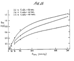
- the working electrode Prior to the measurements, the working electrode was cleaned by cycling it from 0 to 1500 mV (vs. RHE) using a triangular wave form similar to that shown in FIGURE 8 at a sweep rate of 500 mV/sec. The potential of the working electrode was then brought to E ads (70 mV vs. RHE) for a period of t ads (which in three sets of measurements was, respectively, 40, 60, and 120 seconds) to allow reductive adsorption of carbon dioxide to take place. This was immediately followed by an applied anodic potential ramp (AR) at a sweep rate of 50 mV/sec to oxidize the adsorbed "Reduced-C0 2 " species. The oxidation current was recorded as a function of potential shown in FIGURE 14.
- E ads 70 mV vs. RHE
- t ads which in three sets of measurements was, respectively, 40, 60, and 120 seconds
- the current peak located in the 500 to 800 mV (vs. RHE) potential region is due to the "Reduced-C0 2 " oxidation.
- This current was integrated into charge (Q ox ) (with subtraction of the background charge, i.e., charge with no CO 2 present) which was used as a measure of chemisorbed "Reduced-C02" to quantitatively determine Pco 2 .
- the current peak could also be used as an indication of Q ox and, thus, Pco 2 .
- a Princeton Applied Research 173 potentiostat, a Hewlett Packard 3310B function generator, and a Hewlett Packard 7047A X-Y recorder were used in the measurement.
- the integrated charge Q ox is shown as a function of Pco 2 for the three sets of measurements.
- FIGURE 15 shows that in the range from 0 to 152 mm Hg the charge varies in substantially linear manner with Pco 2 .
- the working electrode Prior to the measurements, the working electrode was cleaned by cycling it from 0 to 1500 mV (vs. RHE) using a triangular wave form similar to that shown in FIGURE 8 at a sweep rate of 500 mV/sec. The potential of the working electrode was then brought to E ads (70 mV vs. RHE) for a period of t ads (which was 5 seconds for the actual measurements) to allow the chemisorption of CO to take place. This was immediately followed by an applied anodic potential ramp (AR) at 50 mV/sec to oxidize the chemisorbed CO on the electrode. The oxidation current was recorded as a function of potential as shown in FIGURE 16.
- E ads 70 mV vs. RHE
- t ads which was 5 seconds for the actual measurements
- the current peak in the potential range of 700 to 900 mV is due to chemisorbed CO oxidation to C0 2 .
- This current is integrated into charge (Q ox ) (subtracting the background charge with no CO present) which is used as a measure of P co .
- the integrated charge Q ox is shown as a function of P co .
- the charge (Q ox ) varies in substantially linear relation with P co .
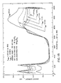
- the detection of hydrogen sulphide has been determined in a liquid containing dissolved hydrogen sulphide under the following conditions: 1 M H 2 SO 4 is employed as the internal electrolyte as well as the external fluid containing hydrogen sulphide.
- the electrochemical measurement was carried out at room temperature. Premixed and preanalyzed H 2 S/N 2 mixture at a H 2 S concentration of 850 ppm was used. The same precautionary measures and experimental techniques as the ones adopted in the previous examples for carbon dioxide and carbon monoxide were used.
- the platinum working electrode was cleaned by cycling from 0 to 1500 mV (vs. RHE) using a triangular wave form at a sweep rate of 500 mV/sec.
- the potential of the working electrode was then brought to E ads for a period of time t ads to allow the adsorption of H 2 S to take place.
- E ads ranged from 70 to 370 mV (vs. RHE) and t ads from 1 to 20 minutes.
- AR anodic potential ramp
- the oxidation current peak was found to be 1200 mV (vs. RHE) as shown in FIGURE 18.
- the current peak which serves as an indicator of the amount of H 2 S adsorbed on the working electrode, became larger with increasing t ads .
- the hydrogen adsorption charge in the potential range of from 0 to 300 mV decreases as the amount of chemisorbed H 2 S species increases. This provides another method of measuring chemisorbed gases.
- the sensor can be modified as shown in FIGURE 3.
- the sensor cell includes a housing 36, working electrode 12, and counter electrode 14.
- the internal electrolyte is contained in reservoir 38.
- Counter electrode 14 and reference electrode 40 are remotely positioned from the working electrode in the electrolyte reservoir. This sensor configuration allows gas concentration measurements in gases as well as in liquids.
- the reference electrode can be positioned within the cylindrical housing in accordance with the embodiment of FIGURE 1, and spaced from the counter and working electrodes within an extension of capillary 20.
- the reference electrode can be contained within cylinder 22 and positioned substantially flush with the basal surface of the resin.
- the capillary 20, as such, is not essential.
- the working electrode, counter electrode, and reference electrode are in contact with an electrolyte impregnated within a matrix.
- FIGURE 6 is a block diagram of an electrochemical measuring system utilizing potential control.
- the reference electrode, working electrode, and counter electrode are all connected to a potentiostat which, in turn, is connected to an integrator and a wave form generator.
- the sensor construction and electrical parameters of the sensor are interrelated. It is possible to predict qualitatively how changing one parameter (e.g., electrode roughness) is going to affect another parameter, e.g., time at adsorption potential, potential sweep rate for adsorbed species measurement, etc. These interrelated qualitative characteristics are used to select values for parameters when changing another parameter.
- one parameter e.g., electrode roughness
- another parameter e.g., time at adsorption potential, potential sweep rate for adsorbed species measurement, etc.
- a number of signal shapes can be input to the potentiostat to form the adsorbed species to quantitatively oxidize the adsorbate formed, and to periodically clean the platinum surface from contamination by adventitious impurities.
- a trapezoidal wave shape as illustrated in FIGURE 7 can be used.
- the adsorbed species is formed during the time (t ads ) at the adsorption potential (E ads ) (t ads and E ads are kept fixed).
- the adsorbate is oxidized during the anodic potential ramp (AR); and during a fraction of this ramp, the current is integrated to determine the amount of formed adsorbate, or the current at a designant potential within the oxidation peak, or the magnitude of the peak.
- accumulated impurities are removed from the surface of the electrode and substituted by chemisorbed oxygen which is reduced during the cathodic ramp (CR).
- the initial selection of time of adsorption can be readily made since the saturation of the electrode with an adsorbed species is usually known (for "Reduced-C02" it corresponds to a charge of about 0.2 mCoul/cm 2 of electrode real surface area), and will vary with the roughness factor of the electrode studied.
- Another variable in the sensor is the permeability of the membrane. In a "membrane limited" sensor, the amount of adsorbate formed for a given time period before saturation will depend on the permeability of the membrane.
- the slope of the ramp AR is selected so as to (i) oxidize all adsorbed species in a reasonable time; (ii) minimize activation polarization so as to avoid oxidation of the adsorbate at too high potentials, at which Pt-O formation occurs, and (iii) minimize ohmic polarization between sensing and counter electrodes.
- the value of the AR slope will depend on the roughness factor and typically will vary from 1 volt/sec to 10 mV/sec, which ranges from 1 second to about 1.5 minutes for a 1 volt ramp.
- the cleaning potential (E cl ) is between 1 volt and 1.5 volt.
- the duration t el at E cl will be selected to substantially form a monolayer of chemisorbed oxygen.
- FIGURE 9 illustrates a further modified wave shape with anodic and cathodic potential ramps, with a potential step in the cathodic ramp for reducing the Pt-O film and to determine substantially concurrently the oxygen concentration of the fluid being measured.
- FIGURE 10 illustrates a modified wave shape with constant potential pulses which can be employed and includes also provision for reducing the Pt-0 to platinum and to determine substantially concurrently the oxygen concentration of the fluid being measured.
- potentiostats can be internally wired to be switched from the potentiostatic to the galvanostatic mode.
- the resulting electrode potential-time curve shows a well- defined step or plateau (step A in FIGURE 11a), the duration of which is proportional to the amount of adsorbed species for a fixed current.
- the potential rises to oxidize the electrode surface (step B of FIGURE 11a) (equivalent to a cleaning pulse).
- the operating mode is changed to the potential controlled mode, starting again the adsorption pulse.
- This method can be modified to substantially concurrently measure oxygen as shown in FIGURE 11b.
- the adsorbate is formed at a constant potential; this is followed by measuring the adsorbed species and oxidizing the platinum surface at a constant current, then the operating mode is changed to a controlled potential mode by impressing a controlled potential pulse at which the oxygen reduction current is measured after a certain duration of this pulse. The cycle is then repeated.
- a number of gases can also be measured using a purely galvanostatic approach as shown in the block diagram in FIGURE 12.
- a galvanostat is connected to each of the working and counter electrodes through a switch to reverse the current flow.
- the working electrode and a reference electrode are connected to an E-t recorder, integrator, or timer.
- an electroactive species is adsorbed (either electrochemically by partial reduction or oxidation, or non-electrochemically by chemisorption); and on current reversal the adsorbed species is oxidized as above.
- the current is reversed again to provide a reduction of the platinum oxygen surface.
- the oxygen can be measured by measuring the length of the step or plateau. This step is followed by the adsorbate formation step as illustrated in FIGURES 12a and 12b.
- Still another method of measuring gases involves the combination of an adsorption step (potentiostatic or galvanostatic) with an open circuit potential measurement.
- cleaning occurs at a constant potential or constant anodic current; this is followed by reversal of current or application of a potential pulse so that the platinum oxide is reduced; this is followed by the formation of the adsorbed electroactive species as the potential falls at a constant current or a step down potential pulse is applied.
- the amount of the adsorbed species is determined by measuring the open circuit potential (as illustrated in FIGURE 13), which is related to this amount.
- the sensor as above discussed can be used to determine oxygen content in a fluid by measuring the oxygen reduction current at appropriate potentials.
- This oxygen measurement does not interfere with the gas partial pressure measurement because the oxygen determination is a current- measurement, which can be done at potentials at which no co-reacting gases is electroactive, and the gas concentration measurement is a charge-measurement; and even if oxygen is reduced at the potentials of adsorbate formation and re-oxidation, the effect of the current due to oxygen reduction is low compared with the magnitude of the integrated current due to the formation of adsorbed species (and subsequent oxidation of the chemisorbed species).
- Pg as and P 02 will depend on electrode roughness factors and on membrane permeability.
- Oxygen measurement can be enhanced by modifying the wave shape.
- the CR can be modified by introducing a waiting time at a fixed potential (above the range of potentials of carbon dioxide reduction) at which oxygen is measured.
- the sensors provided according to the present invention and the method of measuring a number of gases (e.g., CO, CO 2 , H 2 S, alcohol . vapors, hydrocarbons, etc.) based on the determination of the coverage of an intermediate electroactive adsorbed species formed on the electrode are highly sensitive.
- gases e.g., CO, CO 2 , H 2 S, alcohol . vapors, hydrocarbons, etc.
- the sensors in addition to their being capable of miniaturization, have electrodes having little or no drift as is encountered in ion selective and solid state electrodes. Accordingly, the electrodes have unique capabilities where accuracy in determination is essential.
- the internal calibration of the sensor to take into consideration background and surface area changes can be accomplished instrumentally by dividing Q ox by a charge or current, determined from i-E curves, which is independent of the gas concentration and dependent on electrode surface areas.
Landscapes
- Chemical & Material Sciences (AREA)
- Life Sciences & Earth Sciences (AREA)
- Health & Medical Sciences (AREA)
- Physics & Mathematics (AREA)
- Chemical Kinetics & Catalysis (AREA)
- Electrochemistry (AREA)
- Molecular Biology (AREA)
- Analytical Chemistry (AREA)
- Biochemistry (AREA)
- General Health & Medical Sciences (AREA)
- General Physics & Mathematics (AREA)
- Immunology (AREA)
- Pathology (AREA)
- Investigating Or Analyzing Materials By The Use Of Electric Means (AREA)
Claims (34)
Priority Applications (1)
| Application Number | Priority Date | Filing Date | Title |
|---|---|---|---|
| AT83902027T ATE33311T1 (de) | 1982-05-11 | 1983-05-10 | Gasfuehler und verfahren zu dessen verwendung. |
Applications Claiming Priority (4)
| Application Number | Priority Date | Filing Date | Title |
|---|---|---|---|
| US37714382A | 1982-05-11 | 1982-05-11 | |
| US377143 | 1982-05-11 | ||
| US06/430,688 US4508598A (en) | 1982-05-11 | 1982-09-30 | Gas sensor and method of using same |
| US430688 | 1999-10-29 |
Publications (3)
| Publication Number | Publication Date |
|---|---|
| EP0108142A1 EP0108142A1 (de) | 1984-05-16 |
| EP0108142A4 EP0108142A4 (de) | 1984-09-19 |
| EP0108142B1 true EP0108142B1 (de) | 1988-03-30 |
Family
ID=27007689
Family Applications (1)
| Application Number | Title | Priority Date | Filing Date |
|---|---|---|---|
| EP83902027A Expired EP0108142B1 (de) | 1982-05-11 | 1983-05-10 | Gasfühler und verfahren zu dessen verwendung |
Country Status (4)
| Country | Link |
|---|---|
| US (1) | US4508598A (de) |
| EP (1) | EP0108142B1 (de) |
| DE (1) | DE3376145D1 (de) |
| WO (1) | WO1983004095A1 (de) |
Families Citing this family (16)
| Publication number | Priority date | Publication date | Assignee | Title |
|---|---|---|---|---|
| ATE37446T1 (de) * | 1984-02-20 | 1988-10-15 | Yokogawa Electrofact Bv | Elektrodenanordnung fuer die messung der konzentration eines elektrochemisch aktiven stoffes. |
| GB8512796D0 (en) * | 1985-05-21 | 1985-06-26 | Bellhouse Brian John | Testing liquids |
| US4805624A (en) * | 1985-09-09 | 1989-02-21 | The Montefiore Hospital Association Of Western Pa | Low-potential electrochemical redox sensors |
| US4834101A (en) * | 1987-06-26 | 1989-05-30 | The University Of Michigan | Catheter-type electrochemical sensors |
| US5064516A (en) * | 1987-07-16 | 1991-11-12 | Gas Research Institute | Measuring gas levels |
| US5007988A (en) * | 1987-09-08 | 1991-04-16 | Westinghouse Electric Corp. | Method for determining the concentration of a plurality of combustible gases in a stream |
| DE4030873C2 (de) * | 1990-09-29 | 2000-05-04 | Conducta Endress & Hauser | Verfahren zur Konzentrationsbestimmung von elektrochemisch umsetzbaren Gasen |
| WO1994028372A1 (en) * | 1993-05-25 | 1994-12-08 | Rosemount Inc. | Organic chemical sensor |
| US5683443A (en) * | 1995-02-07 | 1997-11-04 | Intermedics, Inc. | Implantable stimulation electrodes with non-native metal oxide coating mixtures |
| US5654030A (en) * | 1995-02-07 | 1997-08-05 | Intermedics, Inc. | Method of making implantable stimulation electrodes |
| CA2235021C (en) * | 1998-04-14 | 2007-06-26 | Jean-Pierre Gibeault | A method and apparatus for monitoring gas(es) in a dielectric fluid |
| US6138499A (en) * | 1998-08-27 | 2000-10-31 | Sun Electric Europe B.V. | Exhaust emission analysis system incorporating pulse dampening |
| US7109853B1 (en) | 1999-04-26 | 2006-09-19 | Cherry Corporation | System for detecting and releasing a person locked in the trunk of a vehicle |
| DE10047708C2 (de) | 2000-09-25 | 2003-09-18 | Kempe Gmbh | Sensor zur Messung von O¶2¶ Konzentrationen in Flüssigkeiten |
| US7909981B2 (en) * | 2004-03-03 | 2011-03-22 | Perkinelmer Health Sciences, Inc. | Method and apparatus for improving the performance of an electrochemical sensor |
| US7664607B2 (en) | 2005-10-04 | 2010-02-16 | Teledyne Technologies Incorporated | Pre-calibrated gas sensor |
Family Cites Families (4)
| Publication number | Priority date | Publication date | Assignee | Title |
|---|---|---|---|---|
| US3539455A (en) * | 1965-10-08 | 1970-11-10 | Leland C Clark Jr | Membrane polarographic electrode system and method with electrochemical compensation |
| DE2618392A1 (de) * | 1975-04-28 | 1976-11-11 | Mitsubishi Chem Ind | Voltammetrieanordnung |
| US4166775A (en) * | 1976-02-05 | 1979-09-04 | The United States Of America As Represented By The Secretary Of The Interior | Electrochemical gas monitoring method |
| GB2005418B (en) * | 1977-07-26 | 1982-04-21 | Searle & Co | Electrochemical sensor system |
-
1982
- 1982-09-30 US US06/430,688 patent/US4508598A/en not_active Expired - Lifetime
-
1983
- 1983-05-10 WO PCT/US1983/000712 patent/WO1983004095A1/en not_active Ceased
- 1983-05-10 EP EP83902027A patent/EP0108142B1/de not_active Expired
- 1983-05-10 DE DE8383902027T patent/DE3376145D1/de not_active Expired
Non-Patent Citations (5)
| Title |
|---|
| N, Electroanalytical Chemistry and Interfacial Electrochemistry, Recieved 29 November 1968, S.B. Brummer, Lathleen Cahill, Kinetics Of Reductive Adsorption of CO2 on Smooth Pt Electrodes, 21 (1969), pp. 463-482 * |
| N, Electrochimica Acta, Recieved 12 December 1966, M.W. Breiter, On The Nature of Reduced Carbon Dioxide, 12 (1967) pp. 1213-1218 * |
| N, Electrochimica Acta, Recieved 19 March 1963, J. Giner, Electrochemical Reduction of CO2 on Platin um Electrodes in Acid Solutions, 8 (1963) pp. 857-865 * |
| N, Journal of Electroanalytical Chemistry Recieved 23 June 1982, B. Beden, A. Bewick, M. Razaq, J. Weber, on the Nature of Reduced CO2 An IR Spectroscopic Investigation, 139 (1982) pp. 203-206 * |
| N, Journal of Electroanalytical Chemistry, Received 19 January 1968, M.W. Breiter Comparative Oxidation of Chemisorbed Carbon Monoxide Reduced Carbon Dioxide and Species Formed During The Methanol Oxidation, 19 (1968) pp. 1310136 * |
Also Published As
| Publication number | Publication date |
|---|---|
| EP0108142A1 (de) | 1984-05-16 |
| EP0108142A4 (de) | 1984-09-19 |
| US4508598A (en) | 1985-04-02 |
| WO1983004095A1 (en) | 1983-11-24 |
| DE3376145D1 (en) | 1988-05-05 |
Similar Documents
| Publication | Publication Date | Title |
|---|---|---|
| US4729824A (en) | Gas sensor and method of using same | |
| EP0108142B1 (de) | Gasfühler und verfahren zu dessen verwendung | |
| Pingarrón et al. | Terminology of electrochemical methods of analysis (IUPAC Recommendations 2019) | |
| JP2648337B2 (ja) | 酸性ガスセンサー | |
| US6224745B1 (en) | Process and device for continuously detecting at least one substance in a gaseous or liquid mixture by means of a sensor electrode | |
| EP2278321B1 (de) | Sensor zum Messen einer Zielkomponente in gasförmigen oder flüssigen Proben | |
| US3915831A (en) | Hydrogen sulfide sensing cell | |
| CA2011679A1 (en) | Device and method for detecting ionic components in solution | |
| US3897315A (en) | Method of determining hydrogen sulfide | |
| US5445726A (en) | Process and device for prolonging the usage time and reducing the temperature dependence of ion-selective polymer membrane electrodes | |
| US5076904A (en) | Electrochemical measuring cell for determining ammonia or hydrazine in a measuring sample | |
| US3909384A (en) | Electro-chemical sensors for trace gases | |
| US3859191A (en) | Hydrogen cyanide sensing cell | |
| US3878080A (en) | Carbon monoxide sensor | |
| CN108291890B (zh) | 脉冲电位气体传感器 | |
| Sharma et al. | Electrochemical sensors | |
| US5228974A (en) | Electrochemical measuring cell for determining ammonia or hydrazine in a measuring sample | |
| JP3067532B2 (ja) | 電気化学素子及び窒素酸化物濃度測定装置 | |
| US3830709A (en) | Method and cell for sensing nitrogen oxides | |
| Laitinen et al. | Potentiometric Determination of Oxygen Using the Dropping Mercury Electrode1 | |
| GB2073430A (en) | Gas detection device | |
| Trapp et al. | Development of a coulometric CO2 gas sensor | |
| Zhou et al. | Multi-sensor technique and solid-state electrochemical sensor system for real-time and dynamic monitoring of multi-component gases | |
| JPH0562298B2 (de) | ||
| Salaun et al. | Integrated microanalytical system coupling permeation liquid membrane and voltammetry for trace metal speciation. Technical description and optimization |
Legal Events
| Date | Code | Title | Description |
|---|---|---|---|
| PUAI | Public reference made under article 153(3) epc to a published international application that has entered the european phase |
Free format text: ORIGINAL CODE: 0009012 |
|
| 17P | Request for examination filed |
Effective date: 19840104 |
|
| AK | Designated contracting states |
Designated state(s): AT BE CH DE FR GB LI NL SE |
|
| GRAA | (expected) grant |
Free format text: ORIGINAL CODE: 0009210 |
|
| AK | Designated contracting states |
Kind code of ref document: B1 Designated state(s): AT BE CH DE FR GB LI NL SE |
|
| PG25 | Lapsed in a contracting state [announced via postgrant information from national office to epo] |
Ref country code: NL Effective date: 19880330 Ref country code: BE Effective date: 19880330 Ref country code: AT Effective date: 19880330 |
|
| REF | Corresponds to: |
Ref document number: 33311 Country of ref document: AT Date of ref document: 19880415 Kind code of ref document: T |
|
| PG25 | Lapsed in a contracting state [announced via postgrant information from national office to epo] |
Ref country code: SE Effective date: 19880331 |
|
| REF | Corresponds to: |
Ref document number: 3376145 Country of ref document: DE Date of ref document: 19880505 |
|
| ET | Fr: translation filed | ||
| NLV1 | Nl: lapsed or annulled due to failure to fulfill the requirements of art. 29p and 29m of the patents act | ||
| PLBE | No opposition filed within time limit |
Free format text: ORIGINAL CODE: 0009261 |
|
| STAA | Information on the status of an ep patent application or granted ep patent |
Free format text: STATUS: NO OPPOSITION FILED WITHIN TIME LIMIT |
|
| 26N | No opposition filed | ||
| PGFP | Annual fee paid to national office [announced via postgrant information from national office to epo] |
Ref country code: GB Payment date: 19920505 Year of fee payment: 10 |
|
| PGFP | Annual fee paid to national office [announced via postgrant information from national office to epo] |
Ref country code: DE Payment date: 19920518 Year of fee payment: 10 |
|
| PGFP | Annual fee paid to national office [announced via postgrant information from national office to epo] |
Ref country code: FR Payment date: 19920522 Year of fee payment: 10 |
|
| PGFP | Annual fee paid to national office [announced via postgrant information from national office to epo] |
Ref country code: CH Payment date: 19920820 Year of fee payment: 10 |
|
| PG25 | Lapsed in a contracting state [announced via postgrant information from national office to epo] |
Ref country code: GB Effective date: 19930510 |
|
| PG25 | Lapsed in a contracting state [announced via postgrant information from national office to epo] |
Ref country code: LI Effective date: 19930531 Ref country code: CH Effective date: 19930531 |
|
| GBPC | Gb: european patent ceased through non-payment of renewal fee |
Effective date: 19930510 |
|
| PG25 | Lapsed in a contracting state [announced via postgrant information from national office to epo] |
Ref country code: FR Effective date: 19940131 |
|
| REG | Reference to a national code |
Ref country code: CH Ref legal event code: PL |
|
| PG25 | Lapsed in a contracting state [announced via postgrant information from national office to epo] |
Ref country code: DE Effective date: 19940201 |
|
| REG | Reference to a national code |
Ref country code: FR Ref legal event code: ST |