EP0108025A1 - Spacer plate for a membrane apparatus - Google Patents
Spacer plate for a membrane apparatus Download PDFInfo
- Publication number
- EP0108025A1 EP0108025A1 EP83420165A EP83420165A EP0108025A1 EP 0108025 A1 EP0108025 A1 EP 0108025A1 EP 83420165 A EP83420165 A EP 83420165A EP 83420165 A EP83420165 A EP 83420165A EP 0108025 A1 EP0108025 A1 EP 0108025A1
- Authority
- EP
- European Patent Office
- Prior art keywords
- interlayer
- ribs
- zone
- face
- membrane
- Prior art date
- Legal status (The legal status is an assumption and is not a legal conclusion. Google has not performed a legal analysis and makes no representation as to the accuracy of the status listed.)
- Granted
Links
- 239000012528 membrane Substances 0.000 title claims abstract description 66
- 125000006850 spacer group Chemical group 0.000 title claims description 37
- 239000012530 fluid Substances 0.000 claims abstract description 36
- 210000004369 blood Anatomy 0.000 claims abstract description 18
- 239000008280 blood Substances 0.000 claims abstract description 18
- 239000011229 interlayer Substances 0.000 claims description 59
- 238000007789 sealing Methods 0.000 claims description 15
- 230000002093 peripheral effect Effects 0.000 claims description 14
- 238000009826 distribution Methods 0.000 claims description 13
- 239000000463 material Substances 0.000 claims description 6
- 239000007787 solid Substances 0.000 claims description 6
- 239000000872 buffer Substances 0.000 claims 1
- 239000013060 biological fluid Substances 0.000 abstract description 2
- 238000001631 haemodialysis Methods 0.000 abstract 1
- 230000000322 hemodialysis Effects 0.000 abstract 1
- 238000006213 oxygenation reaction Methods 0.000 abstract 1
- 238000000502 dialysis Methods 0.000 description 32
- 239000007788 liquid Substances 0.000 description 30
- 239000011324 bead Substances 0.000 description 7
- 210000000887 face Anatomy 0.000 description 6
- 238000004519 manufacturing process Methods 0.000 description 4
- 230000004087 circulation Effects 0.000 description 3
- 230000000284 resting effect Effects 0.000 description 2
- 230000017531 blood circulation Effects 0.000 description 1
- 230000005465 channeling Effects 0.000 description 1
- 230000006835 compression Effects 0.000 description 1
- 238000007906 compression Methods 0.000 description 1
- 230000007423 decrease Effects 0.000 description 1
- 230000008021 deposition Effects 0.000 description 1
- 239000000385 dialysis solution Substances 0.000 description 1
- 238000009792 diffusion process Methods 0.000 description 1
- 230000012447 hatching Effects 0.000 description 1
- 230000014759 maintenance of location Effects 0.000 description 1
- 238000000034 method Methods 0.000 description 1
- 239000002245 particle Substances 0.000 description 1
- 210000002381 plasma Anatomy 0.000 description 1
- 238000009827 uniform distribution Methods 0.000 description 1
Images


Classifications
-
- F—MECHANICAL ENGINEERING; LIGHTING; HEATING; WEAPONS; BLASTING
- F28—HEAT EXCHANGE IN GENERAL
- F28D—HEAT-EXCHANGE APPARATUS, NOT PROVIDED FOR IN ANOTHER SUBCLASS, IN WHICH THE HEAT-EXCHANGE MEDIA DO NOT COME INTO DIRECT CONTACT
- F28D9/00—Heat-exchange apparatus having stationary plate-like or laminated conduit assemblies for both heat-exchange media, the media being in contact with different sides of a conduit wall
- F28D9/0087—Heat-exchange apparatus having stationary plate-like or laminated conduit assemblies for both heat-exchange media, the media being in contact with different sides of a conduit wall with flexible plates
-
- B—PERFORMING OPERATIONS; TRANSPORTING
- B01—PHYSICAL OR CHEMICAL PROCESSES OR APPARATUS IN GENERAL
- B01D—SEPARATION
- B01D61/00—Processes of separation using semi-permeable membranes, e.g. dialysis, osmosis or ultrafiltration; Apparatus, accessories or auxiliary operations specially adapted therefor
- B01D61/24—Dialysis ; Membrane extraction
- B01D61/28—Apparatus therefor
-
- B—PERFORMING OPERATIONS; TRANSPORTING
- B01—PHYSICAL OR CHEMICAL PROCESSES OR APPARATUS IN GENERAL
- B01D—SEPARATION
- B01D63/00—Apparatus in general for separation processes using semi-permeable membranes
- B01D63/08—Flat membrane modules
- B01D63/082—Flat membrane modules comprising a stack of flat membranes
- B01D63/0822—Plate-and-frame devices
-
- F—MECHANICAL ENGINEERING; LIGHTING; HEATING; WEAPONS; BLASTING
- F28—HEAT EXCHANGE IN GENERAL
- F28D—HEAT-EXCHANGE APPARATUS, NOT PROVIDED FOR IN ANOTHER SUBCLASS, IN WHICH THE HEAT-EXCHANGE MEDIA DO NOT COME INTO DIRECT CONTACT
- F28D9/00—Heat-exchange apparatus having stationary plate-like or laminated conduit assemblies for both heat-exchange media, the media being in contact with different sides of a conduit wall
- F28D9/0062—Heat-exchange apparatus having stationary plate-like or laminated conduit assemblies for both heat-exchange media, the media being in contact with different sides of a conduit wall the conduits for one heat-exchange medium being formed by spaced plates with inserted elements
- F28D9/0068—Heat-exchange apparatus having stationary plate-like or laminated conduit assemblies for both heat-exchange media, the media being in contact with different sides of a conduit wall the conduits for one heat-exchange medium being formed by spaced plates with inserted elements with means for changing flow direction of one heat exchange medium, e.g. using deflecting zones
-
- B—PERFORMING OPERATIONS; TRANSPORTING
- B01—PHYSICAL OR CHEMICAL PROCESSES OR APPARATUS IN GENERAL
- B01D—SEPARATION
- B01D2313/00—Details relating to membrane modules or apparatus
- B01D2313/14—Specific spacers
-
- F—MECHANICAL ENGINEERING; LIGHTING; HEATING; WEAPONS; BLASTING
- F28—HEAT EXCHANGE IN GENERAL
- F28F—DETAILS OF HEAT-EXCHANGE AND HEAT-TRANSFER APPARATUS, OF GENERAL APPLICATION
- F28F2250/00—Arrangements for modifying the flow of the heat exchange media, e.g. flow guiding means; Particular flow patterns
- F28F2250/10—Particular pattern of flow of the heat exchange media
- F28F2250/102—Particular pattern of flow of the heat exchange media with change of flow direction
Definitions
- the present invention relates to a fluid exchanger and more especially to a new membrane support interlayer for such an exchanger.
- exchangers are generally separated, by a membrane which is either semi-permeable, or waterproof, into several compartments traversed by fluids, the exchanges of heat and / or materials being effected by diffusion and also by convection.
- One of the fluids treated can in particular be a biological fluid, for example blood or blood plasma.
- Such devices are used, for example, as hemodialyzers or blood oxygenators.
- spacers supporting flat or flattened membrane membranes are already known. These spacers can be constituted by a solid plate comprising on each face an exchange zone extending longitudinally between a distribution zone and a collection zone for one of the fluids. They also include means for the introduction and axial or lateral evacuation of fluids, as well as means for ensuring a peripheral seal. Such spacers have already been described for example in European patent applications 53 084 and 55 680.
- the exchange zone is swept on each face by a fluid, for example by dialysis liquid, which flows in substantially parallel, although sinuous, threads from the distribution zone to the collection.
- the present invention relates to a spacer which does not have the drawbacks of the prior art. More specifically, the present invention relates to a spacer which allows a flow distributed in a defined manner both in series and in parallel of a fluid on each of the two opposite faces of the exchange zone.
- interlayer which allows, for a given flow rate of the fluid flowing between the interlayer and the adjacent membranes, to choose its average speed of flow over the exchange zone, by the simple determination of the angle made by the mean direction of fluid flow with the longitudinal axis of the interlayer.
- It also relates to a spacer which uses a maximum useful surface, without dead zone.
- Its object is thus an interlayer which makes it possible to obtain improved efficiency in the exchange of heat and / or materials through a semi-permeable or even non-permeable membrane.
- an interlayer for a device for exchanging heat and / or materials between fluids, in particular of blood, through at least one membrane supported by said interlayer characterized in that it is constituted by a solid plate comprising on each face an exchange zone extending longitudinally between a distribution zone and a collection zone for the '' one of the fluids, means for the introduction and evacuation of the fluids, means for ensuring a peripheral seal, said exchange zone being separated on at least one of the faces of said full plate into separate compartments by at at least one continuous transverse rib connecting at its two ends to said means ensuring a peripheral seal, said rib constituting a sealed stop which channels and directs on one side the fluid flowing between the face of said interlayer and the adjacent membrane.
- the spacers according to the present invention each consist of a membrane support plate comprising, on the two opposite faces, elements in relief, membrane supports.
- the support plate is preferably constituted by a solid plate which can be locally pierced with a few openings for the introduction and / or evacuation of fluids and / or to facilitate the centering and guiding of the elements on each other during the mounting of a device.
- This plate can be flexible or preferably rigid or semi-rigid. Flexible, it can be rolled in a spiral and thus be used on wound type devices. Preferably it retains a generally planar shape and furthermore most often has an elongated surface, for example essentially rectangular.
- the middle part of the interlayer most often corresponds to the exchange zone. This is generally placed between two zones which are similar to each other, provided: the first for the distribution of a fluid towards the exchange zone and the second for the collection of this same fluid, after crossing the exchange zone. They will therefore be designated here respectively distribution zone and collection zone.
- This exchange zone can for example be a heat exchange zone on either side of a thin fluid-tight membrane, but it is most often, essentially, a zone for the exchange of materials between two fluids. through a semi-permeable membrane.
- a hemodialyzer there will be exchanges between the blood and the dialysis liquid and in a blood oxygenator, exchanges between the blood and the air, or possibly an over-oxygenated current.
- a spacer according to the invention can be separated from the adjacent dividers either by a membrane, or preferably by a pair of membranes, depending on whether the corresponding device is of the "single-memorial" or "bimembrane" type.
- a membrane or preferably by a pair of membranes, depending on whether the corresponding device is of the "single-memorial" or "bimembrane" type.
- two different fluids move on either side of the membrane which is for example folded in zigzags around successive interleaves, each of the fluids moving between one face of the membrane and the corresponding interlayer.
- a first fluid moves between the pair of membranes, which consists for example of two flat membranes tightly tightened at the edges, or of a flattened tubular membrane, while the second fluid flows between each membrane and the corresponding interlayer.
- Such an apparatus is constituted in a manner known per se by a stack of dividers separating membranes arranged in pairs, the assembly being kept tightly sealed in a compression box.
- Axial or preferably lateral orifices allow respectively the introduction and the countercurrent evacuation of the blood and of the dialysis liquid responsible for purifying the blood.
- the interlayer according to the invention comprises means for the introduction and evacuation of the fluids, a distribution zone and a collection zone for one of the fluids, as well as peripheral sealing means. All these means are of all known types and are not critical.
- the invention relates specifically to trading areas. These have a structure such that they are swept away by the dialysis liquid according to an original process.
- the dialysis liquid is previously distributed by any means known per se, in two currents flowing in parallel on each side of the interlayer. At least on one side, for example on the upper side, a continuous transverse rib, connecting at its two ends to the means ensuring the peripheral seal, forces the dialysis liquid to flow to the side.
- the dialysis liquid passes, then circulates on the opposite face, either of the membrane when the latter is constituted for example by a flattened tubular membrane, or of the interlayer, when the membrane or membranes extend laterally between the peripheral sealing means (see figures 5 and 2 respectively).
- the dialysis liquid reaches the collection area, either directly or indirectly after having returned to the opposite sides as many times as necessary.
- the fraction of dialysis liquid which first flows on the underside performs a course in parallel. In total, each fraction of the dialysis liquid sweeps successively "in series" the different compartments of the exchange zone. And together, these two fractions carry out two joint flattened helical paths which scan the entire exchange surface, while remaining inside the inserts and more precisely inside the peripheral sealing means of these inserts. It has been found that such a configuration of cross currents provides a substantially improved efficiency of heat and / or material exchanges through a semi-permeable membrane or not.
- the spacers (10 and 11) have the general shape of a solid, thin, rectangular plate, provided around its periphery with a continuous bead of constant thickness (12, 13) ensuring by superposition peripheral tightness to different fluoids, in a manner known per se.
- These dividers are provided, at their lateral ends, in the distribution and collection zones (22, 23) shown for simplification without hatching, with openings (14, 15, 16 and 17), respectively for the introduction and the evacuation of blood and dialysis fluid.
- the dialysis liquid flows from the opening (16) to the opening (17) between each interlayer and the corresponding adjacent membrane.
- the blood flows inside a pair of membranes (18, 19) provided with openings superimposed on the openings (14) and (15) for the blood. Rings (20, 21) of known types provided with radial grooves, allow the blood to be introduced from the opening (14) into the space between the two membranes (18, 19) and then to penetrate into the opening (15) to then be evacuated.
- the present invention relates specifically to the exchange zones (24, 25, 26, 27), the dividers (10, 11) of which are provided on both sides, between the distribution and collection zones (22, 23), inside the sealing bead (12, 13).
- At least one of the faces of the interlayer (10) is separated into separate compartments by at least one transverse continuous rib-Dute connecting to its two ends at the sealing bead (12).
- two obiic ribs-stops (31, 32) determine three separate compartments. Each compartment occupies the volume between on the one hand, a portion of the exchange zone on one side of an interlayer delimited by the peripnic sealing means and the ribs-stops and on the other hand, the adjacent membrane resting on this same side of the interlayer.
- the upper face of the abutment ribs (31, 32) is in the same plane as the upper face of the sealing bead (12) for supporting the adjacent membrane (18) in a sealed manner.
- Each rib-stop guides, in particular in its middle part, the dialysis liquid, obliquely, towards one side of the exchange zone.
- the ribs (31, 32) each play the role of a stop forcing the dialysis liquid to change compartments to circulate on another face of the interlayer or of the membrane.
- the interlayer (10) is provided on its two opposite faces with continuous, transverse, generally oblique and identical ribs-stops.
- the ribs-stops (33, 34) located on the underside of the interlayer are homologous with the ribs-stops (31, 32); they are shown in Figure 1 in broken lines and they appear to cross symmetrically with respect to the longitudinal axis of the interlayer.
- the exchange zone of the interlayer can be provided with orifices allowing the dialysis liquid which has already flowed over part of the exchange zone between each face of the interlayer and the corresponding adjacent membrane, to cross the interlayer throughout its thickness to appear on the opposite face of the interlayer and continue its flow in the exchange zone until reaching, directly or indirectly, the collection zone.
- the interlayer according to FIG. 1 is provided with a first series of orifices (28) arranged inside the exchange zone, longitudinally, near the sealing bead (12).
- a first series of orifices (28) arranged inside the exchange zone, longitudinally, near the sealing bead (12).
- the orifices (28) which constitute a series of orifices of a first family, the dialysis liquid flows from the upper face of the interlayer on the underside (see Figure 2), in the space between the interchange area of the interlayer and the adjacent membrane (19).
- the same interlayer is also provided with a second series of orifices (29) arranged inside the exchange zone, near or D the longitudinal seal opposite to the previous one.
- a second series of orifices (29) which constitute a series of orifices of a second family, the dialysis liquid flows from the lower face of the interlayer to the upper face, in the space between the exchange zone of the interlayer and the adjacent membrane.
- the adjacent spacers such as (11) are identical to the spacer (10) and are provided with orifices (30) identical to the orifices (28) [cf. figure 2J.
- the dialysis liquid which enters through the orifice (16) in the distribution zone (22) of the interlayer (10) is distributed simultaneously on its lower and upper faces by any means known per se (not shown ).
- the upper fraction, channeled by the abutment rib (31) reaches the lower face through the orifices (28), then crossing the lower face, reaches the orifices (29) and again crosses the upper face of the trading area. This route is repeated until reaching the collection zone (23) and the orifice (17) through which it is evacuated.
- the lower fraction, channeled by the rib-stop (33) gains the orifices (29) from which it reaches the upper face which it crosses to the orifices (28), etc ... until also reaching the collection zone (23) and the discharge orifice (17).
- the blood circulates between the orifices (14) and (15), in a general direction against the current, in the space between the membranes (18) and (19).
- the blood can cross freely between the memoranes each rib-abutment, since the ribs-abutments of two adjacent spacers facing each other, generally intersect punctually, leaving on either side a free passage either above or below below.
- the abutment ribs (31, 32, 33, 34) have generally an aole functions this stop: first that of channeling the dialysis liquid on the side, towards the orifices (28, 29), the adjacent membrane resting over their entire length; then, by crossing with at least the various homologous elements of the opposite face and of the adjacent spacers, that of maintaining at at least one or more crossing points a predetermined spacing for the spacers and the membranes whose stacking constitutes the exchanger.
- the dialysis liquid it is preferable for the dialysis liquid to sweep the exchange surface by flowing by paths having substantially all the same length and the same obstacles and therefore leading to the same pressure drops. This is a necessary condition for obtaining a uniform scan of the exchange surface and avoiding both dead zones and preferential passages.
- all the fractions of the dialysis liquid must in particular cross the interchange surface of the interlayer the same number of times, ie n this number; n is an integer generally between 0 and 10 and preferably between 0 and 5.
- the abutment ribs (31, 32, 33, 34) are preferably rectilinear and are inclined on average, for example between their two ends in contact with the sealing bead (12) at an angle alpha on the axis. longitudinal of the interlayer.
- the tangent of the angle alpha is equal to the ratio of the width of the exchange surface to a fraction of its length. So that all the fractions of the dialysis liquioe crossing n times the interchange area of the interlayer, it suffices that the tangent alpha is equal to the ratio of the width of the interchange area to its length divided by n.
- n for example by increasing n, alpha increases, the width of the passage offered to the dialysis liquid decreases, therefore at given decit, equal, the flow speed increases.
- the dividers shown in FIGS. 4 and 5 show another embodiment of the present invention.
- the membrane (18, 19) is of the flattened tubular type; it is traversed internally by the blood which, for example, penetrates and is evacuated by these axial orifices, respectively (14a) and (15a).
- This membrane has the general shape of a closed pocket which, for clarity, is shown in Figure 4 in phantom, projecting from the interlayer (10). In reality, only the orifices (14a) and (15a) extend clearly out of the interlayer (10) and pass through the peripheral sealing device (12), locally curved in their place.
- These stops correspond to local internal protuberances of the peripheral sealing device (12) and (13), in its longitudinal parts.
- Such protuberances (39, 40, 41, 42) are arranged in particular at the four corners of the exchange zone.
- the dialysis liquid which circulates for example on the upper face of the interlayer (10) and first under the membrane (18, 19), in the compartment situated to the left of the stop rib (31), laterally bypasses the membrane and then flows thereon (see arrows) passing through the orifice (43) formed on the one hand between the longitudinal sealing devices of the inserts (10) and (11) and the membrane (16,19 ) and on the other hand, between the stops (37) and (39).
- this orifice does not pass through the wall of an interlayer. It consists of a cavity narrow longitudinal such as a groove disposed inside and against the longitudinal parts of the peripheral sealing device of each interlayer. By superposition of two spacers, the two grooves face each other and define the cavity constituting the orifice (43) through which the dialysis liquid bypasses the membrane to flow from the lower face to the upper face or vice versa. Each groove is most often formed by the absence of relief membrane support at this location. There is thus a new means allowing a fluid to circulate around a membrane in two fractions making two helical joint flattened paths which sweep and cross over the entire exchange surface, while remaining inside the dividers interchange area.
- liquid of dialysis circulating for example in a zig-zag, alternately around a pair of membranes and around a spacer.
- FIG. 1 shows continuous ribs (35) alternating with discontinuous ribs (36), parallel to the stop ribs (31, 32, 33, 34) and crossing back to back with homologous ribs on the opposite side.
- the relative arrangement of these various elements in relief membrane supports is of a type known per se. These elements can for example be arranged in the general direction oe the flow of the dialysis liquid, also in a zig-zag, or according to undulations.
- these ribs can have a longitudinal profile of non-uniform height, as described in the application European patent 55 680. Similarly, they can be of heights slightly different, as described, for example, in European patent application 64 931. These last two provisions can if necessary be combined together.
Landscapes
- Engineering & Computer Science (AREA)
- Chemical & Material Sciences (AREA)
- Chemical Kinetics & Catalysis (AREA)
- Physics & Mathematics (AREA)
- Thermal Sciences (AREA)
- Mechanical Engineering (AREA)
- General Engineering & Computer Science (AREA)
- Health & Medical Sciences (AREA)
- Urology & Nephrology (AREA)
- Water Supply & Treatment (AREA)
- External Artificial Organs (AREA)
- Separation Using Semi-Permeable Membranes (AREA)
Abstract
Intercalaires (10, 11) pour échangeurs à membrane, dont la zone utile aux échanges est divisée par au moins une nervure-butée transversale (31, 32, 33, 34) dirigeant l'un des fluides sur le côté de la zone d'échanges où il traverse des orifices (28, 29) pour circuler ensuite sur la face opposée. Application aux échanges de chaleur et/ou de matières avec divers fluides, notamment biologiques. Applications particulières à l'hémodialyse et à l'oxygénation du sang.Dividers (10, 11) for membrane exchangers, the area of which is useful for exchanges is divided by at least one transverse rib-stop (31, 32, 33, 34) directing one of the fluids on the side of the area of exchanges where it passes through orifices (28, 29) to then circulate on the opposite face. Application to heat and / or matter exchanges with various fluids, in particular biological fluids. Special applications for hemodialysis and blood oxygenation.
Description
La présente invention concerne un échangeur de fluioes et plus spécialement un nouvel intercalaire support de membrane pour un tel échangeur.The present invention relates to a fluid exchanger and more especially to a new membrane support interlayer for such an exchanger.
Ces échangeurs sont généralement séparés, par une membrane soit semi-pernéable, soit étanche, en plusieurs compartiments parcourus par des fluides, les échanges de chaleur et/ou de matières s'effectuant par diffusion et aussi par convexion. L'un des fluides traités peut être notamment un fluide biologique, par exemple du sang ou du plasma sanguin. De tels appareils sont utilisés par exemple comme hémodialyseurs ou oxygénateurs de sang.These exchangers are generally separated, by a membrane which is either semi-permeable, or waterproof, into several compartments traversed by fluids, the exchanges of heat and / or materials being effected by diffusion and also by convection. One of the fluids treated can in particular be a biological fluid, for example blood or blood plasma. Such devices are used, for example, as hemodialyzers or blood oxygenators.
On connaît déjà divers types d'intercalaires supports de membrane plane ou tubulaire aplatie. Ces intercalaires peuvent être constitués par une plaque pleine comportant sur chaque face une zone d'échanges s'étendant longitudinalement entre une zone de distribution et une zone de collecte pour l'un des fluides.'Ils comportent aussi des moyens pour l'introduction et l'évacuation axiale ou latérale des fluides, ainsi que des moyens pour assurer une étanchéité périphérique. De tels intercalaires ont déjà été décrits par exemple dans les demandes de brevet européen 53 084 et 55 680.Various types of spacers supporting flat or flattened membrane membranes are already known. These spacers can be constituted by a solid plate comprising on each face an exchange zone extending longitudinally between a distribution zone and a collection zone for one of the fluids. They also include means for the introduction and axial or lateral evacuation of fluids, as well as means for ensuring a peripheral seal. Such spacers have already been described for example in European patent applications 53 084 and 55 680.
Avec de tels intercalaires, la zone d'échanges est balayée sur chaque face par un fluide, par exemple par du liquide de dialyse, qui s'écoule en filets sensiblement parallèles, quoique sinueux, depuis la zone de distribution jusqu'à la zone de collecte. Ces intercalaires ont un fonctionnement en général satisfaisant.With such spacers, the exchange zone is swept on each face by a fluid, for example by dialysis liquid, which flows in substantially parallel, although sinuous, threads from the distribution zone to the collection. These spacers have generally satisfactory operation.
Cependant d'une part le fluide doit se répartir en filets parallèles, sur toute la surface d'échanges, ce qui peut correspondre à des vitesses de circulation relativement lentes et d'autre part les pertes de charge ne sont pas toujours égales sur toute la largeur de l'intercalaire, notamment sur les bords. Aussi il apparaît que l'efficacité des échanges pourrait être augmentée par une répartition et une circulation améliorées du liquide de dialyse et aussi par un gain de surface utile.However on the one hand the fluid must be distributed in parallel threads, over the entire exchange surface, which can correspond to relatively slow circulation speeds and on the other hand the pressure drops are not always equal over the entire width of the interlayer, especially at the edges. It also appears that the efficiency of the exchanges could be increased by an improved distribution and circulation of the dialysis liquid and also by a gain in useful area.
Par ailleurs on observe que des membranes de dialyse minces et présentant une flexibilité transversale élevée comme la membrane commercialisée sous le nom de Cuprophan ®, s'affaissent dans les canaux transversaux séparant les nervures successives de soutien des membranes. On peut pallier à cet inconvénient en la soutenant avec des nervures continues, mais alors on risque, par le dépôt d'une particule solide ou l'accrochage d'une bulle entre ceux nervures continues voisines de gêner ou d'arrêter la circulation du fluide dans une rainure d'un bout à l'autre de la surface d'échanges.Furthermore, it is observed that thin dialysis membranes and presenting a high transverse flexibility like the membrane marketed under the name of Cuprophan ®, collapse in the transverse channels separating the successive ribs of support of the membranes. We can overcome this disadvantage by supporting it with continuous ribs, but then we risk, by the deposition of a solid particle or the attachment of a bubble between those neighboring continuous ribs to impede or stop the circulation of the fluid in a groove from one end to the other of the exchange surface.
La présente invention a pour objet un intercalaire qui ne présente pas les inconvénients de l'art antérieur. Plus précisément, la présente invention a pour objet un intercalaire qui permette un écoulement réparti de manière définie à la fois en série et en parallèle d'un fluide sur chacune des deux faces opposées de la zone d'échanges.The present invention relates to a spacer which does not have the drawbacks of the prior art. More specifically, the present invention relates to a spacer which allows a flow distributed in a defined manner both in series and in parallel of a fluid on each of the two opposite faces of the exchange zone.
Elle a aussi pour objet un intercalaire qui permette une répartition uniforme de ce fluide grâce à des parcours en parallèle équivalents du point de vue des pertes de charge entre la zone de distribution et la zone de collecte sur toute la largeur de la zone d'échanges.It also relates to a spacer which allows a uniform distribution of this fluid by means of equivalent parallel paths from the point of view of pressure losses between the distribution zone and the collection zone over the entire width of the exchange zone. .
Elle a également pour objet un intercalaire qui permette, pour un débit donné du fluide s'écoulant entre l'intercalaire et les membranes adjacentes, de choisir sa vitesse moyenne d'écoulement sur la zone d'échanges, par la simple détermination de l'angle que fait la direction moyenne de l'écoulement du fluide avec l'axe longitudinal de l'intercalaire.It also relates to an interlayer which allows, for a given flow rate of the fluid flowing between the interlayer and the adjacent membranes, to choose its average speed of flow over the exchange zone, by the simple determination of the angle made by the mean direction of fluid flow with the longitudinal axis of the interlayer.
Elle a aussi pour objet un intercalaire qui utilise une surface utile maximum, sans zone morte.It also relates to a spacer which uses a maximum useful surface, without dead zone.
Elle a ainsi pour objet un intercalaire qui permette d'obtenir une efficacité améliorée des échanges de chaleur et/ou de matières au travers d'une membrane semi-perméable ou même non perméable.Its object is thus an interlayer which makes it possible to obtain improved efficiency in the exchange of heat and / or materials through a semi-permeable or even non-permeable membrane.
Elle a encore pour objet un intercalaire qui constitue un excellent support de membrane, car offrant la possibilité de dessiner des éléments en reliefs, supports de la membrane, d'une grande diversité, notamment continus.It also relates to a spacer which constitutes an excellent support for the membrane, since it offers the possibility of drawing relief elements, supports of the membrane, of great diversity, in particular continuous.
Elle a en outre pour objet un intercalaire dont la fabrication et le montage sont simples et économiques, fiable à l'usage.It further relates to a spacer whose manufacture and assembly are simple and economical, reliable in use.
Il a maintenant été trouvé et ceci fait l'objet de la présente invention à la réalisation de laquelle ont participé Messieurs Christian CLERMONT, Marc de MONCUIT, Jacques GAUCKLER, un intercalaire pour dispositif échangeur de chaleur et/ou de matières entre fluiaes, notamment de sang, à travers au moins une membrane supportée par ledit intercalaire, caractérisé en ce qu'il est constitué par une plaque pleine comportant sur chaque face une zone d'échanges s'étendant longitudinalement entre une zone de distribution et une zone de collecte pour l'un des fluides, des moyens pour l'introduction et l'évacuation des fluides, des moyens pour assurer une étanchéité périphérique, ladite zone d'échanges étant séparée sur au moins l'une des faces de ladite plaque pleine en compartiments distincts par au moins une nervure continue transversale se raccordant à ses deux extrémités auxdits moyens assurant une étanchéité périphérique, ladite nervure constituant une butée étanche qui canalise et dirige sur un côté le fluide s'écoulant entre la face dudit intercalaire et la membrane adjacente.It has now been found and this is the subject of the present invention in the production of which has participated Messrs. Christian CLERMONT, Marc de MONCUIT, Jacques GAUCKLER, an interlayer for a device for exchanging heat and / or materials between fluids, in particular of blood, through at least one membrane supported by said interlayer, characterized in that it is constituted by a solid plate comprising on each face an exchange zone extending longitudinally between a distribution zone and a collection zone for the '' one of the fluids, means for the introduction and evacuation of the fluids, means for ensuring a peripheral seal, said exchange zone being separated on at least one of the faces of said full plate into separate compartments by at at least one continuous transverse rib connecting at its two ends to said means ensuring a peripheral seal, said rib constituting a sealed stop which channels and directs on one side the fluid flowing between the face of said interlayer and the adjacent membrane.
Les intercalaires selon la présente invention sont constitués chacun par une plaque support de membrane comportant sur les deux faces .opposées des éléments en relief supports de membrane.The spacers according to the present invention each consist of a membrane support plate comprising, on the two opposite faces, elements in relief, membrane supports.
La plaque support est de préférence constituée par une plaque pleine qui peut être localement percée de quelques ouvertures pour l'introduction et/ou l'évacuation de fluides et/ou pour faciliter le centrage et le guidage des éléments les uns sur les autres lors du montage d'un appareil.The support plate is preferably constituted by a solid plate which can be locally pierced with a few openings for the introduction and / or evacuation of fluids and / or to facilitate the centering and guiding of the elements on each other during the mounting of a device.
Cette plaque peut être flexible ou de préférence rigide ou semi-rigide. Flexible, elle peut être roulée en spirale et être ainsi utilisée sur des appareils de type bobinés. De préférence elle conserve une forme générale plane et en outre présente le plus souvent une surface allongée, par exemple essentiellement rectangulaire.This plate can be flexible or preferably rigid or semi-rigid. Flexible, it can be rolled in a spiral and thus be used on wound type devices. Preferably it retains a generally planar shape and furthermore most often has an elongated surface, for example essentially rectangular.
La partie médiane de l'intercalaire correspond le plus souvent à la zone d'échanges. Celle-ci est généralement placée entre deux zones semblables entre elles, prévues : la première pour la distribution d'un fluide vers la zone d'échanges et la seconde pour la collecte de ce même fluide, après traversée de la zone d'écnanges. Elles seront donc désignées ici respectivement zone de distribution et zone de collecte.The middle part of the interlayer most often corresponds to the exchange zone. This is generally placed between two zones which are similar to each other, provided: the first for the distribution of a fluid towards the exchange zone and the second for the collection of this same fluid, after crossing the exchange zone. They will therefore be designated here respectively distribution zone and collection zone.
Cette zone d'échanges peut être par exemple une zone d'échanges de chaleur de part et d'autre d'une membrane mince étanche aux fluides, mais elle est le plus souvent, essentiellement, une zone d'échanges de matières entre deux fluides à travers une membrane semi-perméable. Ainsi dans un hémodialyseur, il y aura échanges entre le sang et le liquide de dialyse et dans un oxygénateur de sang, échanges entre le sang et l'air, ou éventuellement un courant suroxygéné.This exchange zone can for example be a heat exchange zone on either side of a thin fluid-tight membrane, but it is most often, essentially, a zone for the exchange of materials between two fluids. through a semi-permeable membrane. Thus in a hemodialyzer, there will be exchanges between the blood and the dialysis liquid and in a blood oxygenator, exchanges between the blood and the air, or possibly an over-oxygenated current.
Un intercalaire selon l'invention peut être séparé des intercalaires adjacents soit par une membrane, soit de préférence par une paire de membranes, selon que l'appareil correspondant est du type "monomemoranaire" ou "bimembranaire". Dans le premier cas, deux fluides différents se déplacent de part et d'autre de la membrane qui est par exemple pliée en zigzags autour d'intercalaires successifs, chacun des fluides se déplaçant entre une face de la membrane et l'intercalaire correspondant.A spacer according to the invention can be separated from the adjacent dividers either by a membrane, or preferably by a pair of membranes, depending on whether the corresponding device is of the "single-memorial" or "bimembrane" type. In the first case, two different fluids move on either side of the membrane which is for example folded in zigzags around successive interleaves, each of the fluids moving between one face of the membrane and the corresponding interlayer.
Dans le deuxième cas, un premier fluide se déplace entre la paire de membranes, qui est constituée par exemple de deux membranes planes serrées de manière étanche sur les bords, ou d'une membrane tubulaire aplatie, alors que le deuxième fluide s'écoule entre chaque membrane et l'intercalaire correspondant.In the second case, a first fluid moves between the pair of membranes, which consists for example of two flat membranes tightly tightened at the edges, or of a flattened tubular membrane, while the second fluid flows between each membrane and the corresponding interlayer.
Pour plus de commodité, la présente invention sera décrite ici plus en détails et sans en limiter la portée en se référant plus particulièrement à un hémodialyseur à empilement de plaques planes de type bimembranaire.For convenience, the present invention will be described here in more detail and without limiting its scope, with particular reference to a hemodialyzer with a stack of flat plates of the bimembrane type.
un tel appareil est constitué de manière connue en soi par un empilement d'intercalaires séparant des membranes disposées par paires, l'ensemble étant maintenu serré de manière étanche dans un boitier de contention. Des orifices axiaux ou de préférence latéraux, permettent respectivement l'introduction et l'évacuation à contre courant du sang et du liquide de dialyse chargé d'épurer le sang.such an apparatus is constituted in a manner known per se by a stack of dividers separating membranes arranged in pairs, the assembly being kept tightly sealed in a compression box. Axial or preferably lateral orifices, allow respectively the introduction and the countercurrent evacuation of the blood and of the dialysis liquid responsible for purifying the blood.
L'intercalaire selon l'invention comporte des moyens pour l'introduction et l'évacuation des fluides, une zone de distribution et une zone de collecte de l'un des fluides, ainsi que des moyens d'étanchéité périphérique. Tous ces moyens sont de tous types connus et ne sont pas critiques.The interlayer according to the invention comprises means for the introduction and evacuation of the fluids, a distribution zone and a collection zone for one of the fluids, as well as peripheral sealing means. All these means are of all known types and are not critical.
L'invention concerne spécifiquement les zones d'échanges. Celles-ci ont une structure telle qu'elles sont balayées par le liquide de dialyse selon un processus original. En effet le liquide de dialyse est préalablement réparti par tous moyens connus en soi, en deux courants circulant en parallèle sur,chaque face de l'intercalaire. Au moins sur une face, par exemple sur la face supérieure, une nervure transversale continue, se raccordant à ses deux extrémités aux moyens assurant l'étanchéité périphérique, oblige le liquide de dialyse à s'écouler sur le côté. Par des moyens appropriés qui sont décrits plus loin en détails, le liquide de dialyse passe, puis circule sur la face opposée, soit de la membrane lorsque celle-ci est constituée par exemple par une membrane tubulaire aplatie, soit de l'intercalaire, lorsque la ou les membranes s'étendent latéralement jusqu'entre les moyens d'étanchéité périphérique (voir figures respectivement 5 et 2).The invention relates specifically to trading areas. These have a structure such that they are swept away by the dialysis liquid according to an original process. Indeed, the dialysis liquid is previously distributed by any means known per se, in two currents flowing in parallel on each side of the interlayer. At least on one side, for example on the upper side, a continuous transverse rib, connecting at its two ends to the means ensuring the peripheral seal, forces the dialysis liquid to flow to the side. By suitable means which are described below in detail, the dialysis liquid passes, then circulates on the opposite face, either of the membrane when the latter is constituted for example by a flattened tubular membrane, or of the interlayer, when the membrane or membranes extend laterally between the peripheral sealing means (see figures 5 and 2 respectively).
Circulant sur la face opposée, le liquide de dialyse atteint la zone de collecte, soit directement, soit indirectement après être revenu lé nombre de fois nécessaire sur les faces opposées. La fraction de liquide de dialyse qui s'écoule d'abord sur la face inférieure effectue, elle, un parcours en parallèle. Au total chaque fraction du liquide de dialyse balaye successivement "en série" les différents compartiments de la zone d'échanges. Et ensemble, ces deux fractions effectuent deux parcours hélicoïdaux aplatis conjoints qui balayent toute le surface d'échanges, tout en restant à l'intérieur des intercalaires et plus précisément à l'intérieur des moyens d'étanchéité périphérique de ces intercalaires. On a trouvé qu'une telle configuration de courants croisés procure une efficacité sensiblement améliorée des échanges de chaleur et/ou de matière à travers une membrane semi-perméable ou non.Circulating on the opposite side, the dialysis liquid reaches the collection area, either directly or indirectly after having returned to the opposite sides as many times as necessary. The fraction of dialysis liquid which first flows on the underside performs a course in parallel. In total, each fraction of the dialysis liquid sweeps successively "in series" the different compartments of the exchange zone. And together, these two fractions carry out two joint flattened helical paths which scan the entire exchange surface, while remaining inside the inserts and more precisely inside the peripheral sealing means of these inserts. It has been found that such a configuration of cross currents provides a substantially improved efficiency of heat and / or material exchanges through a semi-permeable membrane or not.
La compréhension ae la présente invention sera facilitée par les figures ci-jointes qui illustrent, à titre d'exemples, schématiquement et sans échelle déterminée, divers modes de réalisation d'intercalaires selon l'invention.
- La figure 1 est la vue partielle en plan d'un premier mode de réalisation d'un intercalaire selon l'invention.
- La figure 2 est la vue en coupe partielle, agrandie, selon II-II oe oeux intercalaires selon la figure 1, superposés et serrant entre eux une paire de memnranes.
- La figure 3 est la vue en plan o'un second mode de réalisation ce l'intercalaire selon l'invention.
- La figure 4 est la vue en plan d'un troisième mode de réalisation me l'intercalaire selon l'invention.
- La figure 5 est la vue en coupe partielle, agrandie, selon V-V de oeux intercalaires selon la figure 4, superposés et serrant entre eux une membrane du type tubulaire aplatie.
- Figure 1 is the partial plan view of a first embodiment of a spacer according to the invention.
- Figure 2 is the partial sectional view, enlarged, along II-II oe interlayer eyes according to Figure 1, superimposed and tightening between them a pair of memnranes.
- Figure 3 is the plan view o'a second embodiment that the insert according to the invention.
- Figure 4 is the plan view of a third embodiment the interlayer me according to the invention.
- Figure 5 is the partial sectional view, enlarged, according to VV of interlayer eyes according to Figure 4, superimposed and clamping between them a membrane of the flattened tubular type.
Pour plus de commodité, les éléments homologues des intercalaires représentés dans les différentes figures seront désignés par les mêmes numéros.For convenience, the homologous elements of the dividers shown in the different figures will be designated by the same numbers.
On observe figures 1 et 2 que les intercalaires (10 et 11) ont la forme générale d'une plaque pleine, mince, rectangulaire, munie sur son pourtour d'un bourrelet continu d'épaisseur constante (12, 13) assurant par superposition une étanchéité périphérique aux différents fluioes, d'une manière connue en soi.It can be seen in FIGS. 1 and 2 that the spacers (10 and 11) have the general shape of a solid, thin, rectangular plate, provided around its periphery with a continuous bead of constant thickness (12, 13) ensuring by superposition peripheral tightness to different fluoids, in a manner known per se.
Ces intercalaires sont munis, à leurs extrémités latérales, dans les zones de distribution et de collecte (22, 23) représentées par simplification non hâchurées, d'ouvertures (14, 15, 16 et 17), respectivement pour l'introduction et l'évacuation du sang et du liquide de dialyse. Le liquide de dialyse s'écoule depuis l'ouverture (16) jusqu'à l'ouverture (17) entre chaque intercalaire et la membrane adjacente correspondante. Le sang s'écoule à l'intérieur d'une paire de membranes (18, 19) munies d'ouvertures se superposant aux ouvertures (14) et (15) pour le sang. Des anneaux (20, 21) de types connus munis de rainures radiales, permettent au sang de s'introduire depuis l'ouverture (14) dans l'espace compris entre les deux membranes (18, 19) puis de pénétrer oans l'ouverture (15) pour être ensuite évacué.These dividers are provided, at their lateral ends, in the distribution and collection zones (22, 23) shown for simplification without hatching, with openings (14, 15, 16 and 17), respectively for the introduction and the evacuation of blood and dialysis fluid. The dialysis liquid flows from the opening (16) to the opening (17) between each interlayer and the corresponding adjacent membrane. The blood flows inside a pair of membranes (18, 19) provided with openings superimposed on the openings (14) and (15) for the blood. Rings (20, 21) of known types provided with radial grooves, allow the blood to be introduced from the opening (14) into the space between the two membranes (18, 19) and then to penetrate into the opening (15) to then be evacuated.
La présente invention concerne spécifiquement les zones d'échanges (24, 25, 26, 27), dont les intercalaires (10, 11) sont pourvus sur les deux faces, entre les zones de distribution et de collecte (22, 23), à l'intérieur du bourrelet d'étanchéité (12, 13).The present invention relates specifically to the exchange zones (24, 25, 26, 27), the dividers (10, 11) of which are provided on both sides, between the distribution and collection zones (22, 23), inside the sealing bead (12, 13).
Selon la présente invention, l'une au moins des faces de l'intercalaire (10) est séparée en compartiments distincts par au moins une nervure-Dutée continue transversale se raccordant à ses deux extrémités au bourrelet d'étancnéité (12). Par exemple sur la face supérieure de l'intercalaire représenté figure 1, deux nervures-butées obiiques (31, 32) déterminent trois compartiments distincts. Chaque compartiment cccupe le volume compris entre d'une part, une portion de la zone d'échanges sur une face d'un intercalaire délimitée par les moyens d'étanchéité péripnérique et les nervures-butées et d'autre part, la membrane adjacente reposant sur cette même face de l'intercalaire. Généralement la face supérieure des nervures-butées (31, 32) est dans le même plan que la face supérieure du bourrelet d'étanchéité (12) pour supporter la membrane adjacente (l8) de façon étanche.According to the present invention, at least one of the faces of the interlayer (10) is separated into separate compartments by at least one transverse continuous rib-Dute connecting to its two ends at the sealing bead (12). For example, on the upper face of the interlayer shown in FIG. 1, two obiic ribs-stops (31, 32) determine three separate compartments. Each compartment occupies the volume between on the one hand, a portion of the exchange zone on one side of an interlayer delimited by the peripnic sealing means and the ribs-stops and on the other hand, the adjacent membrane resting on this same side of the interlayer. Generally the upper face of the abutment ribs (31, 32) is in the same plane as the upper face of the sealing bead (12) for supporting the adjacent membrane (18) in a sealed manner.
Chaque nervure-butée guide, notamment dans sa partie médiane, le liquide de dialyse, obliquement, vers un côté de la zone d'échanges. A chaque extrémité, les nervures (31, 32) jouent chacune le rôle d'une butée obligeant le liquide de dialyse à changer de compartiment pour circuler sur une autre face de l'intercalaire ou de la membrane.Each rib-stop guides, in particular in its middle part, the dialysis liquid, obliquely, towards one side of the exchange zone. At each end, the ribs (31, 32) each play the role of a stop forcing the dialysis liquid to change compartments to circulate on another face of the interlayer or of the membrane.
Avantageusement l'intercalaire (10) est muni sur ses deux faces opposées de nervures-butées continues, transversales, généralement obliques et identiques entre elles. Les nervures-butées (33, 34) située sur la face inférieure de l'intercalaire sont homologues des nervures-butées (31, 32) ; elles sont représentées figure 1 en traits interrompus et elles apparaissent se croiser de manière symétrique par rapport à l'axe longitudinal de l'intercalaire.Advantageously, the interlayer (10) is provided on its two opposite faces with continuous, transverse, generally oblique and identical ribs-stops. The ribs-stops (33, 34) located on the underside of the interlayer are homologous with the ribs-stops (31, 32); they are shown in Figure 1 in broken lines and they appear to cross symmetrically with respect to the longitudinal axis of the interlayer.
Selon une caractéristique avantageuse de la présente invention, la zone d'échanges de l'intercalaire peut être pourvue d'orifices permettant au liquide de dialyse qui s'est déjà écoulé sur une partie de la zone d'échanges entre chaque face de l'intercalaire et la membrane adjacente correspondante, de traverser l'intercalaire dans toute son épaisseur pour apparaître sur la face opposée de l'intercalaire et poursuivre son écoulement dans la zone d'échanges jusqu'à atteindre, directement ou indirectement, la zone de collecte.According to an advantageous characteristic of the present invention, the exchange zone of the interlayer can be provided with orifices allowing the dialysis liquid which has already flowed over part of the exchange zone between each face of the interlayer and the corresponding adjacent membrane, to cross the interlayer throughout its thickness to appear on the opposite face of the interlayer and continue its flow in the exchange zone until reaching, directly or indirectly, the collection zone.
Ainsi l'intercalaire selon la figure 1 est-il muni d'une première série d'orifices (28) disposés à l'intérieur de la zone d'échanges, longitudinalement, à proximité du bourrelet d'étanchéité (12). Par les orifices (28) qui constituent une série d'orifices d'une première famille, le liquioe de dialyse s'écoule de la face supérieure de l'intercalaire sur la face inférieure (voir figure 2), dans l'espace situé entre la zone d'échanges de l'intercalaire et la membrane acjacente (19).Thus the interlayer according to FIG. 1 is provided with a first series of orifices (28) arranged inside the exchange zone, longitudinally, near the sealing bead (12). Through the orifices (28) which constitute a series of orifices of a first family, the dialysis liquid flows from the upper face of the interlayer on the underside (see Figure 2), in the space between the interchange area of the interlayer and the adjacent membrane (19).
Le même intercalaire est également muni d'une seconde série c'orifices (29) disposés à l'intérieur de la zone d'échanges, à proximité ou Dourrelet d'étancnéité longitudinal opposé au précédent. Par les orifices (29) qui constituent une série d'orifices d'une seconde famille, le liquide de dialyse s'écoule de la face inférieure de l'intercalaire sur la face supérieure, dans l'espace situé entre la zone d'échanges de l'intercalaire et la membrane adjacente.The same interlayer is also provided with a second series of orifices (29) arranged inside the exchange zone, near or D the longitudinal seal opposite to the previous one. Through the orifices (29) which constitute a series of orifices of a second family, the dialysis liquid flows from the lower face of the interlayer to the upper face, in the space between the exchange zone of the interlayer and the adjacent membrane.
Naturellement les intercalaires adjacents tels que (11) sont iaentiques à l'intercalaire (10) et sont munis d'orifices (30) identiques aux orifices (28) [cf. figure 2J.Naturally, the adjacent spacers such as (11) are identical to the spacer (10) and are provided with orifices (30) identical to the orifices (28) [cf. figure 2J.
Il apparaît ainsi que le liquide de dialyse qui pénètre par l'orifice (16) dans la zone de distribution (22) de l'intercalaire (10) se répartit simultanément sur ses faces inférieure et supérieure par tous moyens connus en soi (non représentés). Sur la surface d'échanges, la fraction supérieure, canalisée par la nervure-butée (31) gagne la face inférieure par les orifices (28), puis traversant la face inférieure, atteint les orifices (29) et traverse à nouveau la face supérieure de la zone d'échanges. Ce parcours est répété jusqu'à atteindre la zone de collecte (23) et l'orifice (17) par où il est évacué.It thus appears that the dialysis liquid which enters through the orifice (16) in the distribution zone (22) of the interlayer (10) is distributed simultaneously on its lower and upper faces by any means known per se (not shown ). On the exchange surface, the upper fraction, channeled by the abutment rib (31) reaches the lower face through the orifices (28), then crossing the lower face, reaches the orifices (29) and again crosses the upper face of the trading area. This route is repeated until reaching the collection zone (23) and the orifice (17) through which it is evacuated.
Simultanément la fraction inférieure, canalisée par la nervure-butée (33) gagne les orifices (29) d'où elle atteint la face supérieure qu'elle traverse jusqu'aux orifices (28), etc... jusqu'à atteindre également la zone de collecte (23) et l'orifice d'évacuation (17).Simultaneously the lower fraction, channeled by the rib-stop (33) gains the orifices (29) from which it reaches the upper face which it crosses to the orifices (28), etc ... until also reaching the collection zone (23) and the discharge orifice (17).
Le sang lui, circule entre les orifices (14) et (15), selon une direction générale à contre-courant, dans l'espace compris entre les membranes (18) et (19). Le sang peut franchir librement entre les memoranes chaque nervure-butée, puisque les nervures-butées de deux intercalaires adjacents se faisant face, généralement se croisent ponctuellement, laissant de part et d'autre, un libre passage soit au-oessus, soit au-dessous.The blood circulates between the orifices (14) and (15), in a general direction against the current, in the space between the membranes (18) and (19). The blood can cross freely between the memoranes each rib-abutment, since the ribs-abutments of two adjacent spacers facing each other, generally intersect punctually, leaving on either side a free passage either above or below below.
On notera que les nervures-butées (31, 32, 33, 34) ont généralement une aouole fonction ce butée : d'abord celle de canaliser le liquide de dialyse sur le côté, vers les orifices (28, 29), la membrane adjacente reposant sur toute leur longueur ; ensuite, par croisement avec au moins les différents éléments homologues de la face opposée et des intercalaire.s adjacents, celle de maintenir en au moins un ou plusieurs points de croisement un écartement prédéterminé pour les intercalaires et les membranes dont l'empilement constitue l'échangeur.Note that the abutment ribs (31, 32, 33, 34) have generally an aole functions this stop: first that of channeling the dialysis liquid on the side, towards the orifices (28, 29), the adjacent membrane resting over their entire length; then, by crossing with at least the various homologous elements of the opposite face and of the adjacent spacers, that of maintaining at at least one or more crossing points a predetermined spacing for the spacers and the membranes whose stacking constitutes the exchanger.
On sait qu'il est préférable que le liquide de dialyse balaye la surface d'échanges en s'écoulant par des chemins présentant sensiblement tous la même longueur et les mêmes obstacles et conduisant donc aux mêmes pertes de charge. C'est une condition nécessaire pour obtenir un balayage uniforme de la surface d'échanges et éviter aussi bien les zones mortes que les passages préférentiels. Pour cela toutes les fractions du liquide de dialyse doivent notamment traverser la surface d'échanges de l'intercalaire le même nombre de fois, soit n ce nombre ; n est un nombre entier généralement compris entre 0 et 10 et préférentiellement entre 0 et 5.It is known that it is preferable for the dialysis liquid to sweep the exchange surface by flowing by paths having substantially all the same length and the same obstacles and therefore leading to the same pressure drops. This is a necessary condition for obtaining a uniform scan of the exchange surface and avoiding both dead zones and preferential passages. For this, all the fractions of the dialysis liquid must in particular cross the interchange surface of the interlayer the same number of times, ie n this number; n is an integer generally between 0 and 10 and preferably between 0 and 5.
Par ailleurs les nervures-butées (31, 32, 33, 34) sont de préférence rectilignes et sont inclinées en moyenne, par exemple entre leurs deux extrémités au contact du bourrelet d'étanchéité (12) d'un angle alpha sur l'axe longitudinal de l'intercalaire. La tangente de l'angle alpha est égale au rapport de la largeur de la surface d'échanges à une fraction de sa longueur. Pour que toutes les fractions du liquioe de dialyse traversant n fois la zone d'échanges de l'intercalaire, il suffit que la tangente alpha soit égale au rapport de la largeur de la surface d'échanges à sa longueur divisée par n.Furthermore, the abutment ribs (31, 32, 33, 34) are preferably rectilinear and are inclined on average, for example between their two ends in contact with the sealing bead (12) at an angle alpha on the axis. longitudinal of the interlayer. The tangent of the angle alpha is equal to the ratio of the width of the exchange surface to a fraction of its length. So that all the fractions of the dialysis liquioe crossing n times the interchange area of the interlayer, it suffices that the tangent alpha is equal to the ratio of the width of the interchange area to its length divided by n.
En faisant varier n, par exemple en augmentant n, alpha augmente, la largeur du passage offert au liquide de dialyse diminue, donc à décit donné, égal, la vitesse d'écoulement augmente. On a ainsi, selon l'invention, la possibilité de choisir pour un débit donné du liquide de dialyse, un domaine de vitesses d'écoulement optimum et par là, d'améliorer l'efficacité des échanges.By varying n, for example by increasing n, alpha increases, the width of the passage offered to the dialysis liquid decreases, therefore at given decit, equal, the flow speed increases. There is thus, according to the invention, the possibility of choosing for a given flow rate of the dialysis liquid, a range of optimum flow rates and thereby improving the efficiency of the exchanges.
Ainsi la figure 3 montre un intercalaire d'un type préféré, caractérisé par : n = 1, c'est-à-dire que toute fraction du liquide de dialyse ne traverse qu'une seule fois la zone d'échanges pour passer de la face supérieure à la face inférieure et vice-versa, entre la zone de distribution et la zone oe collecte.Thus, FIG. 3 shows a spacer of a preferred type, characterized by: n = 1, that is to say that any fraction of the dialysis liquid crosses the exchange zone only once to pass from the upper side to the lower side and vice versa, between the distribution area and the collection area.
Ce résultat peut être obtenu et même garanti par la présence a'une nervure-butée continue (31) se raccordant aux deux bourrelets d'étanchéité longitudinaux (12), et de son homologue (33) [en traits interrompus] sur chacune des faces opposées de la zone d'échanges de l'intercalaire. Chaque nervure-butée (31, 33) est ainsi sensiblement parallèle aux diagonales de la surface d'échanges.This result can be obtained and even guaranteed by the presence of a continuous rib-stop (31) connecting to the two longitudinal sealing beads (12), and of its counterpart (33) [in broken lines] on each of the faces. opposite the interchange area of the interlayer. Each abutment rib (31, 33) is thus substantially parallel to the diagonals of the exchange surface.
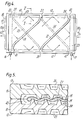
Les intercalaires représentés figures 4 et 5 montrent un autre mooe oe réalisation de la présente invention. La membrane (18, 19) est du type tubulaire aplatie ; elle est parcourue intérieurement par le sang qui, par exemple, pénètre et est évacué par ces orifices axiaux, respectivement (14a) et (15a). Cette membrane a la forme générale d'une poche fermée qui, pour plus de clarté, est représentée figure 4 en traits mixtes, débordant de l'intercalaire (10). En réalité, seuls les orifices (14a) et (15a) s'étendent nettement hors de l'intercalaire (10) et traversent le dispositif d'étanchéité périphérique (12), localement incurvé à leur endroit.The dividers shown in FIGS. 4 and 5 show another embodiment of the present invention. The membrane (18, 19) is of the flattened tubular type; it is traversed internally by the blood which, for example, penetrates and is evacuated by these axial orifices, respectively (14a) and (15a). This membrane has the general shape of a closed pocket which, for clarity, is shown in Figure 4 in phantom, projecting from the interlayer (10). In reality, only the orifices (14a) and (15a) extend clearly out of the interlayer (10) and pass through the peripheral sealing device (12), locally curved in their place.
Les nervures-butées (31) et (34) d'une part, et (32, 33) d'autre part, se recouvrent à leurs extrémités pour former ensemole des butoirs (37) et (38). Ces butoirs correspondent à des excroissances locales internes du dispositif d'étanchéité périphérique (12) et (13), oans ses parties longitudinales. De telles excroissances (39,40, 41, 42) sont disposées notamment aux quatre coins de la zone d'échanges.The ribs-stops (31) and (34) on the one hand, and (32, 33) on the other hand, overlap at their ends to form together bumpers (37) and (38). These stops correspond to local internal protuberances of the peripheral sealing device (12) and (13), in its longitudinal parts. Such protuberances (39, 40, 41, 42) are arranged in particular at the four corners of the exchange zone.
Le liquide de dialyse qui circule par exemple sur la face supérieure de l'intercalaire (10) et d'abord sous la membrane (18, 19), dans le compartiment situé a gauche de la nervure-butée (31), contourne latéralement la membrane puis s'écoule sur celle-ci (voir flèches) en passant par l'orifice (43) ménagé d'une part entre les dispositifs c'étanchéité longitudinaux des intercalaires (10) et (11) et la membrane (16,19) et d'autre part, entre les butoirs (37) et (39).The dialysis liquid which circulates for example on the upper face of the interlayer (10) and first under the membrane (18, 19), in the compartment situated to the left of the stop rib (31), laterally bypasses the membrane and then flows thereon (see arrows) passing through the orifice (43) formed on the one hand between the longitudinal sealing devices of the inserts (10) and (11) and the membrane (16,19 ) and on the other hand, between the stops (37) and (39).
Ainsi l'ensemble du liquide ce dialyse qui s'écoule dans ce premier compartiment, contourne la membrane (18, 19) par un orifice unique. Dans ce mode de réalisation particulier cet orifice ne traverse pas la paroi d'un intercalaire. Il est constitué par une cavité longitudinale étroite telle qu'une rainure disposée à l'intérieur et contre les parties longitudinales du dispositif d'étanchéité périphérique de chaque intercalaire. Par superposition de deux intercalaires, les deux rainures se font face et définissent la cavité constituant l'orifice (43) par lequel le liquide de dialyse contourne la membrane pour s'écouler de la face inférieure à la face supérieure ou vice-versa. Chaque rainure est le plus souvent constituée par l'absence de relief support de membrane à cet endroit. On dispose ainsi d'un nouveau moyen permettant de faire circuler un fluide autour d'une membrane en deux fractions effectuant deux parcours hélicoïdaux aplatis conjoints qui balayent et se croisent sur toute la surface d'échanges, tout en restant à l'intérieur de la zone d'échanges des intercalaires.Thus all of the liquid that dialysis that flows in this first compartment, bypasses the membrane (18, 19 ) by a single orifice. In this particular embodiment, this orifice does not pass through the wall of an interlayer. It consists of a cavity narrow longitudinal such as a groove disposed inside and against the longitudinal parts of the peripheral sealing device of each interlayer. By superposition of two spacers, the two grooves face each other and define the cavity constituting the orifice (43) through which the dialysis liquid bypasses the membrane to flow from the lower face to the upper face or vice versa. Each groove is most often formed by the absence of relief membrane support at this location. There is thus a new means allowing a fluid to circulate around a membrane in two fractions making two helical joint flattened paths which sweep and cross over the entire exchange surface, while remaining inside the dividers interchange area.
Naturellement, si désiré, il est possible, par exemple avec des membranes plànes repliées sur un côté et des intercalaires munis d'orifices sur un côté seulement, de combiner de plusieurs manières les différents modes de réalisation ci-avant décrits et représentés, le liquide de dialyse circulant par exemple en zig-zag, alternativement autour d'une paire de membranes et autour d'un intercalaire.Naturally, if desired, it is possible, for example with flat membranes folded over on one side and spacers provided with orifices on one side only, to combine in several ways the different embodiments described above and represented, the liquid of dialysis circulating for example in a zig-zag, alternately around a pair of membranes and around a spacer.
Naturellement les membranes telles que (18, 19) sont supportées par les intercalaires, outre au moyen des nervures-butées (3l, 32, 33, 34) par des éléments en relief de tous types connus en soi : nervures continues, discontinues, ou multipoints en forme de cônes, pyramides, prismes, ... Par exemple on a représenté figure 1 des nervures continues (35) alternant avec des nervures discontinues (36), parallèles aux nervures-butées (31, 32, 33, 34) et se croisant dos à dos avec les nervures homologues de la face opposée. La disposition relative de ces différents éléments en relief supports de membrane est de type connu en soi. Ces éléments peuvent par exemple être disposés dans le sens général oe l'écoulement du liquide de dialyse, également en zig-zag, ou selon des ondulations.Naturally the membranes such as (18, 19) are supported by the spacers, in addition by means of the ribs-stops (31, 32, 33, 34) by elements in relief of all types known per se: continuous, discontinuous ribs, or multipoints in the form of cones, pyramids, prisms, etc. For example, FIG. 1 shows continuous ribs (35) alternating with discontinuous ribs (36), parallel to the stop ribs (31, 32, 33, 34) and crossing back to back with homologous ribs on the opposite side. The relative arrangement of these various elements in relief membrane supports is of a type known per se. These elements can for example be arranged in the general direction oe the flow of the dialysis liquid, also in a zig-zag, or according to undulations.
Avantageusement ces nervures, continues ou discontinues, qui guident l'écoulement du liquide de dialyse et supportent la membrane, peuvent avoir un profil longitudinal de hauteur non uniforme, comme oécrit dans la demande ce brevet européen 55 680. De même elles peuvent être de hauteurs légèrement différentes, comme décrit, par exemple, dans la demande ae brevet européen 64 931. Ces deux dernières dispositions peuvent si nécessaire être combinées ensemble.Advantageously, these ribs, continuous or discontinuous, which guide the flow of the dialysis liquid and support the membrane, can have a longitudinal profile of non-uniform height, as described in the application European patent 55 680. Similarly, they can be of heights slightly different, as described, for example, in European patent application 64 931. These last two provisions can if necessary be combined together.
Parmi les divers avantages de la nouvelle structure d'intercalaires selon l'invention, on note un excellent soutien des memoranes minces et flexibles, grâce à des jeux de nervures continues et ooliques par rapport au sens d'étirement des membranes. Elles permettent ainsi une redistribution du fluide circulant entre l'intercalaire et la membrane à chaque changement de compartiment, ce qui évite les inconvénients constatés antérieurement, notamment de mise hors circuit d'une rainure à travers toute la zone d'écnanges.Among the various advantages of the new interlayer structure according to the invention, there is excellent support for thin and flexible memorans, thanks to sets of continuous and oolic ribs with respect to the direction of stretching of the membranes. They thus allow a redistribution of the fluid circulating between the interlayer and the membrane at each change of compartment, which avoids the drawbacks noted previously, in particular of switching off a groove through the entire area of interchanges.
On remarque également que la fabrication de ces intercalaires ne pose aucun problème particulier ; que leur maintien en place une fois assemblés en appareils est amélioré par le rôle des nervures-butées qui, en se croisant, constituent par superposition des piliers de hauteur constante ; que l'étanchéité est obtenue par simple serrage des intercalaires et membranes superposées, ce qui conduit à une excellente fiabilité, ainsi qu'à une bonne compacité et à une bonne économie de fabrication et d'emploi.We also note that the manufacture of these spacers poses no particular problem; that their retention in place once assembled into devices is improved by the role of ribs-stops which, by crossing, constitute by superposition of pillars of constant height; that the seal is obtained by simple tightening of the overlapping inserts and membranes, which leads to excellent reliability, as well as good compactness and good economy of manufacture and use.
La forme, le nombre et la disposition relative des nervures-butées telles que (31, 32, 33, 34), ainsi que des orifices tels que (28, 29, 43) peuvent naturellement faire l'objet de nombreuses variantes de réalisation à la portée du technicien sans sortir du cadre oe la présente invention.The shape, number and relative arrangement of the ribs-stops such as (31, 32, 33, 34), as well as orifices such as (28, 29, 43) can naturally be the subject of numerous alternative embodiments to the scope of the technician without departing from the scope of the present invention.
Claims (13)
Applications Claiming Priority (2)
| Application Number | Priority Date | Filing Date | Title |
|---|---|---|---|
| FR8218371 | 1982-10-28 | ||
| FR8218371A FR2535214B1 (en) | 1982-10-28 | 1982-10-28 | SPACER FOR MEMBRANE APPARATUS |
Publications (2)
| Publication Number | Publication Date |
|---|---|
| EP0108025A1 true EP0108025A1 (en) | 1984-05-09 |
| EP0108025B1 EP0108025B1 (en) | 1986-07-30 |
Family
ID=9278843
Family Applications (1)
| Application Number | Title | Priority Date | Filing Date |
|---|---|---|---|
| EP83420165A Expired EP0108025B1 (en) | 1982-10-28 | 1983-10-17 | Spacer plate for a membrane apparatus |
Country Status (6)
| Country | Link |
|---|---|
| US (1) | US4624778A (en) |
| EP (1) | EP0108025B1 (en) |
| JP (1) | JPS59193103A (en) |
| DE (1) | DE3364994D1 (en) |
| FR (1) | FR2535214B1 (en) |
| IE (1) | IE54689B1 (en) |
Cited By (2)
| Publication number | Priority date | Publication date | Assignee | Title |
|---|---|---|---|---|
| WO2014207017A1 (en) * | 2013-06-25 | 2014-12-31 | Tetra Laval Holdings & Finance S.A. | Membrane filtration device having an improved design |
| WO2014207016A1 (en) * | 2013-06-25 | 2014-12-31 | Tetra Laval Holdings & Finance S.A. | Membrane filtration device having a hygienic suspension arrangement |
Families Citing this family (11)
| Publication number | Priority date | Publication date | Assignee | Title |
|---|---|---|---|---|
| GB1442754A (en) * | 1972-06-28 | 1976-07-14 | Nat Res Dev | Apparatus for and method of effecting heat or mass transfer berween fluids |
| DE68922908T2 (en) * | 1989-01-13 | 1995-11-02 | Minntech Corp., Minneapolis, Minn. | WEDGE FOR AN OXYGEN DEVICE. |
| EP0487576B1 (en) * | 1989-08-17 | 1995-02-15 | Brian John Bellhouse | Method and apparatus for effecting the transfer of heat or mass through a membrane involving the use of vortices |
| DE10001880C2 (en) * | 2000-01-19 | 2002-10-31 | Geesthacht Gkss Forschung | spacer |
| FR2931081B1 (en) * | 2008-05-14 | 2010-06-25 | Direction Et Pirorites | DEVICE FOR FILTRATION OF A COMPLEX LIQUID SUCH AS BLOOD, IN PARTICULAR APPLICABLE TO AN AUTOSFUSER |
| CA2817722A1 (en) * | 2010-11-12 | 2012-05-18 | Siemens Pte. Ltd. | Methods of making a cell stack for an electrical purification apparatus |
| US20140183134A1 (en) * | 2013-01-02 | 2014-07-03 | Hydration Systems, Llc | Forward osmosis and pressure retarded osmosis spacer |
| CA2904825A1 (en) | 2013-03-15 | 2014-09-18 | Evoqua Water Technologies Llc | Flow distributors for electrochemical separation |
| US10161690B2 (en) * | 2014-09-22 | 2018-12-25 | Hamilton Sundstrand Space Systems International, Inc. | Multi-layer heat exchanger and method of distributing flow within a fluid layer of a multi-layer heat exchanger |
| US11439948B2 (en) * | 2019-12-09 | 2022-09-13 | Mahle International Gmbh | Membrane module for mitigating evaporative fuel emissions of automobiles |
| CN114593623B (en) * | 2022-03-30 | 2023-10-20 | 内蒙古工业大学 | Heat exchanger capable of automatically adjusting heat exchange area |
Citations (5)
| Publication number | Priority date | Publication date | Assignee | Title |
|---|---|---|---|---|
| FR642884A (en) * | 1927-11-12 | 1928-09-06 | Heibig & Cie | Improvements to pressed filters dialyzers |
| FR997591A (en) * | 1949-02-16 | 1952-01-08 | Creamery Package Mfg Co | plate heat exchanger |
| FR2145860A5 (en) * | 1971-07-15 | 1973-02-23 | Rhone Poulenc Sa | Expanded plastic exchanger plates - suitable for supporting dialysis membranes in artificial kidney machine |
| EP0053084A1 (en) * | 1980-11-13 | 1982-06-02 | Hospal Industrie | Apparatus usable as an artificial kidney, comprising plates with grooves |
| EP0055680A1 (en) * | 1980-12-31 | 1982-07-07 | Hospal Industrie | Apparatus comprising plates provided with ribs having bosses and useful as a hemodialyzer |
Family Cites Families (6)
| Publication number | Priority date | Publication date | Assignee | Title |
|---|---|---|---|---|
| SE314167B (en) * | 1967-05-25 | 1969-09-01 | Gambro Ab | |
| SU396114A1 (en) * | 1967-09-25 | 1973-08-29 | Всесоюзный научно нсследовагельскнй институт хирургической аппаратуры , инструментов | APPARATUS TO REMOVE TOXIC SUBSTANCES FROM THE BLOOD |
| DK142529B (en) * | 1968-10-25 | 1980-11-17 | Danske Sukkerfab | Apparatus for separating liquids into two fractions with greater, respectively smaller contents of a given component than in the starting liquid. |
| US3541595A (en) * | 1969-06-09 | 1970-11-17 | Miles Lowell Edwards | Membrane fluid diffusion exchange device |
| SE390109B (en) * | 1973-09-13 | 1976-12-06 | Paul J Johansson | DIALYSIS DEVICE FOR PURIFICATION OF A MEDIUM, PREFERABLY BLOOD |
| FI55446C (en) * | 1976-07-02 | 1979-08-10 | Enso Gutzeit Oy | SKIVFILTER |
-
1982
- 1982-10-28 FR FR8218371A patent/FR2535214B1/en not_active Expired
-
1983
- 1983-09-27 IE IE2272/83A patent/IE54689B1/en unknown
- 1983-10-17 DE DE8383420165T patent/DE3364994D1/en not_active Expired
- 1983-10-17 EP EP83420165A patent/EP0108025B1/en not_active Expired
- 1983-10-24 US US06/544,999 patent/US4624778A/en not_active Expired - Fee Related
- 1983-10-28 JP JP58201165A patent/JPS59193103A/en active Pending
Patent Citations (5)
| Publication number | Priority date | Publication date | Assignee | Title |
|---|---|---|---|---|
| FR642884A (en) * | 1927-11-12 | 1928-09-06 | Heibig & Cie | Improvements to pressed filters dialyzers |
| FR997591A (en) * | 1949-02-16 | 1952-01-08 | Creamery Package Mfg Co | plate heat exchanger |
| FR2145860A5 (en) * | 1971-07-15 | 1973-02-23 | Rhone Poulenc Sa | Expanded plastic exchanger plates - suitable for supporting dialysis membranes in artificial kidney machine |
| EP0053084A1 (en) * | 1980-11-13 | 1982-06-02 | Hospal Industrie | Apparatus usable as an artificial kidney, comprising plates with grooves |
| EP0055680A1 (en) * | 1980-12-31 | 1982-07-07 | Hospal Industrie | Apparatus comprising plates provided with ribs having bosses and useful as a hemodialyzer |
Cited By (4)
| Publication number | Priority date | Publication date | Assignee | Title |
|---|---|---|---|---|
| WO2014207017A1 (en) * | 2013-06-25 | 2014-12-31 | Tetra Laval Holdings & Finance S.A. | Membrane filtration device having an improved design |
| WO2014207016A1 (en) * | 2013-06-25 | 2014-12-31 | Tetra Laval Holdings & Finance S.A. | Membrane filtration device having a hygienic suspension arrangement |
| US9776138B2 (en) | 2013-06-25 | 2017-10-03 | Tetra Laval Holdings & Finance S.A. | Membrane filtration device having a hygienic suspension arrangement |
| US10005037B2 (en) | 2013-06-25 | 2018-06-26 | Tetra Laval Holdings & Finance S.A. | Memrane filtration device having an improved design |
Also Published As
| Publication number | Publication date |
|---|---|
| IE832272L (en) | 1984-04-28 |
| US4624778A (en) | 1986-11-25 |
| DE3364994D1 (en) | 1986-09-04 |
| JPS59193103A (en) | 1984-11-01 |
| IE54689B1 (en) | 1990-01-03 |
| EP0108025B1 (en) | 1986-07-30 |
| FR2535214A1 (en) | 1984-05-04 |
| FR2535214B1 (en) | 1987-06-12 |
Similar Documents
| Publication | Publication Date | Title |
|---|---|---|
| EP0108025B1 (en) | Spacer plate for a membrane apparatus | |
| EP1206672B1 (en) | Heat exchanger and related exchange module | |
| FR2486812A1 (en) | APPARATUS, CONSISTING OF SUPPORT PLATES AND PIECES OF A SEMI-PERMEABLE MEMBRANE, FOR THE SEPARATION OF FLUIDS | |
| EP1825918A1 (en) | Circular centrifuge chamber for the separation of blood | |
| WO2010079455A2 (en) | Rotors for rotating electrical machines | |
| FR2653031A1 (en) | ||
| WO2005116436A1 (en) | Heat exchanger with plates | |
| FR3055951B1 (en) | ENTHALPIC EXCHANGER WITH SIMPLIFIED DESIGN | |
| FR2647198A1 (en) | Plate pipe heat exchanger | |
| EP0053084B1 (en) | Apparatus usable as an artificial kidney, comprising plates with grooves | |
| CA2386372C (en) | Continuous casting roll for metal strip comprising a cooling circuit | |
| EP0014166A1 (en) | Medical membrane apparatus for exchanging and/or separating liquids, application thereof to the treatment of blood and a blood treatment circuit comprising such an apparatus | |
| EP3155344B1 (en) | Plate heat exchanger | |
| CH627086A5 (en) | Process for the manufacture of a mass transfer apparatus | |
| EP0495973B1 (en) | Method and device for splitting a stream of fluid | |
| EP0553340B1 (en) | Plate-type heat exchanger | |
| CH623746A5 (en) | Mass transfer apparatus with a semipermeable membrane | |
| FR2534485A1 (en) | Insert for membrane apparatus | |
| EP0055680B1 (en) | Apparatus comprising plates provided with ribs having bosses and useful as a hemodialyzer | |
| FR2643268A1 (en) | Apparatus for treatment of fluids with a plane membrane | |
| WO2017109350A1 (en) | Heat exchanger, notably for motor vehicle | |
| FR2584609A1 (en) | Method for heat exchange between blood and a heat-exchange fluid and heat exchanger making use thereof | |
| FR2533021A1 (en) | Plate heat exchanger. | |
| FR2641066A1 (en) | Improvement to fluid condenser tubes with longitudinal fins and condensers using such tubes | |
| FR2536999A1 (en) | Exchange device of the dialyser type |
Legal Events
| Date | Code | Title | Description |
|---|---|---|---|
| PUAI | Public reference made under article 153(3) epc to a published international application that has entered the european phase |
Free format text: ORIGINAL CODE: 0009012 |
|
| AK | Designated contracting states |
Designated state(s): BE CH DE GB IT LI NL SE |
|
| 17P | Request for examination filed |
Effective date: 19840922 |
|
| ITF | It: translation for a ep patent filed | ||
| GRAA | (expected) grant |
Free format text: ORIGINAL CODE: 0009210 |
|
| AK | Designated contracting states |
Kind code of ref document: B1 Designated state(s): BE CH DE GB IT LI NL SE |
|
| REF | Corresponds to: |
Ref document number: 3364994 Country of ref document: DE Date of ref document: 19860904 |
|
| PLBE | No opposition filed within time limit |
Free format text: ORIGINAL CODE: 0009261 |
|
| STAA | Information on the status of an ep patent application or granted ep patent |
Free format text: STATUS: NO OPPOSITION FILED WITHIN TIME LIMIT |
|
| 26N | No opposition filed | ||
| PG25 | Lapsed in a contracting state [announced via postgrant information from national office to epo] |
Ref country code: SE Effective date: 19891018 |
|
| ITTA | It: last paid annual fee | ||
| PG25 | Lapsed in a contracting state [announced via postgrant information from national office to epo] |
Ref country code: LI Effective date: 19891031 Ref country code: CH Effective date: 19891031 |
|
| PGFP | Annual fee paid to national office [announced via postgrant information from national office to epo] |
Ref country code: NL Payment date: 19891031 Year of fee payment: 7 Ref country code: GB Payment date: 19891031 Year of fee payment: 7 |
|
| PGFP | Annual fee paid to national office [announced via postgrant information from national office to epo] |
Ref country code: BE Payment date: 19891115 Year of fee payment: 7 |
|
| PGFP | Annual fee paid to national office [announced via postgrant information from national office to epo] |
Ref country code: DE Payment date: 19891215 Year of fee payment: 7 |
|
| REG | Reference to a national code |
Ref country code: CH Ref legal event code: PL |
|
| PG25 | Lapsed in a contracting state [announced via postgrant information from national office to epo] |
Ref country code: GB Effective date: 19901017 |
|
| PG25 | Lapsed in a contracting state [announced via postgrant information from national office to epo] |
Ref country code: BE Effective date: 19901031 |
|
| BERE | Be: lapsed |
Owner name: HOSPAL INDUSTRIE Effective date: 19901031 |
|
| PG25 | Lapsed in a contracting state [announced via postgrant information from national office to epo] |
Ref country code: NL Effective date: 19910501 |
|
| GBPC | Gb: european patent ceased through non-payment of renewal fee | ||
| NLV4 | Nl: lapsed or anulled due to non-payment of the annual fee | ||
| PG25 | Lapsed in a contracting state [announced via postgrant information from national office to epo] |
Ref country code: DE Effective date: 19910702 |
|
| EUG | Se: european patent has lapsed |
Ref document number: 83420165.9 Effective date: 19900706 |