EP0107722B1 - System for forming an image on the surface of a plastic card - Google Patents
System for forming an image on the surface of a plastic card Download PDFInfo
- Publication number
- EP0107722B1 EP0107722B1 EP83901873A EP83901873A EP0107722B1 EP 0107722 B1 EP0107722 B1 EP 0107722B1 EP 83901873 A EP83901873 A EP 83901873A EP 83901873 A EP83901873 A EP 83901873A EP 0107722 B1 EP0107722 B1 EP 0107722B1
- Authority
- EP
- European Patent Office
- Prior art keywords
- card
- image
- toner image
- electrophotographic medium
- set forth
- Prior art date
- Legal status (The legal status is an assumption and is not a legal conclusion. Google has not performed a legal analysis and makes no representation as to the accuracy of the status listed.)
- Expired
Links
Images


Classifications
-
- H—ELECTRICITY
- H04—ELECTRIC COMMUNICATION TECHNIQUE
- H04N—PICTORIAL COMMUNICATION, e.g. TELEVISION
- H04N1/00—Scanning, transmission or reproduction of documents or the like, e.g. facsimile transmission; Details thereof
- H04N1/23—Reproducing arrangements
- H04N1/29—Reproducing arrangements involving production of an electrostatic intermediate picture
-
- G—PHYSICS
- G01—MEASURING; TESTING
- G01D—MEASURING NOT SPECIALLY ADAPTED FOR A SPECIFIC VARIABLE; ARRANGEMENTS FOR MEASURING TWO OR MORE VARIABLES NOT COVERED IN A SINGLE OTHER SUBCLASS; TARIFF METERING APPARATUS; MEASURING OR TESTING NOT OTHERWISE PROVIDED FOR
- G01D15/00—Component parts of recorders for measuring arrangements not specially adapted for a specific variable
- G01D15/06—Electric recording elements, e.g. electrolytic
-
- G—PHYSICS
- G03—PHOTOGRAPHY; CINEMATOGRAPHY; ANALOGOUS TECHNIQUES USING WAVES OTHER THAN OPTICAL WAVES; ELECTROGRAPHY; HOLOGRAPHY
- G03G—ELECTROGRAPHY; ELECTROPHOTOGRAPHY; MAGNETOGRAPHY
- G03G15/00—Apparatus for electrographic processes using a charge pattern
- G03G15/14—Apparatus for electrographic processes using a charge pattern for transferring a pattern to a second base
- G03G15/16—Apparatus for electrographic processes using a charge pattern for transferring a pattern to a second base of a toner pattern, e.g. a powder pattern, e.g. magnetic transfer
- G03G15/1625—Apparatus for electrographic processes using a charge pattern for transferring a pattern to a second base of a toner pattern, e.g. a powder pattern, e.g. magnetic transfer on a base other than paper
-
- G—PHYSICS
- G06—COMPUTING OR CALCULATING; COUNTING
- G06K—GRAPHICAL DATA READING; PRESENTATION OF DATA; RECORD CARRIERS; HANDLING RECORD CARRIERS
- G06K19/00—Record carriers for use with machines and with at least a part designed to carry digital markings
- G06K19/06—Record carriers for use with machines and with at least a part designed to carry digital markings characterised by the kind of the digital marking, e.g. shape, nature, code
- G06K19/06009—Record carriers for use with machines and with at least a part designed to carry digital markings characterised by the kind of the digital marking, e.g. shape, nature, code with optically detectable marking
- G06K19/06046—Constructional details
-
- G—PHYSICS
- G07—CHECKING-DEVICES
- G07C—TIME OR ATTENDANCE REGISTERS; REGISTERING OR INDICATING THE WORKING OF MACHINES; GENERATING RANDOM NUMBERS; VOTING OR LOTTERY APPARATUS; ARRANGEMENTS, SYSTEMS OR APPARATUS FOR CHECKING NOT PROVIDED FOR ELSEWHERE
- G07C9/00—Individual registration on entry or exit
- G07C9/20—Individual registration on entry or exit involving the use of a pass
- G07C9/22—Individual registration on entry or exit involving the use of a pass in combination with an identity check of the pass holder
- G07C9/25—Individual registration on entry or exit involving the use of a pass in combination with an identity check of the pass holder using biometric data, e.g. fingerprints, iris scans or voice recognition
- G07C9/253—Individual registration on entry or exit involving the use of a pass in combination with an identity check of the pass holder using biometric data, e.g. fingerprints, iris scans or voice recognition visually
Definitions
- This invention relates to a method of forming an image on a plastic card comprising digitizing an image to generate a digital image signal.
- the invention relates to a system for forming an image on plastic card, comprising means for receiving a digital image signal.
- One other prior art system for forming images on plastic cards is a system in which a silk screened ink patch is placed on the surface of a plastic card and an image is etched on the silk screened ink patch using an electronically actuated mechanical scribe.
- scribing systems do not have the capability of correlating image data and alphanumeric data for placement of corresponding indicia on a single plastic card.
- the scribing system is relatively slow, making, it unacceptable in an overall system in which embossing and encoding is also to be performed.
- it is necessary to provide a silk screened ink patch on each card it is not possible to use conventional plastic cards, thereby resulting in an increased cost per card.
- the grooves which are present in scribed images are susceptible to the collection of dirt in a wallet environment, thereby resulting in a relatively non-durable card.
- US ⁇ A ⁇ 4,175,851 teaches a recording position adjuster.
- the device includes a beam modulator and transferring means that requires a paper base material for receiving the image and does not teach transferring an image directly from an electrophotographic medium to a card.
- the device comprises positioning means including a reference signal and an address counter for measuring the time from generation of the signal until the time that the image should be conveyed and transferred to the base material.
- US-A-4,233,612 teaches an image information electrostatic, recording device.
- the patent requires a paper base and a photosensitive body consisting of insulative layer, thermal conductive layer, and electrically conductive substrate.
- the patent does not teach direct transference to a card from an electrophotographic medium. Two charges must be applied to the photosensitive body for transferring the image. The image is transferred electrostatically, heat and pressure are not used to transfer the image to the photosensitive body.
- US-A-4.,217,819 teaches a device for the transfer process of characters, consisting of toner, that are applied to a continuously rotating band- shaped intermediate carrier.
- the patent teaches a rotating elastic band for carrying toner in a copying machine. The band is clamped down to apply the image to the base material which must be a sheet-like paper material.
- the patent cannot be used for applying the images to a plastic card without a paper base.
- the patent teaches only intermediate carrying of toner and does not teach modulation of a beam or actual application of an image to a card.
- An object of the present invention is to provide a method and a system for forming an image on a plastic card which overcomes the deficiencies of prior art systems.
- a further object of this invention is to provide a system in which image data representing an image is correlated with corresponding alphanumeric data representing indicia which is to be embossed and/or encoded on the card.
- a further object of this invention is to provide a system which produces card having a durable image.
- a further object of this invention is to provide a system in which the time-required for forming the image is substantially the same as or less than the time required for embossing and/or encoding the card.
- a still further object of this invention is to provide a system for producing a high resolution image on the card.
- the system of the present invention has a number of novel features as set forth below.
- An image is digitized and stored in semi-permanent storage together with corresponding alphanumeric data representing, for example, indicia to be embossed and/or encoded on a card.
- the digital image data is read from the semi-permanent storage and is input to an acousto-optic modulator.
- the acousto-optic modulator modulates a coherent light beam in accordance with the digital image data and the modulated coherent light beam is scanned across a charged electrophotographic medium, thereby producing a latent electrostatic image (corresponding to the image to be formed on the card) on the electrophotographic medium.
- the electrophotographic medium is transported past a toning station and a toner image (corresponding to the latent electrostatic image) is formed on the electrophotographic medium.
- the toner image is positioned adjacent a card to which the image is to be transferred and the electrophotographic medium is then pressed against the card so as to transfer the toner image to the card through heat and pressure.
- the electrophotographic medium is peeled away from the card so that the fused toner image remains on the' card.
- a plastic overlay which is substantially the same size as the image on the card may be overlayed to provide additional protection for the image.
- the system of the present invention has significant advantages over the prior art in that conventional plastic cards may be used, so that cheaper and more readily available unprocessed plastic cards may be employed.
- the system of the present invention does not slow down the throughput of the plastic card manufacturing process since the time for forming the image on the card is comparable to the time required for embossing and encoding operations.
- the storage of digital data comprising image data and corresponding alphanumeric data, allows for simple and accurate processing of all of the information which must be provided for each cardholder.
- FIG 1 illustrates the data acquisition subsystem of the present invention.
- a video camera 20 is employed to take a picture of a subject or cardholder 22 for whom a card 24 ( Figure 3) is to be formed.
- the video camera is the RCA Model No. 2055 Vidicon camera which is a source of a live video picture.
- the card 24 which is to be generated for each cardholder 22 may be, for example, a plastic credit card, a driver's license, or any other type of identification card which is suitable for manufacture in the system of the present invention. For convenience, reference is made hereinafter to a "card" 24.
- a video digitizer 26 receives an analog image signal from the camera 20 and generates a digital image signal, wherein each digital word represents a gray level of a small portion of the image.
- a graphics memory and refresh control circuit 28 receives the digital image signal from the video digitizer 26 and generates an analog video signal for a CRT display 30 which displays an image of the subject 22.
- the graphics memory and refresh control circuit 28 is also connected to a microprocessor and memory circuit 32 for transmitting and receiving the digital data signal along a bi-directional data bus 33 and for receiving an address signal as well as input/output read and write signals.
- the microprocessor and memory 32 may be connected to a remote computer or microprocessor via a standard RS-232C link.
- a keyboard 34 is also connected to the microprocessor and memory 32 so that alphanumeric data (e.g., embossing data, name and address information, account information, encoding information, and other identifying information) can be input to the microprocessor and memory 32.
- This alphanumeric data is correlated with the corresponding digital image data and temporarily stored in the graphics memory and refresh control circuit 28 and displayed on CRT display 30.
- the microprocessor and memory 32 is also connected to semi-permanent storage 36 so that the alphanumeric and digital image data which is temporarily stored in the graphics memory and refresh control circuit 28 may be output to the semi-permanent storage 36 for later retrieval.
- the microprocessor and memory 32 controls the operation of the data acquisition subsystem and includes a processor 38, a PROM (programmable read only memory) 40, a RAM (random access memory) 42 and an input/output selection circuit 44.
- the PROM 40 stores the control program for the processor 38.
- the RAM 42 provides temporary storage for the digital picture data and alphanumeric data during transfer of data to the semi-permanent storage 36.
- the I/O selection circuit 44 controls the input and output of data to and from the microprocessor and memory 32.
- the keyboard 34 comprises an alphanumeric refresh memory 46, a CRT controller 48, a character (dot) generator 50 and keyboard switches 52.
- the central processor 38 When one of the keyboard switches 52 is depressed, the central processor 38 is interrupted and the processor 38 reads the ASCII character from the keyboard 34 and stores it in the RAM 42.
- the character generator 50 decodes the keyboard character and sends a dot pattern, corresponding to the one of the keyboard switches 52 which has been depressed, to the CRT controller 48. This dot pattern is stored in the alphanumeric refresh memory 46 and the CRT display 30 continuously displays the dot pattern until the alphanumeric refresh memory 46 is altered or cleared.
- the video camera 20 and video digitizer 26 capture a live field of video from the camera within at least 1/30th of a second.
- the video digitizer 26 is a fully parallel (flash) analog-to-digital (A/D) converter.
- the graphics memory and refresh control circuit 28 includes a control timing circuit 54, a picture memory 56 and a digital-to-analog converter 58.
- the control timing circuit 54 samples the output of the video digitizer 26 at a rate which will yield a one-to-one aspect ratio.
- the sampled data is stored in the picture memory 56 and is used to refresh the CRT display 30 which displays the picture.
- the video camera 20 provides horizontal and vertical synchronization pulses for aligning the image displayed on the CRT display 30 with what the camera views. After the vertical retrace interval of the video camera 20, the control timing circuit 54 initializes the picture memory 56 to begin storing new camera data.
- the last digitized field of camera video is "frozen" in the picture memory 56 and may then be accessed by the microprocessor and memory 32 which receives the stored picture.
- the microprocessor and memory 32 performs various processing routines to improve the quality of the image.
- the picture is compressed to reduce the amount of data necessary to represent the picture to be stored on the semi-permanent storage 36.
- the alphanumeric data which is input via the keyboard 34 is correlated with the digital picture data received from the picture memory 56 in the RAM 42.
- the correlated alphanumeric data and digital image data are temporarily stored in the RAM 42 and the digital words representing the image data are placed in specific memory locations representing the location of the picture element (pixel) whose gray level is the content of that memory element.
- the image is digitized so that the gray level in each discrete picture element is stored in memory locations representing the actual location in the visual image.
- the corresponding alphanumeric data is stored in adjacent memory locations to identify the images corresponding to the data.
- the image data which is stored will correspond to the combined image (picture plus alphanumeric data) which is generated on the CRT display 30.
- a convenient check on the correspondance between the alphanumeric data which is formed (e.g., embossed) on the card and the image which is formed on the card may be made.
- the central processor 38 outputs the stored data on the bi-directional data bus 33 to the semi-permanent storage 36.
- the semi-permanent storage 36 includes a cassette interface and a magnetic tape cassette on which digital data is stored during the data acquisition phase of the present system.
- the data stored on the magnetic tape for each card to be manufactured includes digital image (i.e. picture) data, print data, magnetic stripe data and emboss/encode data.
- the print data, emboss/encode data and magnetic stripe data are transmitted to an embosser/encoder 60 (Fig. 5).
- the system of the present invention may be operated “in line” with any automatic embossing system, and preferably with an automatic embossing system manufactured by Data Card Corporation.
- the system of the present invention may be operated “in line” with the Data Card Series 4000 embosser/encoder described in U.S. Patent 4,088,216, assigned to the assignee of the present application, or the Data Card Series 1500 embosser described in U.S. Patent Re 27,809, assigned to the assignee of the present application.
- the system of the present invention may be used as a stand-alone system to fully image a card with alphanumeric data, picture(s), signature(s) and the like.
- FIG. 3 is a right side elevational view of the overall image generating and transfer subsystem of the present invention.
- a supply roll 64 holds a roll supply of an electrophotographic medium 66 which in the preferred embodiment is electrophotographic film.
- a selenium drum is employed as the electrophotographic medium 66.
- the electrophotographic film 66 is drawn around a roller 68 and past a sensitizing station comprising a corona generator 70 for placing a charge on the surface of the electrophotographic film 66.
- the sensitized film 66 is transported past an exposure station 72 and a toning station 74.
- the exposure station 72 generates a modulated laser beam which is scanned across the sensitized electrophotographic film 66.
- the film 66 As the film 66 is transported past the toning station 74, charged toner is attracted to the scanned portions of the film 66, so that a toner image is formed on the film 66.
- the film 66, carrying the toner image is transported around a pair of rollers 76 and 78 which orient the film 66 so that an air knife 80 can remove any loose toner particles and residual solvent which are carried by the film 66.
- the film 66 is transported around a roller 62 which is spring biased by a spring 64 to form a buffer loop, which provides a flexible film interface between the image development portion of the system, which operates at substantially constant film velocity, and the image transfer portion of the system which operates with incremental motion.
- a pair of rollers 86 and 88 are employed to position the toner image carrying film 66 in a transfer station 90.
- the transfer station 90 comprises a card back up block 92 and a heated platen 94. After the film is transported through the transfer station 90 and the toner image is transferred from the film 66 to the card 24, the film 66 is transported to a take up roll 96 where it is stored for disposal.
- the electrophotographic medium 66 comprises electrophotographic film 66.
- the electrophotographic film 66 comprises a support base 98, a thin conductive layer 100 which is grounded to the film spool (not shown) and a photoconductive layer 102 which has a high dark resistance.
- the corona generator 70 comprises a thin wire 104 and a conducting enclosure 106.
- the film 66 is sensitized (i.e., made light sensitive) by generating a voltage of 3,500 volts or more between the wire 104 and the enclosure 106. This high voltage causes the surrounding air to ionize, thereby causing positive ions to be attracted to the photoconductive layer 102 of the film 66.
- the corona generator 70 is employed to place a uniform electrostatic charge on the surface of the film 66.
- the exposure station 72 of Figure 3 will be described.
- the exposure station 72 may be directly connected to the data acquisition subsystem illustrated in Figure 1.
- digital image data are alphanumeric data can be stored on magnetic tape at a remote location (using the data acquisition subsystem of Figure 1) and the magnetic tape can then be transported to a location for manufacturing a plurality of cards 24.
- the data acquisition subsystem of Figure 1 is employed at remoate locations to store digital image data and alphanumeric data for a plurality of subjects 22.
- the stored digital image data and alphanumeric data is then transported (e.g., either physically, as a magnetic tape or disk, or over phone lines) to a site having complete facilities for manufacturing cards (including, e.g., an embosser/encoder, a card attaching system, etc.) where the information stored on the magnetic tape is read by a tape reader 108.
- the tape reader 108 provides both alphanumeric data and digital image data to a microprocessor 110 which in turn provides the alphanumeric data to the embosser/ encoder 60 and supplies the digital image data to the exposure station 72.
- the microprocessor 110 and tape read 108 are not required since the microprocessor and memory 32 and the semi-permanent storage 36 perform these functions.
- the exposure station 72 comprises a laser 112, powered by its own power supply 114, for generating a coherent light beam 116, hereinafter referred to as laser beam 116.
- the laser 112 is a Hughes model 3225 H-PC 5MW HeNe laser.
- a beam compressor lens 118 compresses the laser beam 116 and feeds the laser beam 116 to an acousto-optic modulator 120.
- the acousto-optic modulator 120 is connected to the microprocessor 110 to receive the digital image data.
- the acousto-optic modulator 120 digitally modulates the laser beam 116, in accordance with the digital image data, to generate a modulated laser beam 122 which is passed through a pair of beam expander lenses 124 and 126 and an objective lens 128.
- the beam expander lenses 124 and 126 expand the modulated laser beam 122 to achieve smaller spot sizes at the plane of the film 66.
- the modulated laser beam 122 passes from the objective lens 128 to a deflection mirror 130 which is oscillated by a galvanometer 132 under the control of deflection control electronics 134.
- the modulated laser beam 122 is scanned back and forth across the plane of the film 66 in the direction of the arrows A and B in Figure 5.
- the acousto-optic modulator 120 comprises an isomet 1205C or 1206C acousto-optic modulator;
- the galvanometer 132 comprises a General Scanning S-230-08 galvanometer;
- the deflection control electronics 134 comprises a General Scanning Model AX-700 galvanometer controller.
- the impingement of the laser beam 122 upon the photoconductive layer 102 causes the positive ions which are attracted to the surface of the photoconductive layer 102 to be conducted to the thin conductive layer 100.
- a latent electrostatic image is formed on the surface of the photoconductive layer 102.
- This image has a resolution of 125 pixels per inch and requires an exposure time of 1/60th second.
- the image is broken down into 2,425 pixels per square cm, each pixel being .02 cm 2 with 64 possible dot positions.
- a varying gray scale is achieved by selectively exposing the dot positions within each pixel.
- the electrophotographic film 66 is Kodak SO-112 electrophotographic film and the toner which is used to tone the film is Kodak MX-1112 or MX-1125 liquid toner.
- the toner which is positively charged in the preferred embodiment
- a toner image 136 ( Figure 7) is formed on the surface of the electrophotographic film 66.
- the heated platen 94 includes a contact area 138 having dimensions which are substantially the same as the toner image 136 which is to be transferred to the card 24.
- This contact area 138 (and hence the image 136) may be any desired size and, for example, may be of a size to occupy the upper right hand corner of the card 24.
- the card back up block 92 is fixed to a support 140 and includes upper and lower card guides 142 and 144, respectively, for confining the position of the card 24 against the surface of the card back up block 92.
- Driven rollers 146 are employed to transport the card 24 into an image transfer position on the card back up block 92 and a vacuum conduit 148 is selectively actuated to hold the card in position against the card back up block 92.
- the heated platen 94 is moved in the direction of arrow C in Figure 8A so that the contact area 138 of the heated platen 94 presses the support base 98 of the electrophotographic film 66, thereby pressing the toner image 136 against the card 24 ( Figure 8B).
- the heated platen 94 dwells at this contact position for a predetermined period of time and is then withdrawn in the direction of arrow D in Figure 8B.
- the toner image 136 In order to achieve the desired transfer of the toner image 136 to the card 24, it is necessary to hold the card 24 flat while the electrophotographic film is pulled away in a peeling motion.
- the peeling motion creates a very high stress at the interface of the peeled material (i.e., the electrophotographic film 66) with the toner. Since the toner is fused by the heat and pressure generated by the contact area 138 of the platen 94, and because of the elastic properties of the fused toner, the stress diminishes through the toner layer to the card 24. Thus, any break or separation will occur at the point of the highest stress, which is the point at which the electrophotographic film 66 and the toner image 136 interface.
- the transfer station 90 is adapted to peel the electrophotographic film 66 from the card 24 and toner image 136.
- the electrophotographic film 66 follows a path denoted by the dashed line F in Figure 8A.
- the roller 88 is connected to a link 150 which pivots about a pivot point 152.
- the roller 88 is biased to the position illustrated by the solid lines in Figure 8A by a bias spring 154 which is connected to a support 155 and to an end 156 of the link 150.
- the pressure of the platen 94 against the card 24 was varied from 620 to 3858 kPa, while holding the platen temperature and dwell time constant at 204°C and 400 ms, respectively.
- the acceptable pressure range was determined to be from 2480 to 3858 kPa. Decreasing the platen pressure caused a greater sensitivity to the platen squareness and thickness, thereby causing partial image drop outs (i.e., partial non-transfer) as well as greater sensitivity to partial image drop outs or flaws due to dust particles. Increasing the platen pressure caused plastic card deformation behind the area where the card 24 contacted the toner image 136.
- the temperature of the platen 94 was varied from 130 to 271°C while maintaining the platen pressure and dwell time constant at 3858 kPa and 400 ms, respectively.
- the acceptable temperature range was determined to be from 182 to 213°C.
- the low temperature range of from 130 to 154°C produced nonuniform, poor transfer characteristics.
- the acceptable temperature range of 182 to 213°C produced excellent transfer characteristics and little mechanical distortion of the card.
- the high temperature range of 213 to 271°C caused severe card distortion and some transfer of the film dye, giving the image formed on the card 24 a blue hue.
- the photoconductive layer 102 separated from the electrophotographic film 66.
- the dwell time of the platen 94 was varied from 50 ms to 1 second while maintaining the platen pressure and temperature constant at 3445 kPa and 204°C, respectively.
- the acceptable range for the dwell time was determined to be from 50 ms to 600 ms. This dwell time produced excellent image transfer, however, card distortion behind the image area increased from insignificant at a 50 ms dwell to severe at a 600 ms dwell. However, the card distortion up to 600 ms is acceptable. Dwell times greater than 600 ms produced separation and transfer of the photoconductive layer 102 to the card 24.
- the heated transfer platen 94 of the present invention provides significant advantages over prior art image transfer devices such as heated rollers.
- no visible heat marks remain on the card in areas other than the image area, so that the surface finish of the remaining portions of the card 24 remains intact.
- the card 24 may be embossed and/or encoded prior to image transfer since the platen 94 presses only on those portions of the card 24 which are to receive the image 136.
- the platen 94 will not damage any prior embossing, nor will it damage any sensitive surfaces such as magnetic stripes which are frequently placed on the back of the card 24.
- a protective layer is placed over the image 136 in order to make the image more able to withstand the abrasion and chemicals present in the wallet environment.
- a protective layer transfer station 158 which is similar to the transfer station 90 is illustrated.
- a carrier film 160 carries a plurality of thin thermoplastic coatings 162 which are approximately the same size as the toner image 136 which is transferred to the card 24.
- the path of the carrier film 160 is defined by rollers 164, 166 and 168.
- a heated platen 170 includes a contact area 172 for contacting the carrier film 160 on the side opposite the thermoplastic coating 162.
- a card back up block 174 is mounted on a support 176 and includes upper and lower card guides 178 and 180, respectively.
- a vacuum conduit 182 provides a selectively actuated source of vacuum for maintaining the card 24 against the card back up block 174.
- Driven rollers 184 are driven to transport the card 24 into and out of the protective layer transfer station 158.
- the heated platen 170 is actuated in the same manner as the heated platen 94 in the transfer station 90.
- the roller 166 is connected to a link 186 which is pivoted about pivot point 188 by a solenoid 190, so that the carrier film 160 is peeled from the thermoplastic coating 162 in the same manner in which the electrophotographic film 66 is peeled from the card 24.
- the thermoplastic coating 162 is 381 millionths of a cm thick and the carrier film 160 is .005 cm thick.
- a preferred minimum pressure of 1100 kPa and a platen temperature of from 160 to 216°C is applied.
- the video camera 20 takes a picture of each cardholder 22, and the picture is then digitized by the video digitizer circuit 26 and sent to the graphics memory and refresh control circuit 28.
- the image which is captured by the camera 20 is displayed on the CRT display 30 and the digital image data is transferred from the graphics memory and refresh control circuit 28 to the microprocessor and memory 32.
- alphanumeric data is input to the microprocessor and memory 32 via the keyboard 34.
- the alphanumeric data may also be displayed on the CRT display.
- the corresponding digital image data and alphanumeric data are stored in the microprocessor and memory 32 and are then transferred to the semi-permanent storage 36.
- the tape reader 108 reads the alphanumeric data and digitial image data from the semi-permanent storage 36 (e.g., magnetic tape) and transmits this data to the microprocessor 110.
- the microprocessor 110 sends the alphanumeric data to the embosser/ encoder 60 and the digital image data to the acousto-optic modulator 120 which is a part of the exposure station 72.
- the electrophotographic film 66 is transported past the sensitizing station 70 where the electrophotographic film 66 is uniformly charged.
- the charged electrophotographic film 66 is transported past the exposure station 72 where the modulated laser beam 122 (modulated in accordance with the digital image data) is scanned across the charged electrophotographic film 66 by the deflection mirror 130, so as to .selectively discharge portions of the electrophotographic film 66 in accordance with the digital image data received by the acousto-optic modulator 120.
- the film 66 carries a latent electrostatic image.
- the selectively discharged electrophotographic film 66 is transported past a toning station 74 where charged toner is attracted to the discharged portions of the electrophotographic film 66, so that the toner image 136 (Fig.
- the electrophotographic film 66 is transported past the air knife 80 so as to remove any loose toner from the toner image 136, and is subsequently transported to a position in between the heated platen 94 and the card 24 which is supported by the card back-up block 92.
- the card 24 has been embossed and/or encoded by the embosser/encoder 60 in accordance with the alphanumeric data corresponding to the toner image which is to be transferred to the card 24.
- the toner image 136 is pressed against the card 24 by the platen 94 ( Figures 8A-8C) to transfer the toner image 136 to the card 24.
- the electrophotographic film 66 is peeled away from the card 24 so that the toner image 136 remains intact on the card 24.
- the card 24 carrying the toner image 136 is then transported to the protective layer transfer station 158 where the thermoplastic coating 162 is transferred to the card 24 to protect the toner image 136 from degradation due to the abrasion and chemicals in a wallet environment.
- the card 24 (carrying the image and embossing/encoding) may be transported to the card attaching system 62 where the card is attached to a carrier having corresponding cardholder indicia printed thereon.
- the system of the present invention may be implemented in numerous ways.
- any type of electrophotographic medium such as a selenium drum, may be used as the electrophotographic medium 66.
- the electrophotographic medium 66 may be charged or discharged in any desired manner, with the corresponding charged toner (i.e. positive or negative) being used to tone the charged or discharged areas.
- the card 24 may be embossed and/or encoded before or after the image is formed on the card; and, if desired, embossing or encoding can be omitted if the image includes the alphanumeric data as a part thereof.
- the values of heat, pressure and dwell time employed to transfer the toner image 136 to the surface of the card 24 may be varied in accordance with the requirements of a particular application. Further, although the card used in the above experiments was composed of polyvinyl chloride, the card 24 may be made of any suitable material to which the toner can be fused.
Landscapes
- Physics & Mathematics (AREA)
- General Physics & Mathematics (AREA)
- Engineering & Computer Science (AREA)
- Human Computer Interaction (AREA)
- Theoretical Computer Science (AREA)
- Multimedia (AREA)
- Signal Processing (AREA)
- Credit Cards Or The Like (AREA)
- Printing Methods (AREA)
- Combination Of More Than One Step In Electrophotography (AREA)
Abstract
Description
- This invention relates to a method of forming an image on a plastic card comprising digitizing an image to generate a digital image signal. The invention relates to a system for forming an image on plastic card, comprising means for receiving a digital image signal.
- There exist, in the prior art, systems for laminating over photographs placed in a cut-out in the inner core stock of a plastic card, and systems for laminating over an electrophotographic or printed image on the inner core stock of a card. Such prior art lamination systems do not have the capability of correlating alphanumeric data with image data but instead require a separate image forming procedure in which a photograph is physically placed in the card (or an image is printed on the inner core of the card) and laminated, followed by an embossing procedure. In addition, such systems do not make use of conventional plastic cards since they require that the core stock be exposed, to receive an image, and subsequently laminated, resulting in the requirement of expensive cards. Such prior art lamination systems slow down the through-out of the plastic cards when carried out in conjunction with embossing and/or encoding of the plastic cards. Finally, since the cost of each individual photograph is relatively high, these lamination systems are not particularly suitable for high volume applications.
- One other prior art system for forming images on plastic cards is a system in which a silk screened ink patch is placed on the surface of a plastic card and an image is etched on the silk screened ink patch using an electronically actuated mechanical scribe. As in the case of the prior art lamination systems, such scribing systems do not have the capability of correlating image data and alphanumeric data for placement of corresponding indicia on a single plastic card. In addition, the scribing system is relatively slow, making, it unacceptable in an overall system in which embossing and encoding is also to be performed. Further, since it is necessary to provide a silk screened ink patch on each card, it is not possible to use conventional plastic cards, thereby resulting in an increased cost per card. Finally, the grooves which are present in scribed images are susceptible to the collection of dirt in a wallet environment, thereby resulting in a relatively non-durable card.
- US―A―4,175,851 teaches a recording position adjuster. The device includes a beam modulator and transferring means that requires a paper base material for receiving the image and does not teach transferring an image directly from an electrophotographic medium to a card. The device comprises positioning means including a reference signal and an address counter for measuring the time from generation of the signal until the time that the image should be conveyed and transferred to the base material.
- US-A-4,233,612 teaches an image information electrostatic, recording device. The patent requires a paper base and a photosensitive body consisting of insulative layer, thermal conductive layer, and electrically conductive substrate. The patent does not teach direct transference to a card from an electrophotographic medium. Two charges must be applied to the photosensitive body for transferring the image. The image is transferred electrostatically, heat and pressure are not used to transfer the image to the photosensitive body.
- US-A-4.,217,819 teaches a device for the transfer process of characters, consisting of toner, that are applied to a continuously rotating band- shaped intermediate carrier. The patent teaches a rotating elastic band for carrying toner in a copying machine. The band is clamped down to apply the image to the base material which must be a sheet-like paper material. The patent cannot be used for applying the images to a plastic card without a paper base. The patent teaches only intermediate carrying of toner and does not teach modulation of a beam or actual application of an image to a card.
- There is therefore a need in the industry for a system which is capable of correlating image data and corresponding alphanumeric data, forming an image on a card in accordance with the image data, and embossing and/or encoding the card in accordance with the alphanumeric data. Furthermore, there is a need for such a system in which the image is formed on the outer surface of a conventional plastic credit card in sequence with the embossing and/or encoding of the card. There is a further need for such a system which forms a card having an image which is durable in that it is resistant to wear, abrasion, and the chemicals present in a wallet environment. In addition, there is a need for such a card forming system in which the time for forming the image on the plastic card is approximately the same as or less than the times required for embossing and/or encoding a magnetic stripe. Finally, there is a need for a system for forming an image on a card wherein the cost per image is sufficiently low, and wherein a high resolution image is obtained.
- An object of the present invention is to provide a method and a system for forming an image on a plastic card which overcomes the deficiencies of prior art systems.
- In particular, it is an object of the present invention to provide a system for forming an image on the outside surface of a conventional plastic card in sequence with the embossing and/ or encoding of the card.
- A further object of this invention is to provide a system in which image data representing an image is correlated with corresponding alphanumeric data representing indicia which is to be embossed and/or encoded on the card.
- A further object of this invention is to provide a system which produces card having a durable image.
- A further object of this invention is to provide a system in which the time-required for forming the image is substantially the same as or less than the time required for embossing and/or encoding the card.
- A still further object of this invention is to provide a system for producing a high resolution image on the card.
- Consequently a method as disclosed in the statement of
claim 1 is proposed according to the invention. Other features of the method according to the invention are indicated in claims 2 to 8. - A system as disclosed in the statement of claim 9 is also proposed according to the invention. Other features of the system according to the invention are indicated in claims 9 to 18.
- The system of the present invention has a number of novel features as set forth below. An image is digitized and stored in semi-permanent storage together with corresponding alphanumeric data representing, for example, indicia to be embossed and/or encoded on a card. When the image is to be formed on a conventional plastic card, the digital image data is read from the semi-permanent storage and is input to an acousto-optic modulator. The acousto-optic modulator modulates a coherent light beam in accordance with the digital image data and the modulated coherent light beam is scanned across a charged electrophotographic medium, thereby producing a latent electrostatic image (corresponding to the image to be formed on the card) on the electrophotographic medium. The electrophotographic medium is transported past a toning station and a toner image (corresponding to the latent electrostatic image) is formed on the electrophotographic medium. The toner image is positioned adjacent a card to which the image is to be transferred and the electrophotographic medium is then pressed against the card so as to transfer the toner image to the card through heat and pressure. The electrophotographic medium is peeled away from the card so that the fused toner image remains on the' card. A plastic overlay which is substantially the same size as the image on the card may be overlayed to provide additional protection for the image.
- The system of the present invention has significant advantages over the prior art in that conventional plastic cards may be used, so that cheaper and more readily available unprocessed plastic cards may be employed. In addition, the system of the present invention does not slow down the throughput of the plastic card manufacturing process since the time for forming the image on the card is comparable to the time required for embossing and encoding operations. Further, in the system of the present invention, the storage of digital data comprising image data and corresponding alphanumeric data, allows for simple and accurate processing of all of the information which must be provided for each cardholder.
- These together with other objects and advantages, which will become subsequently apparent, reside in the details of construction and operation as more fully hereinafter described and claimed, reference being had to the accompanying drawings forming a part hereof, wherein like numerals refer to like parts throughout.
-
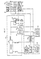
- Figure 1 is a block diagram of a data acquisition subsystem, including a circuit for acquiring and storing image data and alphanumeric identification data, in accordance with the present invention;
- Figure 2 is a block diagram illustrating the details of the data acquisition subsystem of Figure 1;
- Figure 3 is a right side elevational view depicting a sensitizing station, an exposure station, a toning station and a transfer station in accordance with the system of the present invention;
- Figure 4 is a perspective view of the sensitizing station of Figure 3;
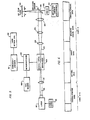
- Figure 5 is a right side elevational view depicting, partially in block format, the components of the exposure station of Figure 3 and their connection to a microprocessor and an embosser/ encoder;
- Figure 6 is an illustration of the format of the data on the magnetic tape which may be employed as the
semi-permanent storage 36 of Figure 1; - Figure 7 is a right side elevational view illustrating a
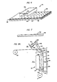
toner image 136 on theelectrophotographic film 66; - Figure 8A illustrates the relative positioning of a card and the toner image just prior to transfer of the toner image to the card;
- Figure 8B is a right side elevational view illustrating the platen in the transfer position, applying heat and pressure to the electrophotographic film to transfer the toner image to the card;
- Figure 8C is a right side elevational view illustrating the position of the platen after transfer of the toner image to the card;
- Figure 9 is a right side elevational view illustrating the peeling motion for peeling the electrophotographic film away from the card carrying the toner image; and
- Figure 10 is a right side elevational view of a station for overlaying a plastic protective layer over the image carried by the card.
- Figure 1 illustrates the data acquisition subsystem of the present invention. A
video camera 20 is employed to take a picture of a subject or cardholder 22 for whom a card 24 (Figure 3) is to be formed. In the preferred embodiment, the video camera is the RCA Model No. 2055 Vidicon camera which is a source of a live video picture. Thecard 24 which is to be generated for each cardholder 22 may be, for example, a plastic credit card, a driver's license, or any other type of identification card which is suitable for manufacture in the system of the present invention. For convenience, reference is made hereinafter to a "card" 24. - A
video digitizer 26 receives an analog image signal from thecamera 20 and generates a digital image signal, wherein each digital word represents a gray level of a small portion of the image. A graphics memory and refreshcontrol circuit 28 receives the digital image signal from thevideo digitizer 26 and generates an analog video signal for aCRT display 30 which displays an image of the subject 22. The graphics memory and refreshcontrol circuit 28 is also connected to a microprocessor andmemory circuit 32 for transmitting and receiving the digital data signal along a bi-directional data bus 33 and for receiving an address signal as well as input/output read and write signals. The microprocessor andmemory 32 may be connected to a remote computer or microprocessor via a standard RS-232C link. Akeyboard 34 is also connected to the microprocessor andmemory 32 so that alphanumeric data (e.g., embossing data, name and address information, account information, encoding information, and other identifying information) can be input to the microprocessor andmemory 32. This alphanumeric data is correlated with the corresponding digital image data and temporarily stored in the graphics memory and refreshcontrol circuit 28 and displayed onCRT display 30. The microprocessor andmemory 32 is also connected tosemi-permanent storage 36 so that the alphanumeric and digital image data which is temporarily stored in the graphics memory and refreshcontrol circuit 28 may be output to thesemi-permanent storage 36 for later retrieval. - The data acquisition subsystem of Figure 1 will be described in detail with reference to Figure 2. The microprocessor and
memory 32 controls the operation of the data acquisition subsystem and includes aprocessor 38, a PROM (programmable read only memory) 40, a RAM (random access memory) 42 and an input/output selection circuit 44. ThePROM 40 stores the control program for theprocessor 38. TheRAM 42 provides temporary storage for the digital picture data and alphanumeric data during transfer of data to thesemi-permanent storage 36. The I/O selection circuit 44 controls the input and output of data to and from the microprocessor andmemory 32. Thekeyboard 34 comprises analphanumeric refresh memory 46, aCRT controller 48, a character (dot)generator 50 and keyboard switches 52. When one of the keyboard switches 52 is depressed, thecentral processor 38 is interrupted and theprocessor 38 reads the ASCII character from thekeyboard 34 and stores it in theRAM 42. Thecharacter generator 50 decodes the keyboard character and sends a dot pattern, corresponding to the one of the keyboard switches 52 which has been depressed, to theCRT controller 48. This dot pattern is stored in thealphanumeric refresh memory 46 and theCRT display 30 continuously displays the dot pattern until thealphanumeric refresh memory 46 is altered or cleared. - The
video camera 20 andvideo digitizer 26 capture a live field of video from the camera within at least 1/30th of a second. In the preferred embodiment, thevideo digitizer 26 is a fully parallel (flash) analog-to-digital (A/D) converter. - The graphics memory and refresh
control circuit 28 includes acontrol timing circuit 54, apicture memory 56 and a digital-to-analog converter 58. Thecontrol timing circuit 54 samples the output of thevideo digitizer 26 at a rate which will yield a one-to-one aspect ratio. The sampled data is stored in thepicture memory 56 and is used to refresh theCRT display 30 which displays the picture. Thevideo camera 20 provides horizontal and vertical synchronization pulses for aligning the image displayed on theCRT display 30 with what the camera views. After the vertical retrace interval of thevideo camera 20, thecontrol timing circuit 54 initializes thepicture memory 56 to begin storing new camera data. After a picture has been completely stored in thepicture memory 56, the last digitized field of camera video is "frozen" in thepicture memory 56 and may then be accessed by the microprocessor andmemory 32 which receives the stored picture. The microprocessor andmemory 32 performs various processing routines to improve the quality of the image. In addition, the picture is compressed to reduce the amount of data necessary to represent the picture to be stored on thesemi-permanent storage 36. - The alphanumeric data which is input via the
keyboard 34 is correlated with the digital picture data received from thepicture memory 56 in theRAM 42. The correlated alphanumeric data and digital image data are temporarily stored in theRAM 42 and the digital words representing the image data are placed in specific memory locations representing the location of the picture element (pixel) whose gray level is the content of that memory element. Thus, the image is digitized so that the gray level in each discrete picture element is stored in memory locations representing the actual location in the visual image. The corresponding alphanumeric data is stored in adjacent memory locations to identify the images corresponding to the data. By using thekeyboard 34, it is also possible to superimpose alphanumeric data on the image on theCRT display 30. In this case, the image data which is stored will correspond to the combined image (picture plus alphanumeric data) which is generated on theCRT display 30. Thus, a convenient check on the correspondance between the alphanumeric data which is formed (e.g., embossed) on the card and the image which is formed on the card may be made. Once the correlated alphanumeric and digital image data have been stored in theRAM 42, thecentral processor 38 outputs the stored data on the bi-directional data bus 33 to thesemi-permanent storage 36. In the preferred embodiment, thesemi-permanent storage 36 includes a cassette interface and a magnetic tape cassette on which digital data is stored during the data acquisition phase of the present system. - Referring to Figure 6, the data stored on the magnetic tape for each card to be manufactured includes digital image (i.e. picture) data, print data, magnetic stripe data and emboss/encode data. The print data, emboss/encode data and magnetic stripe data are transmitted to an embosser/encoder 60 (Fig. 5). Thus, the system of the present invention may be operated "in line" with any automatic embossing system, and preferably with an automatic embossing system manufactured by Data Card Corporation. For example, the system of the present invention may be operated "in line" with the Data Card Series 4000 embosser/encoder described in U.S. Patent 4,088,216, assigned to the assignee of the present application, or the Data Card Series 1500 embosser described in U.S. Patent Re 27,809, assigned to the assignee of the present application. Alternatively, the system of the present invention may be used as a stand-alone system to fully image a card with alphanumeric data, picture(s), signature(s) and the like.
- Figure 3 is a right side elevational view of the overall image generating and transfer subsystem of the present invention. A
supply roll 64 holds a roll supply of an electrophotographic medium 66 which in the preferred embodiment is electrophotographic film. In an alternative embodiment a selenium drum is employed as theelectrophotographic medium 66. Theelectrophotographic film 66 is drawn around aroller 68 and past a sensitizing station comprising acorona generator 70 for placing a charge on the surface of theelectrophotographic film 66. The sensitizedfilm 66 is transported past anexposure station 72 and a toningstation 74. Theexposure station 72 generates a modulated laser beam which is scanned across the sensitizedelectrophotographic film 66. As thefilm 66 is transported past the toningstation 74, charged toner is attracted to the scanned portions of thefilm 66, so that a toner image is formed on thefilm 66. Thefilm 66, carrying the toner image, is transported around a pair ofrollers film 66 so that anair knife 80 can remove any loose toner particles and residual solvent which are carried by thefilm 66. Thefilm 66 is transported around aroller 62 which is spring biased by aspring 64 to form a buffer loop, which provides a flexible film interface between the image development portion of the system, which operates at substantially constant film velocity, and the image transfer portion of the system which operates with incremental motion. A pair ofrollers image carrying film 66 in atransfer station 90. Thetransfer station 90 comprises a card back upblock 92 and aheated platen 94. After the film is transported through thetransfer station 90 and the toner image is transferred from thefilm 66 to thecard 24, thefilm 66 is transported to a take uproll 96 where it is stored for disposal. - Referring to Figure 4, the
electrophotographic film 66 and the sensitizing station will be described. As noted above, in the preferred embodiment, theelectrophotographic medium 66 compriseselectrophotographic film 66. Theelectrophotographic film 66 comprises a support base 98, a thinconductive layer 100 which is grounded to the film spool (not shown) and aphotoconductive layer 102 which has a high dark resistance. Thecorona generator 70 comprises athin wire 104 and a conductingenclosure 106. Thefilm 66 is sensitized (i.e., made light sensitive) by generating a voltage of 3,500 volts or more between thewire 104 and theenclosure 106. This high voltage causes the surrounding air to ionize, thereby causing positive ions to be attracted to thephotoconductive layer 102 of thefilm 66. Thecorona generator 70 is employed to place a uniform electrostatic charge on the surface of thefilm 66. - Referring to Figure 5, the
exposure station 72 of Figure 3 will be described. Theexposure station 72 may be directly connected to the data acquisition subsystem illustrated in Figure 1. Alternatively, digital image data are alphanumeric data can be stored on magnetic tape at a remote location (using the data acquisition subsystem of Figure 1) and the magnetic tape can then be transported to a location for manufacturing a plurality ofcards 24. In the preferred embodiment, the data acquisition subsystem of Figure 1 is employed at remoate locations to store digital image data and alphanumeric data for a plurality of subjects 22. The stored digital image data and alphanumeric data is then transported (e.g., either physically, as a magnetic tape or disk, or over phone lines) to a site having complete facilities for manufacturing cards (including, e.g., an embosser/encoder, a card attaching system, etc.) where the information stored on the magnetic tape is read by a tape reader 108. Thus, the tape reader 108. provides both alphanumeric data and digital image data to amicroprocessor 110 which in turn provides the alphanumeric data to the embosser/encoder 60 and supplies the digital image data to theexposure station 72. In the embodiment of the present invention in which the data acquisition subsystem of Figure 1 is used to read the magnetic tape during the card forming process, themicroprocessor 110 and tape read 108 are not required since the microprocessor andmemory 32 and thesemi-permanent storage 36 perform these functions. - The
exposure station 72 comprises alaser 112, powered by itsown power supply 114, for generating a coherent light beam 116, hereinafter referred to as laser beam 116. In the preferred embodiment thelaser 112 is a Hughes model 3225 H-PC 5MW HeNe laser. Abeam compressor lens 118 compresses the laser beam 116 and feeds the laser beam 116 to an acousto-optic modulator 120. The acousto-optic modulator 120 is connected to themicroprocessor 110 to receive the digital image data. The acousto-optic modulator 120 digitally modulates the laser beam 116, in accordance with the digital image data, to generate a modulatedlaser beam 122 which is passed through a pair ofbeam expander lenses objective lens 128. Thebeam expander lenses laser beam 122 to achieve smaller spot sizes at the plane of thefilm 66. The modulatedlaser beam 122 passes from theobjective lens 128 to adeflection mirror 130 which is oscillated by agalvanometer 132 under the control ofdeflection control electronics 134. Thus, the modulatedlaser beam 122 is scanned back and forth across the plane of thefilm 66 in the direction of the arrows A and B in Figure 5. - In the preferred embodiment, the acousto-
optic modulator 120 comprises an isomet 1205C or 1206C acousto-optic modulator; thegalvanometer 132 comprises a General Scanning S-230-08 galvanometer; and thedeflection control electronics 134 comprises a General Scanning Model AX-700 galvanometer controller. - By scanning the modulated
laser beam 122 across the sensitizedelectrophotographic film 66, the impingement of thelaser beam 122 upon thephotoconductive layer 102 causes the positive ions which are attracted to the surface of thephotoconductive layer 102 to be conducted to the thinconductive layer 100. Thus, a latent electrostatic image is formed on the surface of thephotoconductive layer 102. This image has a resolution of 125 pixels per inch and requires an exposure time of 1/60th second. The image is broken down into 2,425 pixels per square cm, each pixel being .02 cm2 with 64 possible dot positions. A varying gray scale is achieved by selectively exposing the dot positions within each pixel. - In the preferred embodiment, the
electrophotographic film 66 is Kodak SO-112 electrophotographic film and the toner which is used to tone the film is Kodak MX-1112 or MX-1125 liquid toner. As theelectrophotographic film 66 is transported past the toningstation 74, the toner (which is positively charged in the preferred embodiment) is attracted to the areas of thephotoconductive layer 102 which have been exposed by the modulatedlaser beam 122. Thus, a toner image 136 (Figure 7) is formed on the surface of theelectrophotographic film 66. - Referring to Figures 8A-8C and 9, the transfer of the
toner image 136 to thecard 24 at thetransfer station 90 will be described. Theheated platen 94 includes acontact area 138 having dimensions which are substantially the same as thetoner image 136 which is to be transferred to thecard 24. This contact area 138 (and hence the image 136) may be any desired size and, for example, may be of a size to occupy the upper right hand corner of thecard 24. The card back upblock 92 is fixed to asupport 140 and includes upper and lower card guides 142 and 144, respectively, for confining the position of thecard 24 against the surface of the card back upblock 92. Drivenrollers 146 are employed to transport thecard 24 into an image transfer position on the card back upblock 92 and avacuum conduit 148 is selectively actuated to hold the card in position against the card back upblock 92. Once thecard 24 has been transported into an image receiving position by the drivenrollers 146 and thefilm 66 carrying thetoner image 136 has been transported into a position for transfer, theheated platen 94 is moved in the direction of arrow C in Figure 8A so that thecontact area 138 of theheated platen 94 presses the support base 98 of theelectrophotographic film 66, thereby pressing thetoner image 136 against the card 24 (Figure 8B). Theheated platen 94 dwells at this contact position for a predetermined period of time and is then withdrawn in the direction of arrow D in Figure 8B. - In order to achieve the desired transfer of the
toner image 136 to thecard 24, it is necessary to hold thecard 24 flat while the electrophotographic film is pulled away in a peeling motion. The peeling motion creates a very high stress at the interface of the peeled material (i.e., the electrophotographic film 66) with the toner. Since the toner is fused by the heat and pressure generated by thecontact area 138 of theplaten 94, and because of the elastic properties of the fused toner, the stress diminishes through the toner layer to thecard 24. Thus, any break or separation will occur at the point of the highest stress, which is the point at which theelectrophotographic film 66 and thetoner image 136 interface. - As best seen in Figure 8A, the
transfer station 90 is adapted to peel theelectrophotographic film 66 from thecard 24 andtoner image 136. When theheated platen 94 is in the position illustrated in Figure 8B theelectrophotographic film 66 follows a path denoted by the dashed line F in Figure 8A. Theroller 88 is connected to alink 150 which pivots about apivot point 152. Theroller 88 is biased to the position illustrated by the solid lines in Figure 8A by abias spring 154 which is connected to asupport 155 and to anend 156 of thelink 150. Once theheated platen 94 has been retracted from its transfer position, thelink 150 is pivoted about pivot point 152 (by e.g. a solenoid 158) so that thelink 150 androller 88 are moved to the position illustrated by the dashed lines in Figure 8A. At this point, the path of theelectrophotographic film 66 is illustrated by the dotted line G in Figure 8A, so that as theelectrophotographic film 66 is transported aroundroller 88 the peeling motion illustrated in Figure 9 is generated, thereby peeling theelectrophotographic film 66 from thetoner image 136 which remains fused to thecard 24. After the peeling process is completed, thesolenoid 158 is deenergized, thelink 150 pivots back to the position illustrated by the solid lines in Figure 8A under the bias of thespring 154 and thetoner image 136 remains on thecard 24 as illustrated in Figure 8C. - The particular heat, pressure and dwell time employed in the transfer process illustrated in Figures 8A to 8C will vary in accordance with the requirements of a particular application. Thus, it is only necessary that the heat, pressure and dwell time be sufficient to fuse the toner to the surface of the
card 24. In order to determine one possible set of ranges for heat, pressure and dwell time, which produce an acceptable transfer of thetoner image 136 to the outside surface of thecard 24, tests using a .076 cm thick laminated polyvinyl chloride card were made. The image dimensions were 2.2 cm by 1.75 cm. - The pressure of the
platen 94 against thecard 24 was varied from 620 to 3858 kPa, while holding the platen temperature and dwell time constant at 204°C and 400 ms, respectively. - The acceptable pressure range was determined to be from 2480 to 3858 kPa. Decreasing the platen pressure caused a greater sensitivity to the platen squareness and thickness, thereby causing partial image drop outs (i.e., partial non-transfer) as well as greater sensitivity to partial image drop outs or flaws due to dust particles. Increasing the platen pressure caused plastic card deformation behind the area where the
card 24 contacted thetoner image 136. - The temperature of the
platen 94 was varied from 130 to 271°C while maintaining the platen pressure and dwell time constant at 3858 kPa and 400 ms, respectively. - The acceptable temperature range was determined to be from 182 to 213°C. The low temperature range of from 130 to 154°C produced nonuniform, poor transfer characteristics. The acceptable temperature range of 182 to 213°C produced excellent transfer characteristics and little mechanical distortion of the card. The high temperature range of 213 to 271°C caused severe card distortion and some transfer of the film dye, giving the image formed on the card 24 a blue hue. At 271°C the
photoconductive layer 102 separated from theelectrophotographic film 66. - The dwell time of the
platen 94 was varied from 50 ms to 1 second while maintaining the platen pressure and temperature constant at 3445 kPa and 204°C, respectively. - The acceptable range for the dwell time was determined to be from 50 ms to 600 ms. This dwell time produced excellent image transfer, however, card distortion behind the image area increased from insignificant at a 50 ms dwell to severe at a 600 ms dwell. However, the card distortion up to 600 ms is acceptable. Dwell times greater than 600 ms produced separation and transfer of the
photoconductive layer 102 to thecard 24. - The
heated transfer platen 94 of the present invention provides significant advantages over prior art image transfer devices such as heated rollers. In the present invention, no visible heat marks remain on the card in areas other than the image area, so that the surface finish of the remaining portions of thecard 24 remains intact. In addition, thecard 24 may be embossed and/or encoded prior to image transfer since theplaten 94 presses only on those portions of thecard 24 which are to receive theimage 136. Thus, theplaten 94 will not damage any prior embossing, nor will it damage any sensitive surfaces such as magnetic stripes which are frequently placed on the back of thecard 24. - While the
toner image 136 which is transferred to thecard 24 is stable and durable, in the preferred embodiment a protective layer is placed over theimage 136 in order to make the image more able to withstand the abrasion and chemicals present in the wallet environment. Referring to Figure 10, a protectivelayer transfer station 158 which is similar to thetransfer station 90 is illustrated. Acarrier film 160 carries a plurality of thinthermoplastic coatings 162 which are approximately the same size as thetoner image 136 which is transferred to thecard 24. The path of thecarrier film 160 is defined byrollers heated platen 170 includes acontact area 172 for contacting thecarrier film 160 on the side opposite thethermoplastic coating 162. A card back upblock 174 is mounted on asupport 176 and includes upper and lower card guides 178 and 180, respectively. Avacuum conduit 182 provides a selectively actuated source of vacuum for maintaining thecard 24 against the card back upblock 174. Drivenrollers 184 are driven to transport thecard 24 into and out of the protectivelayer transfer station 158. Theheated platen 170 is actuated in the same manner as theheated platen 94 in thetransfer station 90. Similarly, theroller 166 is connected to alink 186 which is pivoted about pivot point 188 by asolenoid 190, so that thecarrier film 160 is peeled from thethermoplastic coating 162 in the same manner in which theelectrophotographic film 66 is peeled from thecard 24. In the preferred embodiment, thethermoplastic coating 162 is 381 millionths of a cm thick and thecarrier film 160 is .005 cm thick. To produce an acceptable thermoplastic film transfer to thecard 24, a preferred minimum pressure of 1100 kPa and a platen temperature of from 160 to 216°C is applied. - The operation of the system will now be described with reference to Figures 2, 3 and 5.
- In general, it is desirable to store digital image data and corresponding alphanumeric data for plural cardholders on a magnetic tape, so that a large number of
cards 24 may be produced at a single time by inputting the data into a card forming and processing system. In order to capture and store the images as digital image data and to store the alphanumeric data, thevideo camera 20 takes a picture of each cardholder 22, and the picture is then digitized by thevideo digitizer circuit 26 and sent to the graphics memory and refreshcontrol circuit 28. The image which is captured by thecamera 20 is displayed on theCRT display 30 and the digital image data is transferred from the graphics memory and refreshcontrol circuit 28 to the microprocessor andmemory 32. Similarly, alphanumeric data is input to the microprocessor andmemory 32 via thekeyboard 34. The alphanumeric data may also be displayed on the CRT display. When an operator views the desired image on theCRT display 30 and the desired alphanumeric data has been input from thekeyboard 34, the corresponding digital image data and alphanumeric data are stored in the microprocessor andmemory 32 and are then transferred to thesemi-permanent storage 36. As noted above, it is preferred to store the alphanumeric data and digital image data for a large number of cardholders 22 on thesemi-permanent storage 36. - When it is desired to process (i.e., emboss/ encode a card, form an image on the card, print on a card carrier, and attach a corresponding
card 24 to a card carrier) acard 24, the tape reader 108 reads the alphanumeric data and digitial image data from the semi-permanent storage 36 (e.g., magnetic tape) and transmits this data to themicroprocessor 110. Themicroprocessor 110 sends the alphanumeric data to the embosser/encoder 60 and the digital image data to the acousto-optic modulator 120 which is a part of theexposure station 72. Theelectrophotographic film 66 is transported past the sensitizingstation 70 where theelectrophotographic film 66 is uniformly charged. The chargedelectrophotographic film 66 is transported past theexposure station 72 where the modulated laser beam 122 (modulated in accordance with the digital image data) is scanned across the chargedelectrophotographic film 66 by thedeflection mirror 130, so as to .selectively discharge portions of theelectrophotographic film 66 in accordance with the digital image data received by the acousto-optic modulator 120. Thus, once theelectrophotographic film 66 has been scanned by the modulatedlaser beam 122, thefilm 66 carries a latent electrostatic image. The selectively dischargedelectrophotographic film 66 is transported past a toningstation 74 where charged toner is attracted to the discharged portions of theelectrophotographic film 66, so that the toner image 136 (Fig. 7) is formed on theelectrophotographic film 66. Theelectrophotographic film 66 is transported past theair knife 80 so as to remove any loose toner from thetoner image 136, and is subsequently transported to a position in between theheated platen 94 and thecard 24 which is supported by the card back-upblock 92. Thecard 24 has been embossed and/or encoded by the embosser/encoder 60 in accordance with the alphanumeric data corresponding to the toner image which is to be transferred to thecard 24. Thetoner image 136 is pressed against thecard 24 by the platen 94 (Figures 8A-8C) to transfer thetoner image 136 to thecard 24. As illustrated in Figure 9, theelectrophotographic film 66 is peeled away from thecard 24 so that thetoner image 136 remains intact on thecard 24. Thecard 24 carrying thetoner image 136 is then transported to the protectivelayer transfer station 158 where thethermoplastic coating 162 is transferred to thecard 24 to protect thetoner image 136 from degradation due to the abrasion and chemicals in a wallet environment. After thethermoplastic coating 162 has been overlayed on thecard 24, the card 24 (carrying the image and embossing/encoding) may be transported to thecard attaching system 62 where the card is attached to a carrier having corresponding cardholder indicia printed thereon. - The system of the present invention may be implemented in numerous ways. For example, any type of electrophotographic medium, such as a selenium drum, may be used as the
electrophotographic medium 66. Similarly, the electrophotographic medium 66 may be charged or discharged in any desired manner, with the corresponding charged toner (i.e. positive or negative) being used to tone the charged or discharged areas. In addition, thecard 24 may be embossed and/or encoded before or after the image is formed on the card; and, if desired, embossing or encoding can be omitted if the image includes the alphanumeric data as a part thereof. The values of heat, pressure and dwell time employed to transfer thetoner image 136 to the surface of thecard 24 may be varied in accordance with the requirements of a particular application. Further, although the card used in the above experiments was composed of polyvinyl chloride, thecard 24 may be made of any suitable material to which the toner can be fused. - Since numerous modifications and changes will readily occur to those skilled in the art, it is not desired to limit the invention to the exact construction and operation shown and described, and accordingly all suitable modifications and equivalents may be resorted to, falling within the scope of the claims.
Claims (22)
Priority Applications (1)
| Application Number | Priority Date | Filing Date | Title |
|---|---|---|---|
| AT83901873T ATE46394T1 (en) | 1982-05-07 | 1983-05-03 | METHOD OF MAKING AN IMAGE ON THE SURFACE OF A PLASTIC CARD. |
Applications Claiming Priority (2)
| Application Number | Priority Date | Filing Date | Title |
|---|---|---|---|
| US376031 | 1982-05-07 | ||
| US06/376,031 US4467335A (en) | 1982-05-07 | 1982-05-07 | System for forming an image on the surface of a plastic card |
Publications (3)
| Publication Number | Publication Date |
|---|---|
| EP0107722A1 EP0107722A1 (en) | 1984-05-09 |
| EP0107722A4 EP0107722A4 (en) | 1986-06-05 |
| EP0107722B1 true EP0107722B1 (en) | 1989-09-13 |
Family
ID=23483408
Family Applications (1)
| Application Number | Title | Priority Date | Filing Date |
|---|---|---|---|
| EP83901873A Expired EP0107722B1 (en) | 1982-05-07 | 1983-05-03 | System for forming an image on the surface of a plastic card |
Country Status (6)
| Country | Link |
|---|---|
| US (1) | US4467335A (en) |
| EP (1) | EP0107722B1 (en) |
| AU (1) | AU568592B2 (en) |
| DE (2) | DE3380570D1 (en) |
| PH (1) | PH17657A (en) |
| WO (1) | WO1983004092A1 (en) |
Cited By (1)
| Publication number | Priority date | Publication date | Assignee | Title |
|---|---|---|---|---|
| DE10030739A1 (en) * | 2000-06-23 | 2002-01-17 | Oce Printing Systems Gmbh | Device and method for a printing and / or copying device with reduced thermal stress on the carrier material |
Families Citing this family (24)
| Publication number | Priority date | Publication date | Assignee | Title |
|---|---|---|---|---|
| AU2841784A (en) * | 1983-05-18 | 1984-11-22 | Australian Electro Optics Pty. Limited | Laser beam marking |
| US4629306A (en) * | 1983-07-22 | 1986-12-16 | Data Card Corporation | System for forming picture and alphanumeric images on the surface of a plastic card |
| US4675746A (en) * | 1983-07-22 | 1987-06-23 | Data Card Corporation | System for forming picture, alphanumeric and micrographic images on the surface of a plastic card |
| JPH0614672B2 (en) * | 1983-11-22 | 1994-02-23 | 株式会社リコー | Image forming device |
| IT1184408B (en) * | 1985-04-09 | 1987-10-28 | Telettra Lab Telefon | Forming printed circuit boards |
| US5161233A (en) * | 1988-05-17 | 1992-11-03 | Dai Nippon Printing Co., Ltd. | Method for recording and reproducing information, apparatus therefor and recording medium |
| US5037216A (en) * | 1988-09-23 | 1991-08-06 | Datacard Corporation | System and method for producing data bearing cards |
| US5025399A (en) * | 1988-09-23 | 1991-06-18 | Datacard Corporation | Method and apparatus for personalizing plastic cards |
| DE3934565A1 (en) * | 1989-07-04 | 1991-04-18 | Microbox Dr Welp Gmbh & Co | CAD MICROFILM LASER PLOTTER |
| US5171039A (en) * | 1990-08-27 | 1992-12-15 | Micro Innovations, Incorporated | Medical information card |
| US5157424A (en) * | 1990-09-14 | 1992-10-20 | Nbs Imaging Systems, Inc. | Method and apparatus for manufacturing tamper-resistant identification cards |
| FR2667416B1 (en) * | 1990-09-28 | 1995-02-03 | Dassault Electronique | PLANT FOR PROCESSING A TITLE, PARTICULARLY A TRANSPORT TITLE, CORRESPONDING METHOD AND TITLE. |
| US5249828A (en) * | 1991-09-18 | 1993-10-05 | Axelrod Herbert R | Printed product and method of manufacture |
| JPH05207442A (en) * | 1992-01-30 | 1993-08-13 | Matsushita Electric Ind Co Ltd | Coder for animation signal |
| EP0569171A1 (en) * | 1992-05-08 | 1993-11-10 | Moore Business Forms, Inc. | Method and apparatus for printing photographs on documents |
| GB2281535A (en) * | 1993-08-16 | 1995-03-08 | Image Database Technologies | A method of producing a personal information-bearing card |
| AU683095B2 (en) * | 1993-12-27 | 1997-10-30 | Kabushiki Kaisha Ace Denken | Image displaying game machine and image display controlling method |
| US5671271A (en) * | 1995-05-25 | 1997-09-23 | Henderson; Daniel A. | Dialer programming system and device with integrated printing process |
| US6086707A (en) * | 1996-02-29 | 2000-07-11 | Raytheon Company | Method for making an identification document |
| FR2758197A1 (en) * | 1996-10-17 | 1998-07-10 | Gkard Sas | METHOD AND INSTALLATION FOR REALIZING AN INFALSIFIABLE PERSONALIZED USER TITLE |
| US6375081B1 (en) | 1999-02-02 | 2002-04-23 | The Standard Register Company | Business form including smart card and smart card reader |
| US6221545B1 (en) | 1999-09-09 | 2001-04-24 | Imation Corp. | Adhesives for preparing a multilayer laminate featuring an ink-bearing surface bonded to a second surface |
| JP4300792B2 (en) * | 2002-12-06 | 2009-07-22 | 富士ゼロックス株式会社 | Plastic sheet manufacturing method, manufacturing apparatus thereof, and collating apparatus |
| US8077192B2 (en) * | 2008-01-07 | 2011-12-13 | Zink Imaging, Inc. | Platen temperature model |
Family Cites Families (26)
| Publication number | Priority date | Publication date | Assignee | Title |
|---|---|---|---|---|
| US314929A (en) * | 1885-03-31 | Oil or gas stove | ||
| US3343142A (en) * | 1963-01-02 | 1967-09-19 | Xerox Corp | Xerographic coding and information storage on a specular business machine card |
| US3389403A (en) * | 1966-09-06 | 1968-06-18 | Dresser Ind | Laser beam recorder with means to compensate for change in angular velocity of swept beam |
| US3685896A (en) * | 1966-11-21 | 1972-08-22 | Xerox Corp | Duplicating method and apparatus |
| US3497411A (en) * | 1968-03-14 | 1970-02-24 | Ibm | Method and materials for printing smooth magnetic layers |
| US3582439A (en) * | 1968-04-01 | 1971-06-01 | Polaroid Corp | Id card laminar structure and processes of making same |
| US3597071A (en) * | 1968-08-30 | 1971-08-03 | Xerox Corp | Diverse-input system for electrostatically reproducing and recording information |
| JPS4843819B1 (en) * | 1970-12-28 | 1973-12-20 | ||
| FR2127373A5 (en) * | 1971-03-05 | 1972-10-13 | Thomson Csf | |
| US4052739A (en) * | 1972-05-19 | 1977-10-04 | Matsushita Electric Industrial Co., Ltd. | Electronic engraving system |
| JPS5335729B2 (en) * | 1972-05-23 | 1978-09-28 | ||
| US3922485A (en) * | 1972-11-27 | 1975-11-25 | Xerox Corp | Flying spot scanner with scan detection |
| US4060441A (en) * | 1973-04-20 | 1977-11-29 | Kabushiki Kaisha Ricoh | Method for forming a transparent protective coating on a photograph or the like |
| US4006986A (en) * | 1973-08-17 | 1977-02-08 | Coulter Information Systems, Inc. | Image recording apparatus for electrophotographic film |
| JPS50105000A (en) * | 1974-01-24 | 1975-08-19 | ||
| GB1477203A (en) * | 1974-02-11 | 1977-06-22 | Whiley Ltd G | Manufacture of image-bearing cards and other documents |
| GB1520281A (en) * | 1974-07-10 | 1978-08-02 | Canon Kk | Electrophotographic recording apparatus |
| US4002829A (en) * | 1974-08-29 | 1977-01-11 | W. R. Grace & Co. | Autosynchronous optical scanning and recording laser system with fiber optic light detection |
| US4130834A (en) * | 1974-12-20 | 1978-12-19 | Videoprint Gesellschaft Fur Industrie-Fernsehen Mbh | Method of and apparatus for the production of photographic stills |
| US3974506A (en) * | 1974-12-30 | 1976-08-10 | Xerox Corporation | Scanning system for imaging characters combined with graphic curves |
| US4175851A (en) * | 1975-02-03 | 1979-11-27 | Canon Kabushiki Kaisha | Recording position adjuster |
| US4052715A (en) * | 1976-02-25 | 1977-10-04 | Xerox Corporation | Digital half-tone grey scale expansion system |
| US4169275A (en) * | 1977-03-10 | 1979-09-25 | Xerox Corporation | Reproduction scanning system having intermediate storage between input and output scanning stations |
| NL7802146A (en) * | 1977-03-10 | 1978-09-12 | Xerox Corp | REPRODUCTION SCANNING SYSTEM EQUIPPED WITH AN INTERMEDIATE MEMORY BETWEEN THE IMPORT AND EXPORT REMOTE STATIONS. |
| DE2750612C3 (en) * | 1977-11-11 | 1980-11-27 | Siemens Ag, 1000 Berlin Und 8000 Muenchen | Device for transferring a toner image from a circumferential, belt-shaped image carrier to an image receiving material |
| GB2101931A (en) * | 1981-05-20 | 1983-01-26 | Harrison And Sons | Making a security card |
-
1982
- 1982-05-07 US US06/376,031 patent/US4467335A/en not_active Expired - Fee Related
- 1982-12-07 PH PH28235A patent/PH17657A/en unknown
-
1983
- 1983-05-03 EP EP83901873A patent/EP0107722B1/en not_active Expired
- 1983-05-03 DE DE8383901873T patent/DE3380570D1/en not_active Expired
- 1983-05-03 AU AU16093/83A patent/AU568592B2/en not_active Ceased
- 1983-05-03 DE DE19833344164 patent/DE3344164T1/en not_active Ceased
- 1983-05-03 WO PCT/US1983/000629 patent/WO1983004092A1/en not_active Ceased
Cited By (1)
| Publication number | Priority date | Publication date | Assignee | Title |
|---|---|---|---|---|
| DE10030739A1 (en) * | 2000-06-23 | 2002-01-17 | Oce Printing Systems Gmbh | Device and method for a printing and / or copying device with reduced thermal stress on the carrier material |
Also Published As
| Publication number | Publication date |
|---|---|
| EP0107722A4 (en) | 1986-06-05 |
| US4467335A (en) | 1984-08-21 |
| EP0107722A1 (en) | 1984-05-09 |
| DE3344164T1 (en) | 1984-10-31 |
| PH17657A (en) | 1984-10-25 |
| AU1609383A (en) | 1983-12-02 |
| AU568592B2 (en) | 1988-01-07 |
| DE3380570D1 (en) | 1989-10-19 |
| WO1983004092A1 (en) | 1983-11-24 |
Similar Documents
| Publication | Publication Date | Title |
|---|---|---|
| US4467335A (en) | System for forming an image on the surface of a plastic card | |
| US4675746A (en) | System for forming picture, alphanumeric and micrographic images on the surface of a plastic card | |
| US2990278A (en) | Method and apparatus for transferring and fixing xerographic images | |
| US2741960A (en) | Record controlled printer | |
| CA1339151C (en) | Method for recording and reproducing information, apparatus therefor andrecording medium | |
| US3250636A (en) | Method and apparatus for image reproduction with the use of a reusable heat demagnetizable ferromagnetic imaging layer | |
| US3430254A (en) | Tesi printing with flexible electrode on endless belt | |
| GB1577098A (en) | Method and apparatus for xerographically printing a composite record of fixed and variable data | |
| US3615389A (en) | Direct image transfer to thermoplastic tape | |
| EP0414454B1 (en) | Copy quality monitoring | |
| US2510200A (en) | Facsimile system with selected area scanning | |
| EP0394142A3 (en) | Electrophotographic photosensitive member | |
| US3934256A (en) | Identification card producing apparatus | |
| US3321308A (en) | Xerographic induction recording | |
| US5185619A (en) | Electrostatic printing method and apparatus employing a pyroelectric imaging member | |
| US3343142A (en) | Xerographic coding and information storage on a specular business machine card | |
| US4629306A (en) | System for forming picture and alphanumeric images on the surface of a plastic card | |
| US3418119A (en) | Method of cumulatively recording intelligence on a record card | |
| US2826634A (en) | Method and means for magnetic reproduction of pictures | |
| US3442645A (en) | Electrophotographic method | |
| EP0747787B1 (en) | Tool for high temperature roll nip measurements | |
| US3047871A (en) | Electronic printer | |
| US3406405A (en) | Thermal modulation thermoplastic recording | |
| US6043830A (en) | Apparatus for pattern generation on a dielectric substrate | |
| US4515879A (en) | Optical mass memory system using electrophotography |
Legal Events
| Date | Code | Title | Description |
|---|---|---|---|
| PUAI | Public reference made under article 153(3) epc to a published international application that has entered the european phase |
Free format text: ORIGINAL CODE: 0009012 |
|
| AK | Designated contracting states |
Designated state(s): AT BE CH DE FR GB LI LU NL SE |
|
| 17P | Request for examination filed |
Effective date: 19840511 |
|
| A4 | Supplementary search report drawn up and despatched |
Effective date: 19860605 |
|
| 17Q | First examination report despatched |
Effective date: 19880212 |
|
| GRAA | (expected) grant |
Free format text: ORIGINAL CODE: 0009210 |
|
| AK | Designated contracting states |
Kind code of ref document: B1 Designated state(s): AT BE CH DE FR GB LI LU NL SE |
|
| PG25 | Lapsed in a contracting state [announced via postgrant information from national office to epo] |
Ref country code: SE Effective date: 19890913 Ref country code: NL Effective date: 19890913 Ref country code: BE Effective date: 19890913 Ref country code: AT Effective date: 19890913 |
|
| REF | Corresponds to: |
Ref document number: 46394 Country of ref document: AT Date of ref document: 19890915 Kind code of ref document: T |
|
| REF | Corresponds to: |
Ref document number: 3380570 Country of ref document: DE Date of ref document: 19891019 |
|
| ET | Fr: translation filed | ||
| REG | Reference to a national code |
Ref country code: CH Ref legal event code: PL |
|
| NLV1 | Nl: lapsed or annulled due to failure to fulfill the requirements of art. 29p and 29m of the patents act | ||
| PGFP | Annual fee paid to national office [announced via postgrant information from national office to epo] |
Ref country code: FR Payment date: 19900418 Year of fee payment: 8 |
|
| PGFP | Annual fee paid to national office [announced via postgrant information from national office to epo] |
Ref country code: DE Payment date: 19900420 Year of fee payment: 8 |
|
| PGFP | Annual fee paid to national office [announced via postgrant information from national office to epo] |
Ref country code: GB Payment date: 19900427 Year of fee payment: 8 |
|
| PG25 | Lapsed in a contracting state [announced via postgrant information from national office to epo] |
Ref country code: LU Free format text: LAPSE BECAUSE OF NON-PAYMENT OF DUE FEES Effective date: 19900531 Ref country code: LI Free format text: LAPSE BECAUSE OF NON-PAYMENT OF DUE FEES Effective date: 19900531 Ref country code: CH Free format text: LAPSE BECAUSE OF NON-PAYMENT OF DUE FEES Effective date: 19900531 |
|
| PLBI | Opposition filed |
Free format text: ORIGINAL CODE: 0009260 |
|
| 26 | Opposition filed |
Opponent name: GAO GESELLSCHAFT FUER AUTOMATION UND ORGANISATION Effective date: 19900612 |
|
| RDAG | Patent revoked |
Free format text: ORIGINAL CODE: 0009271 |
|
| STAA | Information on the status of an ep patent application or granted ep patent |
Free format text: STATUS: PATENT REVOKED |
|
| REG | Reference to a national code |
Ref country code: CH Ref legal event code: PL |
|
| 27W | Patent revoked |
Effective date: 19910415 |
|
| GBPR | Gb: patent revoked under art. 102 of the ep convention designating the uk as contracting state |