EP0107705B1 - Process for producing a slurry containing concentrated liquid and ice crystals and subassembly therefor - Google Patents
Process for producing a slurry containing concentrated liquid and ice crystals and subassembly therefor Download PDFInfo
- Publication number
- EP0107705B1 EP0107705B1 EP83901679A EP83901679A EP0107705B1 EP 0107705 B1 EP0107705 B1 EP 0107705B1 EP 83901679 A EP83901679 A EP 83901679A EP 83901679 A EP83901679 A EP 83901679A EP 0107705 B1 EP0107705 B1 EP 0107705B1
- Authority
- EP
- European Patent Office
- Prior art keywords
- slurry
- crystallizer
- reservoir
- tubes
- scraper
- Prior art date
- Legal status (The legal status is an assumption and is not a legal conclusion. Google has not performed a legal analysis and makes no representation as to the accuracy of the status listed.)
- Expired
Links
- 239000002002 slurry Substances 0.000 title claims abstract description 87
- 239000013078 crystal Substances 0.000 title claims abstract description 31
- 238000000034 method Methods 0.000 title claims description 17
- 230000008569 process Effects 0.000 title claims description 13
- 239000007788 liquid Substances 0.000 title claims description 7
- 238000012546 transfer Methods 0.000 claims abstract description 22
- 239000003507 refrigerant Substances 0.000 claims description 12
- 239000012452 mother liquor Substances 0.000 claims description 9
- 239000000126 substance Substances 0.000 claims description 6
- 230000008014 freezing Effects 0.000 claims description 5
- 238000007710 freezing Methods 0.000 claims description 5
- 239000000243 solution Substances 0.000 claims description 5
- XLYOFNOQVPJJNP-UHFFFAOYSA-N water Substances O XLYOFNOQVPJJNP-UHFFFAOYSA-N 0.000 claims description 5
- 239000012267 brine Substances 0.000 claims 1
- 239000013535 sea water Substances 0.000 claims 1
- HPALAKNZSZLMCH-UHFFFAOYSA-M sodium;chloride;hydrate Chemical compound O.[Na+].[Cl-] HPALAKNZSZLMCH-UHFFFAOYSA-M 0.000 claims 1
- 239000012530 fluid Substances 0.000 abstract description 5
- 238000002425 crystallisation Methods 0.000 abstract description 4
- 230000008025 crystallization Effects 0.000 abstract description 4
- 239000000047 product Substances 0.000 description 4
- 238000007790 scraping Methods 0.000 description 4
- 238000004140 cleaning Methods 0.000 description 3
- 230000008020 evaporation Effects 0.000 description 3
- 238000001704 evaporation Methods 0.000 description 3
- 239000012527 feed solution Substances 0.000 description 3
- 239000008187 granular material Substances 0.000 description 3
- 230000003247 decreasing effect Effects 0.000 description 2
- 239000004677 Nylon Substances 0.000 description 1
- 230000015572 biosynthetic process Effects 0.000 description 1
- 238000006243 chemical reaction Methods 0.000 description 1
- 239000012141 concentrate Substances 0.000 description 1
- 238000010276 construction Methods 0.000 description 1
- 230000002939 deleterious effect Effects 0.000 description 1
- 238000011033 desalting Methods 0.000 description 1
- 238000013461 design Methods 0.000 description 1
- 230000006866 deterioration Effects 0.000 description 1
- 238000006073 displacement reaction Methods 0.000 description 1
- 238000010438 heat treatment Methods 0.000 description 1
- 238000004519 manufacturing process Methods 0.000 description 1
- 238000012986 modification Methods 0.000 description 1
- 230000004048 modification Effects 0.000 description 1
- 229920001778 nylon Polymers 0.000 description 1
- 230000008520 organization Effects 0.000 description 1
- 239000002245 particle Substances 0.000 description 1
- 239000006223 plastic coating Substances 0.000 description 1
- 239000002244 precipitate Substances 0.000 description 1
- 238000012545 processing Methods 0.000 description 1
- 238000011160 research Methods 0.000 description 1
- 150000003839 salts Chemical class 0.000 description 1
- 239000002699 waste material Substances 0.000 description 1
Images

Classifications
-
- F—MECHANICAL ENGINEERING; LIGHTING; HEATING; WEAPONS; BLASTING
- F28—HEAT EXCHANGE IN GENERAL
- F28G—CLEANING OF INTERNAL OR EXTERNAL SURFACES OF HEAT-EXCHANGE OR HEAT-TRANSFER CONDUITS, e.g. WATER TUBES OR BOILERS
- F28G1/00—Non-rotary, e.g. reciprocated, appliances
- F28G1/12—Fluid-propelled scrapers, bullets, or like solid bodies
- F28G1/125—Fluid-propelled scrapers, bullets, or like solid bodies forced back and forth by means of flow reversal
-
- F—MECHANICAL ENGINEERING; LIGHTING; HEATING; WEAPONS; BLASTING
- F25—REFRIGERATION OR COOLING; COMBINED HEATING AND REFRIGERATION SYSTEMS; HEAT PUMP SYSTEMS; MANUFACTURE OR STORAGE OF ICE; LIQUEFACTION SOLIDIFICATION OF GASES
- F25C—PRODUCING, WORKING OR HANDLING ICE
- F25C1/00—Producing ice
- F25C1/12—Producing ice by freezing water on cooled surfaces, e.g. to form slabs
- F25C1/14—Producing ice by freezing water on cooled surfaces, e.g. to form slabs to form thin sheets which are removed by scraping or wedging, e.g. in the form of flakes
-
- F—MECHANICAL ENGINEERING; LIGHTING; HEATING; WEAPONS; BLASTING
- F28—HEAT EXCHANGE IN GENERAL
- F28F—DETAILS OF HEAT-EXCHANGE AND HEAT-TRANSFER APPARATUS, OF GENERAL APPLICATION
- F28F19/00—Preventing the formation of deposits or corrosion, e.g. by using filters or scrapers
- F28F19/008—Preventing the formation of deposits or corrosion, e.g. by using filters or scrapers by using scrapers
Definitions
- Freeze concentration systems are commonly used for desalting and for food processing.
- the technique involves producing a slurry from a feedstream containing a solution of at least one dissolved substance.
- the slurry comprises a concentrated mother liquor and crystals of one (or more) of the substances in solution.
- the crystals are separated from the mother liquor in a wash column or other purifier.
- the concentrate is the desired product.
- the crystals are the desired product. In either case the rapid efficient production of crystals is vital.
- freeze crystallizer which converts the feedstream to the aforementioned slurry.
- the freeze crystallizer must produce crystals efficiently and be uniformly distributed in the mother liquor.
- a common form of crystallizer uses indirect heat transfer. That is to say the feedstream or slurry is separated from the refrigerant by a heat transfer surface. The crystals formed on the heat transfer surface must not be permitted to accumulate and must be removed as soon as possible after being formed.
- doctor blades and auger-type scrapers have been the mainstay of devices for cleaning deposits from heat transfer surfaces.
- Such devices using doctor blades and auger-type scrapers are clumsy, complicated, and difficult to maintain. The reason for this is quite obvious, as doctor blades and auger-type scrapers require motors, chain drives, guard seals, and, of course, augers.
- a so-called "Amertap" condenser utilizes nonrigid balls circulated in the condenser tubes. These devices are also quite complicated and represent that each tube receives a ball on the average of every 5 minutes.
- Scrapers have been used in evaporators or other heat exchange apparatus to remove scale and other deposits from the walls of the heat exchangers. The scale and other deposits were then removed from the system.
- the term "scale” will be used to designate deposits from liquids which are ancillary and generally deleterious to the heating processes and generally to be avoided, if possible.
- the scale and other deposits were treated as waste products and were not distributed back into the fluid being treated and recirculated.
- the desired product is the crystals. They are to be removed as quickly as possible. They are to be recycled through the crystallizer to encourage growth.
- ice crystals the most frequent form of crystal encountered
- research has shown that the ice does not adhere tenaciously and may be easily harvested from the crystallizer surface, provided that it is removed quickly, typically every ten seconds. Consequently, simple and far less rugged methods as described herein may be employed for removal.
- the invention provides a process for producing a slurry and a freeze crystallizer therefor which places crystals formed on heat transfer walls into said slurry immediately after the crystals are formed to discourage the crystals from grouping into less treatable clumps.
- a heat exchanger is included.
- the heat exchanger has a freezer compartment for circulating refrigerant and a slurry compartment in which the slurry is circulated.
- the freezer and slurry compartments are separated by heat transfer walls.
- a movable scraper means is situated within the slurry compartment. It is configured to traverse and scrape the heat transfer walls.
- Slurry circulating means interconnecting the reservoir and the slurry compartment for circulating slurry from said reservoir through the slurry compartment and back to the reservoir is also provided.
- the circulating slurry is programmed to reciprocate the scraper means in the slurry compartment to scrape the heat transfer walls.
- Also in accordance with the invention is a process for producing a slurry of a mother liquor and a solute from a feed solution of at least two substances with different freezing points comprising the steps of supplying the feed solution to a slurry reservoir, removing slurry from the reservoir and circulating it through a heat exchanger where the slurry is separated from a refrigerant by heat transfer walls and then back to said reservoir.
- the circulating slurry is used to reciprocate a scaper immersed in the slurry to clean the heat transfer walls.
- FIG. 1 there is shown a freeze crystallizer subassembly 10 containing a heat exchanger or crystallizer 12, a reservoir or mixer 14, a pump 9, and an assortment of valves and conduits to be identified below.
- the crystallizer 12 contains typically one or more refrigerant compartments 18 through which refrigerant is circulated from an input 19 and out through an exit 21.
- a left plenum 22 and a right plenum 24 are connected by one (or more) tubes 20 through which refrigerant is circulated.
- Slurry is supplied to the crystallizer by either of ports 15 or 17 and removed from the other as will become clear.
- the slurry flows across the outside surfaces 16 of the tubes 20 in the spaces 18. In the aggregate, a slurry compartment is formed.
- a piston 23 (see Figures 1 and 2) is situated within the spaces 18 and contains a plurality of holes 25 through which tubes 20 pass. Piston 23 is thus able to move longitudinally relative to the tubes 20.
- Piston 23 is a double-walled structure containing scraper granules 26 between the walls which are in contact with the exterior surfaces 16 of the tubes 20.
- the scraper granules remove solute crystals from these surfaces as the piston 23 moves relative to the tubes 20.
- a pair of plugs 27 are provided to fill the piston 23 with granules 26 when the piston is positioned between the plugs 27.
- Numerals 28 and 29 represent those portions of the ends of the refrigerated tubes which are insulated (preferably with a low thermal conductivity plastic coating) to prevent ice growth and adhesion in the areas beyond the piston travel.
- the reservoir 14 is supplied feed through conduit 11. Slurry is removed from the crystallizer subassembly 10 through the conduit 13. In this Figure 1, the slurry is carried from the reservoir 14 by pump 9 through conduit 38 to open valve 32 to the right port 17. The flow of slurry into port 17 moves the piston 23 to the left toward left port 15. As it traverses over the tubes 20, it scrapes crystals from the exterior surfaces 16. The slurry ahead of the shuttle leaves through port 15 through open valve 33 and returns to the reservoir 14 through conduit 50.
- valve 32 When the piston 23 reaches the port 15, a control circuit (not shown) rotates valve 32 and valve 33 so that slurry will flow through the dashed paths 30 and 34.
- the pump 9 now supplies slurry through valve 33 via path 34.
- the flow of slurry from left to right moves the piston 23 to the right.
- slurry ahead of the piston 23 leaves the heat exchanger 12 through valve 32 via path 30 and returns to the reservoir 14 and conduit 36.
- the fluid flowing through the freeze crystallizer contains no crystals.
- crystals are formed and moved to the reservoir 14.
- 10 percent of the slurry flowing through the crystallizer 12 is continuously removed for further treatment through valve 35 and conduit 13.
- the remainder is recirculated from the reservoir 14 to the crystallizer 12, and more crystals are produced.
- Up to 25 percent of the slurry may be removed from the reservoir 14 and the remainder recirculated through the crystallizer 12.
- Preformed crystals grow.
- the feed makes up for the loss of the slurry removed from the subassembly for further treatment.
- a unidirectional flow crystallizer is shown.
- the crystallizer is provided with an inlet for refrigerant at 68 and an outlet at 70.
- refrigerant at a low temperature is introduced at 68 and circulated around the exterior of tubes 74.
- Slurry is circulated through tubes 74 by recirculation pump 60.
- the inlet port to the crystallizer is at 86.
- recirculation pump 60 pumps slurry along conduit 61 into the inlet port 86 through rotatable strainer wheel 91 along conduit 64 and into chamber 78 of crystallizer 66.
- a plurality of objects such as nylon balls 65, 72 having a density close to the fluid in the tubes are disposed within the crystallizer 66.
- the nonuniformity of scale mandates the use of nonrigid scrapers and scrapers dimensionally larger than the tubes.
- the clearance and lack of rigidity permit the scrapers to clean nonuniform films and films of varying thickness.
- continuous scraping of very thin and weakly-adhering films such as ice permits the use of rigid, unyielding scrapers with a small clearance between the scraper and the tube.
- the crystallizer chamber is partitioned into two segments-an upper inlet segment 78 and a lower outlet segment 80.
- the balls, or similar rigid objects, 72 are caused to flow through tubes 74 from left to right as viewed in Figure 3 and then are sucked out the lower half of the crystallization chamber by pump 60 through the lower outlet segment of tubes 74 into lower chamber 80 through conduit 82 and into the rotatable strainer wheel section where they are entrapped by the strainer wheel 91 and prevented by the screen 96 from being discharged through the discharge port 84 and out conduit 63.
- the screen 96 is capable of being rotated by motor 88 which is rotatably attached to the rotating wheel 91.
- This wheel may be continuously rotated, or periodically rotated, such that, as balls 72 are accumulated in the lower portion or discharge section of the crystallizer apparatus, they are carried up to the inlet section and recirculated through tubes 74. In this manner, there is provided a continuous flow of scraper objects through the tubes 74 to scrape buildup of crystallized ice on the interior surfaces of said tubes 74.
- Holes or slots are provided in the rotating screen 96 sufficiently large to permit scraped ice particles to pass through the strainer, yet prevent the scraper objects 72 from passing through. Note: For simplicity, only one set of slots are shown in Figure 5. However, it should be understood that 12 such sets as in the case shown are utilized in the screen. Seal bars 94 radiate axially from the hub 93 of the strainer wheel 91. These seal bars prevent the slurry at the inlet port 86 from passing directly to the outlet port 84.
- Figure 6 shows a freeze crystallization subassembly 110 wherein each tube carrying slurry has its own individual shuttle for scraping the heat transfer surface clean of crystals.
- a feature of this system is a means for assuring that all the shuttles reach the end of their travel before the flow of slurry is reversed.
- feed is supplied via a conduit 111 to a reservoir 114 and slurry is removed via a conduit 113.
- a pump 116 removes slurry from the reservoir 114 and supplies slurry to the freeze crystallizer 112 via conduit 138 and open valve 132 to a plenum 122. Refrigerant is supplied to the crystallizer 112 through the opening 121 and removed through the opening 119.
- a plurality of aligned tubes 123 traverse the length of the crystallizer 112 opening into plenum 122 on the left and a right plenum 124. Slurry is circulated through the crystallizer 112 through the tubes 123.
- each tube Disposed in each tube is a shuttle 126 which is designed to reciprocate through tubes 123 and scrape crystals from the heat transfer surface 129 of the tubes.
- Each shuttle 126 contains left and right stops 127 and 125, respectively. The stops 127 and 126 stop the movement of the shuttles when they bear against the wall of a plenum as illustrated in Figure 6.
- valve 132 is open, the pump 116 is supplying slurry to plenum 122.
- the movement of-slurry into plenum 122 will move the shuttles toward the right.
- the slurry within the tubes 123 ahead of the shuttle will exit via plenum 124 and return to the reservoir 114 via open valve 134 and conduit 150.
- control can be no more complicated than a timing device which will alternately open valves 132 and 134 while closing valves 130 and 136 and vice versa.
- the means for assuring that each shuttle will completely traverse its particular tube is embodied in this case in the pump 116.
- This pump is a centrifugal pump with a steep head versus capacity curve. Such pumps are available in industry. A positive displacement pump could be used and generally has a steeper head versus capacity curve.
- curve 118 which represents the head or pressure built up in the pump 116 as a function of the amount of slurry flowing through the pump. When 100 percent of its design flow occurs, the head built up in the pump is at A. If, for some reason the flow is decreased to 50 percent, the head built up in the pump is at higher valve C. At 25 percent flow, a still higher head D is generated.
Landscapes
- Engineering & Computer Science (AREA)
- Mechanical Engineering (AREA)
- General Engineering & Computer Science (AREA)
- Physics & Mathematics (AREA)
- Thermal Sciences (AREA)
- Chemical & Material Sciences (AREA)
- Combustion & Propulsion (AREA)
- Organic Low-Molecular-Weight Compounds And Preparation Thereof (AREA)
- Pharmaceuticals Containing Other Organic And Inorganic Compounds (AREA)
Abstract
Description
- Freeze concentration systems are commonly used for desalting and for food processing. The technique involves producing a slurry from a feedstream containing a solution of at least one dissolved substance. The slurry comprises a concentrated mother liquor and crystals of one (or more) of the substances in solution. The crystals are separated from the mother liquor in a wash column or other purifier. In some cases the concentrate is the desired product. In other cases, the crystals are the desired product. In either case the rapid efficient production of crystals is vital.
- A vital and necessary part of a freeze concentration system is the freeze crystallizer which converts the feedstream to the aforementioned slurry. The freeze crystallizer must produce crystals efficiently and be uniformly distributed in the mother liquor.
- A common form of crystallizer uses indirect heat transfer. That is to say the feedstream or slurry is separated from the refrigerant by a heat transfer surface. The crystals formed on the heat transfer surface must not be permitted to accumulate and must be removed as soon as possible after being formed.
- Heretofore, motor-driven scrapers have been the mainstay of devices for cleaning deposits from heat transfer surfaces. Such devices using doctor blades and auger-type scrapers are clumsy, complicated, and difficult to maintain. The reason for this is quite obvious, as doctor blades and auger-type scrapers require motors, chain drives, guard seals, and, of course, augers.
- A so-called "Amertap" condenser utilizes nonrigid balls circulated in the condenser tubes. These devices are also quite complicated and represent that each tube receives a ball on the average of every 5 minutes.
- Scrapers have been used in evaporators or other heat exchange apparatus to remove scale and other deposits from the walls of the heat exchangers. The scale and other deposits were then removed from the system. For purposes of this discussion, the term "scale" will be used to designate deposits from liquids which are ancillary and generally deleterious to the heating processes and generally to be avoided, if possible. The scale and other deposits were treated as waste products and were not distributed back into the fluid being treated and recirculated.
- One such heat exchanger is described in U.S. Patent No. 3,259,179 to J. M. Leach. In particular, the Leach apparatus is devised for a heat exchanger used in an evaporation converter to desalt sea or brackish water. Salt or other raw water is admitted through openings into tubes where it is evaporated.
- Precipitates accumulate scale generally on the walls of the tubes. The accumulated scale reduces the rate of heat transfer through the walls of the tubes causing a deterioration of efficiency. In accordance with the Leach patent, to remove the accumulated deposit, the evaporation process is stopped, and a large piston pushes many scrapers a short distance until they reach an outlet. The scrapers are then hydraulically forced across the internal surface of the tubes, thereby scraping off scale from the surface of the tubes. The scrapers are returned to their original position after the scale is flushed out and the evaporation process is started again.
- Another method is shown in U.S. Patent No. 3,406,741, also to J. M. Leach. A batch-type liquid treatment is carried out. Piston-like scrapers are moved through cylinders by the movement of the liquid being treated. After the treatment of a particular batch is completed, the treated liquid is removed, and another batch is supplied.
- The concepts described and claimed herein are simple and require no special tube surface requirements. There are no mechanical drives. The construction is compact, and the concept lends itself to scaling to desired capacity. The system also functions independent of crystallizer orientation.
- All of the foregoing have been made possible in crystallizers in contrast to other devices which produce an undesirable scale such as evaporators because of a fundamental difference between the mode of operation and the results obtained by the crystallizers and other devices.
- In a crystallizer the desired product is the crystals. They are to be removed as quickly as possible. They are to be recycled through the crystallizer to encourage growth. In the case of ice crystals (the most frequent form of crystal encountered) research has shown that the ice does not adhere tenaciously and may be easily harvested from the crystallizer surface, provided that it is removed quickly, typically every ten seconds. Consequently, simple and far less rugged methods as described herein may be employed for removal.
- Having observed and discovered the foregoing problems of the prior art apparatus which require to be solved,
- it is an object of the invention to provide a process for producing a slurry which overcomes the limitations and disadvantages of such prior art devices.
- Therefore the invention provides a process for producing a slurry and a freeze crystallizer therefor which places crystals formed on heat transfer walls into said slurry immediately after the crystals are formed to discourage the crystals from grouping into less treatable clumps.
- In accordance with the invention, a freeze crystallizer for producing a slurry containing a mother liquor and solute crystals from a feed solution of at least two substances having different freezing points comprises a reservoir for receiving said feed, for storing slurry, and for supplying slurry. In addition, a heat exchanger is included. The heat exchanger has a freezer compartment for circulating refrigerant and a slurry compartment in which the slurry is circulated. The freezer and slurry compartments are separated by heat transfer walls. A movable scraper means is situated within the slurry compartment. It is configured to traverse and scrape the heat transfer walls. Slurry circulating means interconnecting the reservoir and the slurry compartment for circulating slurry from said reservoir through the slurry compartment and back to the reservoir is also provided. The circulating slurry is programmed to reciprocate the scraper means in the slurry compartment to scrape the heat transfer walls.
- Also in accordance with the invention is a process for producing a slurry of a mother liquor and a solute from a feed solution of at least two substances with different freezing points comprising the steps of supplying the feed solution to a slurry reservoir, removing slurry from the reservoir and circulating it through a heat exchanger where the slurry is separated from a refrigerant by heat transfer walls and then back to said reservoir. The circulating slurry is used to reciprocate a scaper immersed in the slurry to clean the heat transfer walls.
- The novel features that are considered characteristic of the invention are set forth in the appended claims; the invention itself, however, both as to its organization and method of operation, together with additional objects and advantages hereof, will best be understood from the following description of a specific embodiment when read in conjunction with the accompanying drawings in which:
-
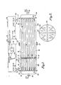
- Figure 1 is a schematic representation of a freeze crystallizer embodying the present invention. One mode of operation is depicted.
- Figure 2 is a section taken along lines 2-2 in Figure 1.
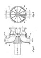
- Figure 3 is a schematic representation of an embodiment using balls as scrapers.
- Figure 4 is an enlarged sectional view of the Figure 3 strainer.
- Figure 5 is a section taken along lines 5-5 in Figure 4.
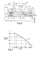
- Figure 6 is yet another embodiment utilizing individual shuttle scrapers.
- Figure 7 is a curve useful to describe the operation of the Figure 6 embodiment.
- Referring to Figure 1, there is shown a
freeze crystallizer subassembly 10 containing a heat exchanger orcrystallizer 12, a reservoir ormixer 14, apump 9, and an assortment of valves and conduits to be identified below. - The
crystallizer 12 contains typically one or morerefrigerant compartments 18 through which refrigerant is circulated from aninput 19 and out through an exit 21. Aleft plenum 22 and aright plenum 24 are connected by one (or more)tubes 20 through which refrigerant is circulated. - Slurry is supplied to the crystallizer by either of
ports tubes 20 in thespaces 18. In the aggregate, a slurry compartment is formed. - A piston 23 (see Figures 1 and 2) is situated within the
spaces 18 and contains a plurality ofholes 25 through whichtubes 20 pass.Piston 23 is thus able to move longitudinally relative to thetubes 20. -
Piston 23 is a double-walled structure containingscraper granules 26 between the walls which are in contact with the exterior surfaces 16 of thetubes 20. The scraper granules remove solute crystals from these surfaces as thepiston 23 moves relative to thetubes 20. A pair ofplugs 27 are provided to fill thepiston 23 withgranules 26 when the piston is positioned between theplugs 27. -
Numerals - The
reservoir 14 is supplied feed throughconduit 11. Slurry is removed from thecrystallizer subassembly 10 through theconduit 13. In this Figure 1, the slurry is carried from thereservoir 14 bypump 9 throughconduit 38 to openvalve 32 to theright port 17. The flow of slurry intoport 17 moves thepiston 23 to the left towardleft port 15. As it traverses over thetubes 20, it scrapes crystals from the exterior surfaces 16. The slurry ahead of the shuttle leaves throughport 15 throughopen valve 33 and returns to thereservoir 14 throughconduit 50. - When the
piston 23 reaches theport 15, a control circuit (not shown) rotatesvalve 32 andvalve 33 so that slurry will flow through the dashedpaths pump 9 now supplies slurry throughvalve 33 viapath 34. The flow of slurry from left to right moves thepiston 23 to the right. Then slurry ahead of thepiston 23 leaves theheat exchanger 12 throughvalve 32 viapath 30 and returns to thereservoir 14 andconduit 36. - When the freeze crystallizer subassembly is first turned on, the fluid flowing through the freeze crystallizer contains no crystals. Eventually crystals are formed and moved to the
reservoir 14. In practice, preferably 10 percent of the slurry flowing through thecrystallizer 12 is continuously removed for further treatment throughvalve 35 andconduit 13. The remainder is recirculated from thereservoir 14 to thecrystallizer 12, and more crystals are produced. Up to 25 percent of the slurry may be removed from thereservoir 14 and the remainder recirculated through thecrystallizer 12. Preformed crystals grow. The feed makes up for the loss of the slurry removed from the subassembly for further treatment. - Eventually, a steady-state condition occurs wherein a slurry exists in the
reservoir 14 andcrystallizer 12. Feed is supplied throughconduit 11 to replace the slurry removed from thereservoir 14. The ratio of crystals to mother liquor will vary depending on the concentration of the feedstream and the freezing temperature of thecrystallizer 12. The discussion assumes a steady-state condition. - Referring now to Figures 3, 4, and 5, an alternate embodiment of the invention will be described. In the apparatus of Figure 3, a unidirectional flow crystallizer is shown. The crystallizer is provided with an inlet for refrigerant at 68 and an outlet at 70. refrigerant at a low temperature is introduced at 68 and circulated around the exterior of
tubes 74. Slurry is circulated throughtubes 74 byrecirculation pump 60. The inlet port to the crystallizer is at 86. Thus recirculation pump 60 pumps slurry alongconduit 61 into theinlet port 86 throughrotatable strainer wheel 91 alongconduit 64 and intochamber 78 ofcrystallizer 66. - Along with the slurry, a plurality of objects such as
nylon balls crystallizer 66. - In applications providing ice crystals or other nontenacious films, rigid balls can be used. In heat exchanger cleaning where scale is being removed at infrequent intervals (minutes), the scale buildup varies with time between cleaning. Further, it will vary as a function of the contents in the liquid. The buildup along the length of a particular tube will also vary.
- In the case of scale, it is necessary to totally remove the scale because it inhibits heat transfer to and from the fluid in bulk flow; whereas in crystallization, the desired reaction is the formation of crystals at the heat transfer surface.
- The nonuniformity of scale mandates the use of nonrigid scrapers and scrapers dimensionally larger than the tubes. The clearance and lack of rigidity permit the scrapers to clean nonuniform films and films of varying thickness. Unexpectedly, continuous scraping of very thin and weakly-adhering films such as ice permits the use of rigid, unyielding scrapers with a small clearance between the scraper and the tube.
- Furthermore, the crystallizer chamber is partitioned into two segments-an
upper inlet segment 78 and alower outlet segment 80. The balls, or similar rigid objects, 72, are caused to flow throughtubes 74 from left to right as viewed in Figure 3 and then are sucked out the lower half of the crystallization chamber bypump 60 through the lower outlet segment oftubes 74 intolower chamber 80 throughconduit 82 and into the rotatable strainer wheel section where they are entrapped by thestrainer wheel 91 and prevented by thescreen 96 from being discharged through thedischarge port 84 and outconduit 63. - The
screen 96 is capable of being rotated bymotor 88 which is rotatably attached to therotating wheel 91. This wheel may be continuously rotated, or periodically rotated, such that, asballs 72 are accumulated in the lower portion or discharge section of the crystallizer apparatus, they are carried up to the inlet section and recirculated throughtubes 74. In this manner, there is provided a continuous flow of scraper objects through thetubes 74 to scrape buildup of crystallized ice on the interior surfaces of saidtubes 74. - Holes or slots (see Figure 5) are provided in the
rotating screen 96 sufficiently large to permit scraped ice particles to pass through the strainer, yet prevent the scraper objects 72 from passing through. Note: For simplicity, only one set of slots are shown in Figure 5. However, it should be understood that 12 such sets as in the case shown are utilized in the screen. Seal bars 94 radiate axially from thehub 93 of thestrainer wheel 91. These seal bars prevent the slurry at theinlet port 86 from passing directly to theoutlet port 84. - Figure 6 shows a
freeze crystallization subassembly 110 wherein each tube carrying slurry has its own individual shuttle for scraping the heat transfer surface clean of crystals. A feature of this system is a means for assuring that all the shuttles reach the end of their travel before the flow of slurry is reversed. - As before, feed is supplied via a conduit 111 to a
reservoir 114 and slurry is removed via a conduit 113. - A
pump 116 removes slurry from thereservoir 114 and supplies slurry to the freeze crystallizer 112 viaconduit 138 andopen valve 132 to aplenum 122. Refrigerant is supplied to the crystallizer 112 through theopening 121 and removed through theopening 119. - A plurality of aligned
tubes 123 traverse the length of the crystallizer 112 opening intoplenum 122 on the left and aright plenum 124. Slurry is circulated through the crystallizer 112 through thetubes 123. - Disposed in each tube is a
shuttle 126 which is designed to reciprocate throughtubes 123 and scrape crystals from theheat transfer surface 129 of the tubes. Eachshuttle 126 contains left andright stops stops - Referring to Figure 6, all of the
shuttles 126 are shown at the left end of their travel. Sincevalve 132 is open, thepump 116 is supplying slurry toplenum 122. The movement of-slurry intoplenum 122 will move the shuttles toward the right. The slurry within thetubes 123 ahead of the shuttle will exit viaplenum 124 and return to thereservoir 114 viaopen valve 134 andconduit 150. - Ideally, all of the shuttles will move uniformly through the
tubes 123 and arrive at the right terminus at about the same time. When this happens, consistently all of the tubes are scraped uniformly and with the utmost efficiency. - One, however, has to anticipate that such uniformity will not occur. So it is necessary to take measures to assure that all shuttles 126 will terminate their travel in the time alloted by the control system. In this case, the control can be no more complicated than a timing device which will alternately open
valves valves - The dotted outlines of
shuttles 126 near the right terminus illustrate that the central shuttle is lagging, for whatever reason, behind the other two which have reached the terminus. Since it is likely that crystals will continue to build up on theheat transfer surface 129A to the right of the center shuttle unless it is scraped, it is also likely that the center shuttle will have increasing difficulty scraping this portion of the tubes unless the shuttle is pushed to the right terminus. - The means for assuring that each shuttle will completely traverse its particular tube is embodied in this case in the
pump 116. This pump is a centrifugal pump with a steep head versus capacity curve. Such pumps are available in industry. A positive displacement pump could be used and generally has a steeper head versus capacity curve. Referring to Figure 7, there is acurve 118 which represents the head or pressure built up in thepump 116 as a function of the amount of slurry flowing through the pump. When 100 percent of its design flow occurs, the head built up in the pump is at A. If, for some reason the flow is decreased to 50 percent, the head built up in the pump is at higher valve C. At 25 percent flow, a still higher head D is generated. - In the case illustrated in Figure 6, it may be presumed that 33 percent of the slurry circulated through the crystallizer flows through each of the three
tubes 123. When all the shuttles are moving through the tubes at the same rate, it may be presumed that the head or pressure built up in the pump is at A. In the case illustrated, two of theshuttles 126 have ended their travel while the center shuttle appears hung up. The shuttles at the right terminus will act as blockage decreasing or stopping the flow of slurry in their respective tubes. When this happens, the flow of slurry through the crystallizer drops at least two thirds. - If the center shuttle is totally hung up, the flow of slurry through the crystallizer drops to zero. The head or pressure in the
pump 116 in this case will build up to a level above D which represents a flow rate of 25 percent. The higher than normal pressure against the center shuttle will break it loose and move it toward the right terminus. If normal movement of the center shuttle is resumed, it may be presumed that the driving pressure will continue to be as high as at C and accelerate the shuttle to the end of its travel. - The various features and advantages of the invention are thought to be clear from the foregoing description. Various other features and advantages not specifically enumerated will undoubtedly occur to those versed in the art, as likewise will many variations and modifications of the preferred embodiment illustrated.
Claims (15)
Applications Claiming Priority (2)
| Application Number | Priority Date | Filing Date | Title |
|---|---|---|---|
| US06/371,658 US4468930A (en) | 1982-04-26 | 1982-04-26 | Freeze crystallization subassembly |
| US371658 | 1982-04-26 |
Publications (3)
| Publication Number | Publication Date |
|---|---|
| EP0107705A1 EP0107705A1 (en) | 1984-05-09 |
| EP0107705A4 EP0107705A4 (en) | 1984-09-11 |
| EP0107705B1 true EP0107705B1 (en) | 1990-04-11 |
Family
ID=23464880
Family Applications (1)
| Application Number | Title | Priority Date | Filing Date |
|---|---|---|---|
| EP83901679A Expired EP0107705B1 (en) | 1982-04-26 | 1983-04-14 | Process for producing a slurry containing concentrated liquid and ice crystals and subassembly therefor |
Country Status (6)
| Country | Link |
|---|---|
| US (1) | US4468930A (en) |
| EP (1) | EP0107705B1 (en) |
| CA (1) | CA1193592A (en) |
| DE (1) | DE3381442D1 (en) |
| IT (1) | IT1161166B (en) |
| WO (1) | WO1983003892A1 (en) |
Families Citing this family (22)
| Publication number | Priority date | Publication date | Assignee | Title |
|---|---|---|---|---|
| JPS63277166A (en) * | 1987-05-09 | 1988-11-15 | Hitachi Ltd | Chip electronic parts feeder |
| IL94289A (en) * | 1990-05-04 | 1992-12-01 | Balls Technics Ltd | Cleaning system for cleaning fluid-conducting tubing |
| US5953924A (en) * | 1991-06-17 | 1999-09-21 | Y. T. Li Engineering, Inc. | Apparatus, process and system for tube and whip rod heat exchanger |
| US5363660A (en) * | 1991-06-17 | 1994-11-15 | Y. T. Li Engineering, Inc. | Orbital type freezing apparatus and method |
| US5385645A (en) * | 1991-06-17 | 1995-01-31 | Y. T. Li Engineering, Inc. | Heat transfer apparatus with positive drive orbital whip rod |
| US5768894A (en) * | 1991-06-17 | 1998-06-23 | Y.T. Li Engineering, Inc. | Apparatus, process and system for tube and whip rod heat exchanger |
| US8352400B2 (en) | 1991-12-23 | 2013-01-08 | Hoffberg Steven M | Adaptive pattern recognition based controller apparatus and method and human-factored interface therefore |
| US10361802B1 (en) | 1999-02-01 | 2019-07-23 | Blanding Hovenweep, Llc | Adaptive pattern recognition based control system and method |
| US5394706A (en) * | 1993-05-20 | 1995-03-07 | Waterworks International, Inc. | Freeze crystallization for the removal of water from a solution of dissolved solids |
| CN1085827C (en) * | 1993-06-22 | 2002-05-29 | 李耀滋公司 | heat exchanger |
| NL1001050C2 (en) * | 1995-08-24 | 1997-02-25 | Grenco B V | The on-board refrigeration of fish after capture |
| WO1998043716A2 (en) * | 1997-03-31 | 1998-10-08 | Waterworks International, Inc. | Sulfuric acid purification process |
| US5799622A (en) * | 1997-06-30 | 1998-09-01 | Decker Manufacturing | Furnace heat exchanger tube cleaning system |
| ES2158752B1 (en) | 1998-07-16 | 2002-06-16 | Hrs Spiratube S L | IMPROVEMENTS IN THERMAL EXCHANGERS FOR TREATMENT OF LIQUIDS. |
| US5971061A (en) * | 1998-09-21 | 1999-10-26 | Y.T. Li Engineering, Inc. | Edge-hanging orbital rod support and drive for vertical tube-type heat exchanger |
| US7904187B2 (en) | 1999-02-01 | 2011-03-08 | Hoffberg Steven M | Internet appliance system and method |
| US6604577B2 (en) * | 2000-12-05 | 2003-08-12 | Eric P. Mulder | Geothermal heat pump cleaning control system and method |
| CN104864770A (en) * | 2015-05-27 | 2015-08-26 | 武汉工程大学 | Online cleaning system and method for circulating cooling water heat exchanger |
| US20180328661A1 (en) * | 2017-05-11 | 2018-11-15 | Larry Baxter | Method for Removing Foulants from a Heat Exchanger through Coolant Flow Control |
| CN109556447A (en) * | 2017-09-26 | 2019-04-02 | 北京奥博水处理有限责任公司 | Self-cleaning heat exchanger |
| US12054403B2 (en) * | 2020-09-22 | 2024-08-06 | Roc Water Technologies (Pty) Ltd | Treatment of water |
| CN114623704A (en) * | 2022-03-04 | 2022-06-14 | 德帕姆(杭州)泵业科技有限公司 | Tubular heat exchanger |
Family Cites Families (12)
| Publication number | Priority date | Publication date | Assignee | Title |
|---|---|---|---|---|
| US2066431A (en) * | 1935-02-02 | 1937-01-05 | Reconstruction Finance Corp | Ice making apparatus |
| US2890239A (en) * | 1954-07-15 | 1959-06-09 | Phillips Petroleum Co | Separation by crystallization |
| FR1308703A (en) * | 1961-09-27 | 1962-11-09 | Mechanical cleaning device for the outer surface of tubes | |
| US3259179A (en) * | 1964-04-06 | 1966-07-05 | John M Leach | Tube cleaner |
| US3342040A (en) * | 1966-05-25 | 1967-09-19 | Manitowoc Co | Apparatus for making frozen products |
| US3406741A (en) * | 1966-11-14 | 1968-10-22 | John M. Leach | Process and apparatus for treating liquids |
| US3507319A (en) * | 1968-04-17 | 1970-04-21 | Abraham Kogan | Method and apparatus for effecting heat transfer |
| DE2127715C3 (en) * | 1971-06-04 | 1980-02-28 | Maschinenfabrik Augsburg-Nuernberg Ag, 8900 Augsburg | Tube heat exchanger with cleaning bodies for periodic cleaning of the cooling tubes |
| US4124065A (en) * | 1976-11-04 | 1978-11-07 | Water Services Of America, Inc. | Apparatus for cleaning heat exchanger tubes |
| US4192151A (en) * | 1977-09-07 | 1980-03-11 | Vivian Manufacturing Company | Ice making apparatus |
| US4269264A (en) * | 1978-07-03 | 1981-05-26 | Water Services Of America, Inc. | Cleaning of heat exchanger tubing |
| DE3207466A1 (en) * | 1982-03-02 | 1983-09-15 | Taprogge Gesellschaft mbH, 4000 Düsseldorf | DEVICE FOR CLEANING HEAT EXCHANGER TUBES AND METHOD FOR OPERATING SUCH A DEVICE |
-
1982
- 1982-04-26 US US06/371,658 patent/US4468930A/en not_active Expired - Lifetime
-
1983
- 1983-04-14 DE DE8383901679T patent/DE3381442D1/en not_active Expired - Lifetime
- 1983-04-14 WO PCT/US1983/000557 patent/WO1983003892A1/en not_active Ceased
- 1983-04-14 EP EP83901679A patent/EP0107705B1/en not_active Expired
- 1983-04-18 CA CA000426073A patent/CA1193592A/en not_active Expired
- 1983-04-22 IT IT20754/83A patent/IT1161166B/en active
Also Published As
| Publication number | Publication date |
|---|---|
| DE3381442D1 (en) | 1990-05-17 |
| EP0107705A4 (en) | 1984-09-11 |
| IT8320754A0 (en) | 1983-04-22 |
| IT8320754A1 (en) | 1984-10-22 |
| US4468930A (en) | 1984-09-04 |
| IT1161166B (en) | 1987-03-11 |
| EP0107705A1 (en) | 1984-05-09 |
| CA1193592A (en) | 1985-09-17 |
| WO1983003892A1 (en) | 1983-11-10 |
Similar Documents
| Publication | Publication Date | Title |
|---|---|---|
| US4468930A (en) | Freeze crystallization subassembly | |
| US5394706A (en) | Freeze crystallization for the removal of water from a solution of dissolved solids | |
| JP4062374B2 (en) | Ice maker | |
| AU2001280042B2 (en) | Method and installation for continuous crystallization of liquids by freezing | |
| US20020194865A1 (en) | Apparatus for producing potable water and slush from sea water or brine | |
| AU2001280042A1 (en) | Method and installation for continuous crystallization of liquids by freezing | |
| EP0730893B1 (en) | Freeze crystallization concentration methods and apparatus | |
| CN112316476A (en) | Cold crystallizer | |
| US1576137A (en) | Apparatus for concentrating soulutions | |
| CN118757963A (en) | A hybrid seawater ice making machine | |
| CN115228128A (en) | A kind of interface progressive freeze-concentration device and concentration method with continuous deicing | |
| CN106865670A (en) | Using the freezing sea water desalinating unit system of heterogeneous sedimentation crystallization nucleation mode | |
| JPH0343559B2 (en) | ||
| CN112875966A (en) | Energy-saving saline-alkali water multistage freezing desalination device and process | |
| JP2000258005A (en) | Method and apparatus for manufacturing and transporting grain ice | |
| JPH0248090A (en) | Water desalting device | |
| US3398548A (en) | Vacuum freeze solution separation system | |
| US4809519A (en) | Methods and apparatuses for conducting solid-liquid-vapor multiple phase transformation operations | |
| KR20180053183A (en) | System for producing electrolytic water ice slurry | |
| KR101949235B1 (en) | System for producing electrolytic water ice slurry | |
| JP3544270B2 (en) | How to freeze aqueous solution | |
| NL1001050C2 (en) | The on-board refrigeration of fish after capture | |
| CA1286888C (en) | Method and apparatus for cooling fish on board a ship | |
| RU2034614C1 (en) | Crystallizer | |
| DE2414586C3 (en) | Method and device for separating solid materials from a liquid phase of a mixture by heat transfer |
Legal Events
| Date | Code | Title | Description |
|---|---|---|---|
| PUAI | Public reference made under article 153(3) epc to a published international application that has entered the european phase |
Free format text: ORIGINAL CODE: 0009012 |
|
| 17P | Request for examination filed |
Effective date: 19831122 |
|
| AK | Designated contracting states |
Designated state(s): DE FR GB NL |
|
| 18R | Application refused |
Effective date: 19860823 |
|
| D18R | Application refused (deleted) | ||
| GRAA | (expected) grant |
Free format text: ORIGINAL CODE: 0009210 |
|
| AK | Designated contracting states |
Kind code of ref document: B1 Designated state(s): DE FR GB NL |
|
| REF | Corresponds to: |
Ref document number: 3381442 Country of ref document: DE Date of ref document: 19900517 |
|
| ET | Fr: translation filed | ||
| RAP2 | Party data changed (patent owner data changed or rights of a patent transferred) |
Owner name: CONCENTREX, INC. |
|
| NLXE | Nl: other communications concerning ep-patents (part 3 heading xe) |
Free format text: IN PAT.BUL.13/90,PAGES 1791 AND 1815:CORR.:CONCENTREX, INC. |
|
| RAP2 | Party data changed (patent owner data changed or rights of a patent transferred) |
Owner name: FREEZE CONCENTRATION INC. |
|
| PLBE | No opposition filed within time limit |
Free format text: ORIGINAL CODE: 0009261 |
|
| STAA | Information on the status of an ep patent application or granted ep patent |
Free format text: STATUS: NO OPPOSITION FILED WITHIN TIME LIMIT |
|
| NLT2 | Nl: modifications (of names), taken from the european patent patent bulletin |
Owner name: FREEZE CONCENTRATION INC. TE IPSWICH, MASSACHUSETT |
|
| 26N | No opposition filed | ||
| NLS | Nl: assignments of ep-patents |
Owner name: PLANT RESOURCES VENTURE FUND TE CAMBRIDGE, MASSACH |
|
| NLS | Nl: assignments of ep-patents |
Owner name: FREEZE CONCENTRATION INC. TE IPSWICH, MASSACHUSETT |
|
| REG | Reference to a national code |
Ref country code: GB Ref legal event code: 732 |
|
| REG | Reference to a national code |
Ref country code: GB Ref legal event code: 732 |
|
| NLS | Nl: assignments of ep-patents |
Owner name: SOCIETE DES PRODUITS NESDTLE S.A. TE VEVEY, ZWITSE |
|
| REG | Reference to a national code |
Ref country code: FR Ref legal event code: TP |
|
| PGFP | Annual fee paid to national office [announced via postgrant information from national office to epo] |
Ref country code: NL Payment date: 19980428 Year of fee payment: 16 |
|
| PG25 | Lapsed in a contracting state [announced via postgrant information from national office to epo] |
Ref country code: NL Free format text: LAPSE BECAUSE OF NON-PAYMENT OF DUE FEES Effective date: 19991101 |
|
| NLV4 | Nl: lapsed or anulled due to non-payment of the annual fee |
Effective date: 19991101 |
|
| REG | Reference to a national code |
Ref country code: GB Ref legal event code: IF02 |
|
| PGFP | Annual fee paid to national office [announced via postgrant information from national office to epo] |
Ref country code: GB Payment date: 20020410 Year of fee payment: 20 Ref country code: FR Payment date: 20020410 Year of fee payment: 20 |
|
| PGFP | Annual fee paid to national office [announced via postgrant information from national office to epo] |
Ref country code: DE Payment date: 20020417 Year of fee payment: 20 |
|
| PG25 | Lapsed in a contracting state [announced via postgrant information from national office to epo] |
Ref country code: GB Free format text: LAPSE BECAUSE OF EXPIRATION OF PROTECTION Effective date: 20030413 |
|
| REG | Reference to a national code |
Ref country code: GB Ref legal event code: PE20 |
|
| APAH | Appeal reference modified |
Free format text: ORIGINAL CODE: EPIDOSCREFNO |