EP0107596B1 - Balise de détresse pour naufrage - Google Patents
Balise de détresse pour naufrage Download PDFInfo
- Publication number
- EP0107596B1 EP0107596B1 EP19830402079 EP83402079A EP0107596B1 EP 0107596 B1 EP0107596 B1 EP 0107596B1 EP 19830402079 EP19830402079 EP 19830402079 EP 83402079 A EP83402079 A EP 83402079A EP 0107596 B1 EP0107596 B1 EP 0107596B1
- Authority
- EP
- European Patent Office
- Prior art keywords
- frequency
- antenna
- transmitters
- transmitter
- switching
- Prior art date
- Legal status (The legal status is an assumption and is not a legal conclusion. Google has not performed a legal analysis and makes no representation as to the accuracy of the status listed.)
- Expired - Lifetime
Links
- 230000009429 distress Effects 0.000 title claims description 15
- 230000005540 biological transmission Effects 0.000 claims description 7
- 238000010586 diagram Methods 0.000 description 8
- 238000001514 detection method Methods 0.000 description 3
- 239000010453 quartz Substances 0.000 description 2
- VYPSYNLAJGMNEJ-UHFFFAOYSA-N silicon dioxide Inorganic materials O=[Si]=O VYPSYNLAJGMNEJ-UHFFFAOYSA-N 0.000 description 2
- 230000006978 adaptation Effects 0.000 description 1
- 230000000712 assembly Effects 0.000 description 1
- 238000000429 assembly Methods 0.000 description 1
- 230000033228 biological regulation Effects 0.000 description 1
- 239000003990 capacitor Substances 0.000 description 1
- 230000015556 catabolic process Effects 0.000 description 1
- 239000013078 crystal Substances 0.000 description 1
- 230000007423 decrease Effects 0.000 description 1
- 230000009977 dual effect Effects 0.000 description 1
- 230000000694 effects Effects 0.000 description 1
- 230000004807 localization Effects 0.000 description 1
- 238000012544 monitoring process Methods 0.000 description 1
- 230000008520 organization Effects 0.000 description 1
- 238000009304 pastoral farming Methods 0.000 description 1
- 230000005855 radiation Effects 0.000 description 1
- 238000001228 spectrum Methods 0.000 description 1
- 238000006467 substitution reaction Methods 0.000 description 1
- XLYOFNOQVPJJNP-UHFFFAOYSA-N water Substances O XLYOFNOQVPJJNP-UHFFFAOYSA-N 0.000 description 1
Images
Classifications
-
- G—PHYSICS
- G01—MEASURING; TESTING
- G01S—RADIO DIRECTION-FINDING; RADIO NAVIGATION; DETERMINING DISTANCE OR VELOCITY BY USE OF RADIO WAVES; LOCATING OR PRESENCE-DETECTING BY USE OF THE REFLECTION OR RERADIATION OF RADIO WAVES; ANALOGOUS ARRANGEMENTS USING OTHER WAVES
- G01S5/00—Position-fixing by co-ordinating two or more direction or position line determinations; Position-fixing by co-ordinating two or more distance determinations
- G01S5/02—Position-fixing by co-ordinating two or more direction or position line determinations; Position-fixing by co-ordinating two or more distance determinations using radio waves
- G01S5/0205—Details
- G01S5/0226—Transmitters
- G01S5/0231—Emergency, distress or locator beacons
Definitions
- the present invention relates to distress beacons for shipwrecked persons, that is to say instruments of the "radiolocation transmitter” type, making it possible to locate their wearer by means of an appropriate receiver.
- instruments of the "radiolocation transmitter” type that is to say instruments of the "radiolocation transmitter” type, making it possible to locate their wearer by means of an appropriate receiver.
- radiolocation transmitters operating on aviation distress frequencies.
- radiolocation transmitters can be fixed or portable, high or low power.
- portable units these allow, thanks to the permanent listening carried out by the aeronautical services equipped with professional and efficient receivers, to search, locate and rescue a shipwrecked person alone at sea.
- frequency distribution has been organized so as to allocate in the VHF or metric band the frequency spectrum from 156.025 MHz to 162.025 MHz for coastal traffic.
- This channel 16 of frequency 156.800 MHz has become frequency, international used for distress, safety and calls by the service maritime mobile (EBU: European Broadcasting Union).
- the following invention overcomes this drawback by the emission of a third distress or emergency frequency, that is to say the information necessary for rapid detection, near or offshore, of a shipwrecked alone at sea by the maritime services or any vessel within a specified distance. It also makes it possible to preserve the possibilities offered by aeronautics.
- a distress beacon of the radiolocation transmitter type comprising a power supply, a switching and modulation unit, a frequency modulation transmitter and an antenna.
- the switching and modulation device is arranged to control the programs alternately with a period of silence between each program.
- US Pat. No. 3,665,315 in a similar application, a distress transmitter operating in amplitude modulation simultaneously delivering signals of 121.5 and 243 MHz.
- the subject of the present invention is a distress beacon of the radiolocation transmitter type comprising a power supply, a switching and modulation device, an amplitude modulation transmitter, a frequency modulation transmitter and an antenna, the switching device and modulations being arranged to control the transmissions of the transmitters preferably alternately, with a period of silence between each emission, the antenna being a shortened quarter-wave antenna whose tuning frequency is central, that is to say say substantially equal to the frequency equidistant from the frequency FM and the base frequency AM, and each circuit of the power stages having reciprocally, by their tuned circuits, a total mismatch for the other frequency so that during the alternating operation of the transmitters, the output power chooses the most suitable path, that of the antenna.
- This radiobeacon is of the tri-frequency type, the two aeronautical frequencies of 121.500 MHz and 245 MHz being transmitted simultaneously.
- the third frequency of 156.800 MHz is switched alternately with the first two following a cycle which can be for example 5 seconds (see Figure 2).
- a transmission period is preferably followed by a period of silence to save the battery.
- the periods can be equal; each transmitter transmits continuously during one out of two of the transmission periods.
- Each transmitter uses for its modulation an acoustic signal of 1300 hz cut to obtain a ratio equal to or greater than at least 1/2 (European Union Broadcasting Convention).
- This tri-frequency beacon has two modulation modes.
- the aviation distress frequency radiolocation transmitter is amplitude modulated, the second frequency of 243 MHz being the harmonic 2 of 121.5 MHz which is favored by the non-linearity effect of the output stage.
- the 156.800 MHz frequency radiolocation transmitter is frequency modulated.
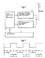
- the portable assembly is waterproof and buoyant and is weighted so as to keep the antenna out of the water. It therefore comprises two transmitters switched alternately and modulated in amplitude or in frequency according to the diagram in FIG. 1 and the diagram in FIG. 2.
- the device includes a power supply 1 debiting on a switching and modulation card 2 controlling the aviation transmitter 3, operating in amplitude modulation on the frequencies 121.5 MHz and 243 MHz and the marine transmitter 4 operating in modulation of amplitude on the frequency 156.8 MHz.
- the two transmitters are coupled to the single antenna 5.
- the diagram in Figure 2 illustrates an example of how the device works. Periods of silence of five seconds are separated by periods of emission of five seconds. These periods are chosen equal, but may be different. In particular, the emission periods can be spaced apart when the battery charge decreases, to extend the useful life of the device. Conversely, the period of silence may be shorter, or even zero. The importance of the emission period favors localization.
- the switching and modulating member 2 may include switching means sensitive to the residual charge of the power supply (that is to say a voltage threshold detector and an appropriate control circuit).
- the aviation transmitter works, and during the other period, it is the marine transmitter.
- the power of the FM transmitter is greater than that of the AM transmitter, the maritime services tracking and detection systems being terrestrial, while aeronautical tracking is carried out at altitude.
- This characteristic tends to compensate for the differences in sight and grazing propagation: no obstacle towards the sky.
- the cutting and modulation of the two transmitters is carried out by a minimum of electronic components for reasons of reliability and consumption.
- the basic oscillators and the modulation remain in permanent operation when the beacon is started up for reasons of frequency stability.
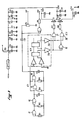
- Figure 3 shows in more detail the composition of the modulation and cutting card.
- a single integrated circuit IC1 is the master pilot, its first two NAND gates 11, 12 are mounted as a multivibrator and provide a square frequency signal This square signal of ratio equal to or greater than unity controls the triggering of the acoustic frequency multivibrator constituted by the other two doors 13, 14 of the same circuit and a seven-stage counter IC2, only two of which are shown.
- this counter makes it possible, by the choice of its associated outputs two by two, to be able to vary the operating alternations of stopping the transmitters.
- the outputs S5 and S6 of IC2 control a group of three NAND gates 16, 17, 18 in order to achieve the alternation described in diagram 2.
- the two gates 17, 18 drive the switching transistors (T1 and T2, Figure 3) of the transmitters' power supplies, and make it possible to invert the choice of emissions which always remains linked to that of the modulation breakdown.
- By choosing two other neighboring doors we can have different emission times, but equal to the silence times.
- By a judicious choice of non-neighboring doors it is possible to vary the transmission times with respect to the silence times. This choice can be made by a circuit controlled by a voltage threshold detector.
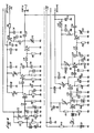
- the electronic implementation comprises two separate transmitter assemblies (see FIG. 4). These are of classic design: a quartz oscillator stage (Q1 or Q2) followed by a doubler stage, then an amplifier buffer stage which precedes the final power stage.
- the crystal oscillator stage is modulated by the acoustic signal applied to a varicap diode D1 associated with a self-series L6 in order to increase the frequency excursion.
- AM mode it is the final stage which is modulated by the use of a serial modulator consisting of a transistor T5.
- the two final transistors T4 and T9 of the two transmitters are tuned in their collectors by the circuits L5, C V2 and L11, C V3 on their respective frequencies ( Figure 3). They are strongly coupled by capacitors C 17 and C 34 to a single antenna 5 in shortened quarter wave (spiral) whose tuning frequency is central, that is to say a frequency as close as possible to the equidistant frequency of 121.5 and 156.8 or 139.15.
- the antenna has the same mismatch for the respective frequencies of 121.5 MHz and 156.8 MHz but really behaves like an antenna.
- Each tuned circuit of the power stages presents reciprocally during the alternating operation of the transmitters, a total mismatch for the other frequency by means of their tuned circuits.
- the output power of each set chooses the most suitable path; that of the antenna.
- the beacon may include a satellite-aviation switch; the initial position being for example satellite, the shipwrecked switch to aviation if he sees an airplane.
- the quartz oscillator could be replaced by a frequency synthesizer, which the switching card would control in order to obtain the different distress frequencies, existing or to come.
Landscapes
- Physics & Mathematics (AREA)
- Engineering & Computer Science (AREA)
- General Physics & Mathematics (AREA)
- Radar, Positioning & Navigation (AREA)
- Remote Sensing (AREA)
- Transmitters (AREA)
Applications Claiming Priority (2)
| Application Number | Priority Date | Filing Date | Title |
|---|---|---|---|
| FR8217774 | 1982-10-25 | ||
| FR8217774A FR2535065A1 (fr) | 1982-10-25 | 1982-10-25 | Balise de detresse pour naufrage |
Publications (2)
| Publication Number | Publication Date |
|---|---|
| EP0107596A1 EP0107596A1 (fr) | 1984-05-02 |
| EP0107596B1 true EP0107596B1 (fr) | 1990-08-08 |
Family
ID=9278543
Family Applications (1)
| Application Number | Title | Priority Date | Filing Date |
|---|---|---|---|
| EP19830402079 Expired - Lifetime EP0107596B1 (fr) | 1982-10-25 | 1983-10-25 | Balise de détresse pour naufrage |
Country Status (3)
| Country | Link |
|---|---|
| EP (1) | EP0107596B1 (enExample) |
| DE (1) | DE3381795D1 (enExample) |
| FR (1) | FR2535065A1 (enExample) |
Families Citing this family (6)
| Publication number | Priority date | Publication date | Assignee | Title |
|---|---|---|---|---|
| EP0194063A3 (en) * | 1985-02-18 | 1987-11-19 | Plessey Overseas Limited | Tracking transmitter with two operational modes |
| FR2836722B1 (fr) * | 2002-03-01 | 2006-12-08 | Airbus France | Balise de detresse, procede et dispositif de surveillance de signaux de detresse, et vehicule comprenant un tel dispositif |
| RU2282870C1 (ru) * | 2005-01-12 | 2006-08-27 | Вячеслав Адамович Заренков | Аварийный радиобуй |
| WO2008012377A1 (es) * | 2006-07-28 | 2008-01-31 | Indra Sistemas, S.A | Sistema localizador que utiliza radiobalizas personales |
| RU2453860C1 (ru) * | 2011-04-20 | 2012-06-20 | Открытое акционерное общество "Научно-исследовательский институт космического приборостроения " (ОАО "НИИ КП") | Устройство для измерения технических параметров аварийных радиомаяков/радиобуев |
| RU2496116C1 (ru) * | 2012-05-14 | 2013-10-20 | Открытое акционерное общество "Научно-исследовательский институт космического приборостроения" (ОАО "НИИ КП") | Аварийный радиобуй |
Family Cites Families (5)
| Publication number | Priority date | Publication date | Assignee | Title |
|---|---|---|---|---|
| GB1060173A (en) * | 1965-01-29 | 1967-03-01 | Standard Telephones Cables Ltd | Frequency diversity transmitting system |
| FR1544800A (fr) * | 1967-09-27 | 1968-11-08 | Sofelec Soc Pour La Realisatio | Appareil émetteur radioélectrique |
| US3665315A (en) * | 1969-09-03 | 1972-05-23 | Stephen G Glatzer | Signal transmitter |
| US3870959A (en) * | 1972-10-24 | 1975-03-11 | Baldwin Electronics Inc | Dual frequency transmitter system |
| US4101894A (en) * | 1976-09-17 | 1978-07-18 | Warner Melvin B Cy Marshall Ii | Radio beacon for a nautical emergency rescue system |
-
1982
- 1982-10-25 FR FR8217774A patent/FR2535065A1/fr active Granted
-
1983
- 1983-10-25 DE DE8383402079T patent/DE3381795D1/de not_active Expired - Fee Related
- 1983-10-25 EP EP19830402079 patent/EP0107596B1/fr not_active Expired - Lifetime
Also Published As
| Publication number | Publication date |
|---|---|
| FR2535065A1 (fr) | 1984-04-27 |
| EP0107596A1 (fr) | 1984-05-02 |
| DE3381795D1 (de) | 1990-09-13 |
| FR2535065B1 (enExample) | 1985-04-12 |
Similar Documents
| Publication | Publication Date | Title |
|---|---|---|
| CA1279374C (fr) | Systeme de transmission de signaux sismiques utilisant des radio relais | |
| EP0314101B1 (fr) | Système de transmission radiofréquence-optique, notamment dans le domaine des télécommunications spatiales | |
| EP0631400B1 (fr) | Dispositif d'émission/réception de signaux numériques portable bimode | |
| BE904995A (fr) | Radar a bruit. | |
| FR2529736A1 (fr) | Emetteur de brouillage | |
| CA1247216A (fr) | Radioaltimetre a modulation de frequence | |
| EP0107596B1 (fr) | Balise de détresse pour naufrage | |
| EP0172445B1 (fr) | Transpondeur passif, notamment pour la recherche de personnes victimes d'une avalanche | |
| EP0025739B1 (fr) | Aérien pour radar primaire et radar secondaire | |
| FR2574557A1 (fr) | Dispositif d'elimination de bruit basse frequence d'un systeme de transmission, en particulier de bruit en 1/f dans un recepteur radar homodyne | |
| FR2692363A1 (fr) | Procédé et dispositif de mesure de distances par émission d'ondes radioélectriques et ultrasonores. | |
| EP0142406B1 (fr) | Répondeur radar passif | |
| EP0532383B1 (fr) | Procédé et dispositif pour la transmission simultanée d'information entre des mobiles et une station de réception | |
| FR2805684A1 (fr) | Systeme de telecommunications a etalement de spectre | |
| FR2604046A1 (fr) | Emetteur radioelectrique susceptible d'emettre des informations d'identite | |
| FR2639167A1 (fr) | Procede et systeme de transmission d'un signal | |
| EP0074330A1 (fr) | Installation pour l'identification et la détermination de l'instant du passage d'une pluralité de mobiles en un point déterminé de leur trajectoire | |
| FR2527870A1 (fr) | Carte repondeuse codee, destinee a etre associee a un emetteur-recepteur de micro-ondes en particulier, en vue de l'identification d'objets | |
| RU2282897C1 (ru) | Sos-система для автомагистралей | |
| US4129869A (en) | Automatical signalling apparatus | |
| EP0083534B1 (fr) | Système d'atterrissage hyperfréquence à protection contre le brouillage | |
| EP0689301A1 (fr) | Système d'antennes d'émission-réception omnidirectionnel à diversité angulaire et de polarisation | |
| FR2644700A1 (fr) | Dispositif pour la detection et la localisation de victimes d'avalanches | |
| JPH01237482A (ja) | 捜索・救助用レーダ・トランスポンダ装置 | |
| RU2282870C1 (ru) | Аварийный радиобуй |
Legal Events
| Date | Code | Title | Description |
|---|---|---|---|
| PUAI | Public reference made under article 153(3) epc to a published international application that has entered the european phase |
Free format text: ORIGINAL CODE: 0009012 |
|
| AK | Designated contracting states |
Designated state(s): BE CH DE FR GB IT LI LU NL SE |
|
| 17P | Request for examination filed |
Effective date: 19841102 |
|
| 17Q | First examination report despatched |
Effective date: 19860527 |
|
| GRAA | (expected) grant |
Free format text: ORIGINAL CODE: 0009210 |
|
| AK | Designated contracting states |
Kind code of ref document: B1 Designated state(s): BE CH DE FR GB IT LI LU NL SE |
|
| PG25 | Lapsed in a contracting state [announced via postgrant information from national office to epo] |
Ref country code: SE Free format text: THE PATENT HAS BEEN ANNULLED BY A DECISION OF A NATIONAL AUTHORITY Effective date: 19900808 Ref country code: NL Effective date: 19900808 Ref country code: IT Free format text: LAPSE BECAUSE OF FAILURE TO SUBMIT A TRANSLATION OF THE DESCRIPTION OR TO PAY THE FEE WITHIN THE PRESCRIBED TIME-LIMIT;WARNING: LAPSES OF ITALIAN PATENTS WITH EFFECTIVE DATE BEFORE 2007 MAY HAVE OCCURRED AT ANY TIME BEFORE 2007. THE CORRECT EFFECTIVE DATE MAY BE DIFFERENT FROM THE ONE RECORDED. Effective date: 19900808 |
|
| REF | Corresponds to: |
Ref document number: 3381795 Country of ref document: DE Date of ref document: 19900913 |
|
| PG25 | Lapsed in a contracting state [announced via postgrant information from national office to epo] |
Ref country code: LU Free format text: LAPSE BECAUSE OF NON-PAYMENT OF DUE FEES Effective date: 19901031 Ref country code: BE Effective date: 19901031 |
|
| GBT | Gb: translation of ep patent filed (gb section 77(6)(a)/1977) | ||
| NLV1 | Nl: lapsed or annulled due to failure to fulfill the requirements of art. 29p and 29m of the patents act | ||
| BERE | Be: lapsed |
Owner name: DE TRAVAUX D'ORGANISATION ET DE GESTION SERTOG Effective date: 19901031 Owner name: DE RECHERCHES Effective date: 19901031 Owner name: SOC. D'ETUDES Effective date: 19901031 |
|
| PLBE | No opposition filed within time limit |
Free format text: ORIGINAL CODE: 0009261 |
|
| STAA | Information on the status of an ep patent application or granted ep patent |
Free format text: STATUS: NO OPPOSITION FILED WITHIN TIME LIMIT |
|
| PG25 | Lapsed in a contracting state [announced via postgrant information from national office to epo] |
Ref country code: DE Effective date: 19910702 |
|
| 26N | No opposition filed | ||
| PGFP | Annual fee paid to national office [announced via postgrant information from national office to epo] |
Ref country code: CH Payment date: 19941027 Year of fee payment: 12 |
|
| PG25 | Lapsed in a contracting state [announced via postgrant information from national office to epo] |
Ref country code: LI Effective date: 19951031 Ref country code: CH Effective date: 19951031 |
|
| REG | Reference to a national code |
Ref country code: CH Ref legal event code: PL |
|
| PGFP | Annual fee paid to national office [announced via postgrant information from national office to epo] |
Ref country code: GB Payment date: 19961024 Year of fee payment: 14 |
|
| PG25 | Lapsed in a contracting state [announced via postgrant information from national office to epo] |
Ref country code: GB Free format text: LAPSE BECAUSE OF NON-PAYMENT OF DUE FEES Effective date: 19971025 |
|
| GBPC | Gb: european patent ceased through non-payment of renewal fee |
Effective date: 19971025 |
|
| PGFP | Annual fee paid to national office [announced via postgrant information from national office to epo] |
Ref country code: FR Payment date: 20011029 Year of fee payment: 19 |
|
| PG25 | Lapsed in a contracting state [announced via postgrant information from national office to epo] |
Ref country code: FR Free format text: LAPSE BECAUSE OF NON-PAYMENT OF DUE FEES Effective date: 20030630 |
|
| REG | Reference to a national code |
Ref country code: FR Ref legal event code: ST |