EP0107590A1 - Überdruckwiederbelebungsgerät mit pneumatischer Regelung - Google Patents
Überdruckwiederbelebungsgerät mit pneumatischer Regelung Download PDFInfo
- Publication number
- EP0107590A1 EP0107590A1 EP19830402035 EP83402035A EP0107590A1 EP 0107590 A1 EP0107590 A1 EP 0107590A1 EP 19830402035 EP19830402035 EP 19830402035 EP 83402035 A EP83402035 A EP 83402035A EP 0107590 A1 EP0107590 A1 EP 0107590A1
- Authority
- EP
- European Patent Office
- Prior art keywords
- pressure
- cell
- outside
- chamber
- pneumatic
- Prior art date
- Legal status (The legal status is an assumption and is not a legal conclusion. Google has not performed a legal analysis and makes no representation as to the accuracy of the status listed.)
- Withdrawn
Links
Images
Classifications
-
- A—HUMAN NECESSITIES
- A61—MEDICAL OR VETERINARY SCIENCE; HYGIENE
- A61M—DEVICES FOR INTRODUCING MEDIA INTO, OR ONTO, THE BODY; DEVICES FOR TRANSDUCING BODY MEDIA OR FOR TAKING MEDIA FROM THE BODY; DEVICES FOR PRODUCING OR ENDING SLEEP OR STUPOR
- A61M16/00—Devices for influencing the respiratory system of patients by gas treatment, e.g. mouth-to-mouth respiration; Tracheal tubes
Definitions
- the present invention relates to resuscitation equipment such as artificial respirators and, more particularly, equipment of this type operating in closed spaces under pressure designated chambers or hyperbaric chambers.
- the invention relates to a device for controlling the volumetric flow rate, the frequency and the ratio of inspiration to expiration under conditions of overpressure, with total reliability.
- Hyperbaric chambers are used to revive patients whose condition requires special conditions such as overpressure, high oxygen content, etc., who strongly recommend avoiding electrical or electronic devices, regardless of explosion-proof precautions. It is therefore preferred to use entirely pneumatic devices. But, under the pressure conditions of the hyperbaric chambers, the pneumatic logics drift uncontrollably and it is no longer possible to ensure the stability of the I / E ratio (from the duration of inspiration to the duration of expiration), frequency and volumetric flow during the inspiration period. The volumetric flow rate must be independent of the pressure which can, depending on the applications, be from 1 to a few bars.
- the subject of the present invention is a resuscitator for a hyperbaric chamber, with pneumatic control, remarkable in particular in that it comprises a logic pneumatic cell, a gas supply member at constant constant pressure for controlling said cell, including the exhaust is returned to the outside of the hyperbaric chamber, the exhaust duct comprising a load resistor, and a bypass, connected between the cell exhaust and the resistor, and connected to a switching device sensitive to the pres sion, to control the passage of breathing gas.
- the cell can be of any known type.
- the switching member may advantageously be a pneumatic valve or piston distributor, a first face of which is exposed to the pressure prevailing in the bypass of the exhaust, the second symmetrical face of the piston being exposed to the pressure prevailing at outside the hyperbaric chamber, that is to say normally atmospheric pressure, but which can also be another reference pressure.
- the distributor connects a source of breathing gas under a pressure proportional to the pressure prevailing in the chamber to a gas distribution pipe to the patient, which pipe is advantageously provided with an adjustable orifice.
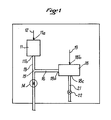
- the resuscitator installed in the hyperbaric chamber 10 comprises a pneumatic logic cell 11 determining the frequency of respiration, and the I / E ratio of the inspiration time to the expiration time.
- the cell 11 is provided at its inlet 11a with means 12 for supplying gas at a pressure of constant absolute value, coming from inside or outside the chamber 10, means being furthermore provided for keeping the 'inside the chamber the desired pressure, which, depending on the case, can range from 1 to 5 bar approximately.
- the exhaust pipe 13 at the outlet 11b of the cell leads out of the chamber 10, at atmospheric pressure under general conditions.
- a resistor 14 is mounted, such as a throttle.
- a bypass 16 connected to a control input 18a of a distributor 18.
- This distributor 18 is connected by an input 18b to a source 19 of gas which is breathable under pressure proportional to the pressure prevailing in the chamber.
- the distributor 18 is on the other hand connected to the respiratory mask by a line 21 connected to the outlet 18c. Line 21 is advantageously provided with an adjustment 22.
- the organs and expiration lines known in themselves are not shown.
- the device operates as follows. When there is no signal at the output 11b of the cell, no pressure, no flow, the pressure outside the cham bre (atmospheric pressure), prevails in lines 13 and 16. When a pressure signal is delivered at the outlet 11b of the cell, it prevails upstream of the resistance 14, and consequently in line 16 to the distributor 18 , higher pressure. The operation of the distributor 18 is therefore controlled by the pressure level present at its inlet 18a.
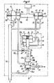
- FIG. 2 illustrates by way of nonlimiting example how the distributor, the logic cell 11 and the supplies 12 of gas at constant constant pressure gas and 19 in breathable gas can be produced under a pressure proportional to the pressure prevailing in the box .
- the distributor 18 is a distributor with an inlet 18b and two outlets 18c, 18e, one of which, unnecessary, is closed. It contains a piston 25, the first face 25a of which is exposed to the control pressure 18a. The second face 25b is biased by a spring 26 towards the position shown, in which the outlet 18c is closed.
- the end of the distributor 18, corresponding to the second face 25b of the piston, is placed in communication with atmospheric pressure by a pipe 27 connected, on one side to an outlet orifice 18d, and on the other to a manifold 30 in communication with the outside of chamber 10, that is to say with atmospheric pressure.
- This collector can receive the rejection of exhaled gases when the reviver has a "spill" device, which allows the exhalation of gases at atmospheric pressure.
- the outlet 18c is closed by the spring 26 acting on the face 25b of the piston. When pressure is exerted on the face 25a, the piston moves against the spring 26 and releases the outlet 18c.
- a logic pneumatic cell is a pneumatic device supplied continuously by pressurized gas and supplying a discontinuous pneumatic signal as an output, all or nothing defined by the frequency of the periods and the ratio signal time / no signal time.
- These devices of known type or resulting from the association of known pneumatic components, are essentially formed from bi-stable valves associated with pneumatic resistances and capacities according to the laws governing pneumatic oscillators.
- the cell shown is constituted by a flat box 33 separated into two parts 33a and 33b by a membrane 31. The supply of gas at constant absolute pressure is ensured by a pipe 32 opening into part 33b through the inlet 11a of the cell .
- a tube 35 forming a capacity, crosses the external wall of the part 33b and extends to the membrane 31 whose displacement, under the effect of the pressures prevailing in the parts 33a and 33b, and under the effect of 'a spring 36, closes or releases the inner end of the tube 35.
- the tube 35 and the part 33a are connected by a tube 38 provided with a restriction 39.
- the outlet (exhaust) 11b of the cell is located on the part outside of the tube 35.
- Such a cell is well known and it is not necessary to expand on its operation, which moreover results clearly from the structure described.
- the calibration of the spring and the restriction 39 make it possible to adjust the characteristics of the cell (frequency and duration of the opening periods).
- a source of pressurized gas 40 supplies breathable gas and is supplied from outside the chamber 10. This source discharges into a pipe 41 of the serving on one side a device 12 for supplying gas at a pressure of constant absolute value, and on the other a device 19 for breathing gas under a pressure proportional to the pressure prevailing in the chamber.
- the device 12 comprises a regulator constituted so as to close the passage between its inlet 12a and its outlet 12b, to which the supply 32 of the cell 11 is connected, when the pressure in the passage chamber 45 is greater than the absolute pressure chosen to supply the cell.
- a regulator constituted so as to close the passage between its inlet 12a and its outlet 12b, to which the supply 32 of the cell 11 is connected, when the pressure in the passage chamber 45 is greater than the absolute pressure chosen to supply the cell.
- a spring whose calibration determines the pressure.
- This dome 46 is waterproof and is directly connected by a pipe 49 to the manifold 30 opening to the atmosphere. The operation of such a regulator is well known.
- the device 19 is also of the expansion valve type, with a passage chamber 51, an inlet 19a and an outlet 19b, supplying the distributor 18 by a pipe 52. However, it comprises a double differential membrane 54, 55 delimiting an inert chamber 57 and a dome 58. The two membranes 54, 55 are connected by the rigid spacer of the valve and have different surfaces. The chamber 57 which they define together is connected to the manifold 30 at the reference atmospheric pressure by a pipe 60. The dome 58 contains a pressure spring 61 and is in communication with the hyperbaric chamber.
- Such a device 19 provides an insufflation flow at a pressure which is proportional to the pressure of the chamber to within a constant, the ratio of pressures being equal to the ratio of surfaces. If we call Pu the operating pressure, Pa the atmospheric pressure and Pc the pressure of the chamber, R the force of the spring at equilibrium and S and s the surfaces of the membranes, we have: is
Applications Claiming Priority (2)
| Application Number | Priority Date | Filing Date | Title |
|---|---|---|---|
| FR8217697A FR2534807A1 (fr) | 1982-10-22 | 1982-10-22 | Ranimateur hyperbare a commande pneumatique |
| FR8217697 | 1982-10-22 |
Publications (1)
| Publication Number | Publication Date |
|---|---|
| EP0107590A1 true EP0107590A1 (de) | 1984-05-02 |
Family
ID=9278500
Family Applications (1)
| Application Number | Title | Priority Date | Filing Date |
|---|---|---|---|
| EP19830402035 Withdrawn EP0107590A1 (de) | 1982-10-22 | 1983-10-20 | Überdruckwiederbelebungsgerät mit pneumatischer Regelung |
Country Status (2)
| Country | Link |
|---|---|
| EP (1) | EP0107590A1 (de) |
| FR (1) | FR2534807A1 (de) |
Cited By (1)
| Publication number | Priority date | Publication date | Assignee | Title |
|---|---|---|---|---|
| EP0164500A2 (de) * | 1984-06-14 | 1985-12-18 | Drägerwerk Aktiengesellschaft | Steuerbare Ventileinheit |
Citations (3)
| Publication number | Priority date | Publication date | Assignee | Title |
|---|---|---|---|---|
| GB1357635A (en) * | 1970-05-18 | 1974-06-26 | Medicor Muevek | Pneumatic pressure type respirator |
| US3820566A (en) * | 1971-09-07 | 1974-06-28 | Veriflo Corp | Ventilator |
| US3991790A (en) * | 1973-09-28 | 1976-11-16 | Sandoz, Inc. | Patient ventilator trigger circuit |
Family Cites Families (1)
| Publication number | Priority date | Publication date | Assignee | Title |
|---|---|---|---|---|
| US1357635A (en) * | 1919-04-15 | 1920-11-02 | Sparks D Henderson | Railway-rail |
-
1982
- 1982-10-22 FR FR8217697A patent/FR2534807A1/fr active Granted
-
1983
- 1983-10-20 EP EP19830402035 patent/EP0107590A1/de not_active Withdrawn
Patent Citations (3)
| Publication number | Priority date | Publication date | Assignee | Title |
|---|---|---|---|---|
| GB1357635A (en) * | 1970-05-18 | 1974-06-26 | Medicor Muevek | Pneumatic pressure type respirator |
| US3820566A (en) * | 1971-09-07 | 1974-06-28 | Veriflo Corp | Ventilator |
| US3991790A (en) * | 1973-09-28 | 1976-11-16 | Sandoz, Inc. | Patient ventilator trigger circuit |
Cited By (2)
| Publication number | Priority date | Publication date | Assignee | Title |
|---|---|---|---|---|
| EP0164500A2 (de) * | 1984-06-14 | 1985-12-18 | Drägerwerk Aktiengesellschaft | Steuerbare Ventileinheit |
| EP0164500A3 (en) * | 1984-06-14 | 1986-12-30 | Dragerwerk Aktiengesellschaft | Respiration system and controllable valve unit hereto |
Also Published As
| Publication number | Publication date |
|---|---|
| FR2534807B1 (de) | 1985-03-15 |
| FR2534807A1 (fr) | 1984-04-27 |
Similar Documents
| Publication | Publication Date | Title |
|---|---|---|
| US3783891A (en) | Balanced regulator second stage | |
| US4436090A (en) | Piston actuated, pilot valve operated breathing regulator | |
| FR2634652A1 (fr) | Valve respiratoire asservissable | |
| FR2633834A1 (fr) | Valve de commande pneumatique | |
| NO981325L (no) | Inhaleringsanordning | |
| EP0510040A1 (de) | Beatmungsgerät. | |
| BE675104A (de) | ||
| US3386458A (en) | Internally actuated combined oxygen pressure regulator and oxygenair dilution valves for respiratory apparatus | |
| EP0098193A2 (de) | Mischeinrichtung mit Strömungsmessern zum Abgeben eines Gemisches aus zwei Gasen in einem Verhältnis, das nicht unter einem bestimmten Wert sein kann | |
| WO1996015822B1 (en) | Resuscitator | |
| EP0025444B1 (de) | Verfahren und vorrichtungen zum regeln des partiellen sauerstoffdrucks der gasmischung des atmungskreislaufs eines tauchers | |
| EP0287461A1 (de) | Bedarfsabhängiger Regler für Atemgas | |
| EP0107590A1 (de) | Überdruckwiederbelebungsgerät mit pneumatischer Regelung | |
| FR2573658A1 (fr) | Dispositif de pression expiratoire positive | |
| US2893386A (en) | Gas demand equipment | |
| US3375839A (en) | Breathing oxygen mask inhalation and exhalation diaphragm valve unit | |
| CA1055110A (fr) | Dispositif automatique d'ouverture et de fermeture des orifices d'entree et de sortie de comburant d'une pile a combustible | |
| US3467136A (en) | Regulators of a gas required for breathing of the pneumatic valve type | |
| FR2789913A1 (fr) | Dispositif a venturi de melange d'au moins deux composants gazeux | |
| FR2559926A1 (fr) | Dispositif de separation de gaz du type a tamis moleculaire | |
| US3973712A (en) | Underwater welding | |
| FR2535082A1 (fr) | Appareil respiratoire de plongee en eau profonde | |
| FR2469183A1 (fr) | Regulateur a la demande pour installation respiratoire | |
| FR3080358A1 (fr) | Appareil respiratoire de plongee sous-marine a recyclage de gaz en circuit semi-ferme | |
| EP0255789B1 (de) | Atmungsapparat für Taucher |
Legal Events
| Date | Code | Title | Description |
|---|---|---|---|
| PUAI | Public reference made under article 153(3) epc to a published international application that has entered the european phase |
Free format text: ORIGINAL CODE: 0009012 |
|
| AK | Designated contracting states |
Kind code of ref document: A1 Designated state(s): AT BE CH DE FR GB IT LI LU NL SE |
|
| 17P | Request for examination filed |
Effective date: 19841004 |
|
| STAA | Information on the status of an ep patent application or granted ep patent |
Free format text: STATUS: THE APPLICATION HAS BEEN WITHDRAWN |
|
| 18W | Application withdrawn |
Withdrawal date: 19851109 |
|
| RIN1 | Information on inventor provided before grant (corrected) |
Inventor name: LE MASSON, YVES |