EP0107563A1 - Plant for the continuous casting of steel - Google Patents
Plant for the continuous casting of steel Download PDFInfo
- Publication number
- EP0107563A1 EP0107563A1 EP19830401961 EP83401961A EP0107563A1 EP 0107563 A1 EP0107563 A1 EP 0107563A1 EP 19830401961 EP19830401961 EP 19830401961 EP 83401961 A EP83401961 A EP 83401961A EP 0107563 A1 EP0107563 A1 EP 0107563A1
- Authority
- EP
- European Patent Office
- Prior art keywords
- continuous casting
- grids
- grid
- cell
- installation
- Prior art date
- Legal status (The legal status is an assumption and is not a legal conclusion. Google has not performed a legal analysis and makes no representation as to the accuracy of the status listed.)
- Withdrawn
Links
Images
Classifications
-
- B—PERFORMING OPERATIONS; TRANSPORTING
- B22—CASTING; POWDER METALLURGY
- B22D—CASTING OF METALS; CASTING OF OTHER SUBSTANCES BY THE SAME PROCESSES OR DEVICES
- B22D11/00—Continuous casting of metals, i.e. casting in indefinite lengths
- B22D11/12—Accessories for subsequent treating or working cast stock in situ
- B22D11/128—Accessories for subsequent treating or working cast stock in situ for removing
- B22D11/1282—Vertical casting and curving the cast stock to the horizontal
-
- B—PERFORMING OPERATIONS; TRANSPORTING
- B22—CASTING; POWDER METALLURGY
- B22D—CASTING OF METALS; CASTING OF OTHER SUBSTANCES BY THE SAME PROCESSES OR DEVICES
- B22D11/00—Continuous casting of metals, i.e. casting in indefinite lengths
- B22D11/14—Plants for continuous casting
- B22D11/142—Plants for continuous casting for curved casting
Definitions
- the present invention relates to a continuous steel casting installation, more particularly intended for the casting of products with square or rectangular section, such as slabs, blooms or billets.
- the object of the invention is to improve the performance of this type of device in order to be able to increase the reliability of the installation as well as the casting speed.
- the installation according to the invention makes it possible in particular to obtain, with respect to known devices, better mechanical resistance of the grids, relatively in particular to expansion, as well as a better distribution of the cooling water and a better flow of this after spraying. It is characterized in that it is provided with grids for supporting the cast product each composed of straight prismatic elements fixed on a metal support with high inertia, said support being pierced with orifices intended for the passage of water sprayers, and said prismatic elements being assembled so as to leave free, for each cell, at least two passages for the discharge of cooling water between said cell and at least two adjacent cells.
- said cells are composed of squares or rectangles standing on one of their points.
- the mold has its serrated lower edge so as to be able to fit into the serration formed by the upper part of said grid device.
- the cast product 4 is supported at its exit from the mold by a wear grid 5 whose particular conformation is the main object of the invention, then, after a distance of one to two meters, by conventional rollers 6. Also very conventionally, the cast slab is cooled by spraying water jets from conventional sprayers 7 supplied by water supply ramps 8.
- the wear grid 5 consists of metallic elements 10 in the shape of a rectangle with a thickness of the order of 5 cm, these straight prismatic elements 10 being made of cast iron or steel and being screwed onto a support plate 9 d neighboring thickness, also of cast iron or steel, possibly cooled by circulation of water although this is not the case in the drawing, and being fixed to the frame of the installation by means not shown.
- the prismatic elements 10 are assembled three by three as shown in FIG. 2 so as to thus create cells 11 of rectangular section, standing on their point, and leaving on their lower side two passages 12 and 13, allowing the water to cooling to flow down as shown by the arrows in the drawing.
- the support sheet 9 is pierced with orifices 14, one per cell 11, and leaving room for the projection nozzles 7.
- the grid of the invention is shaped so that its upper part can be embedded in the serration 3 at the bottom of the mold 1.
- the grid 5 is arranged so as to leave with the serration 3 a space 15 in which water projectors 16 of rectangular and very elongated shape pass.
Landscapes
- Engineering & Computer Science (AREA)
- Mechanical Engineering (AREA)
- Continuous Casting (AREA)
Abstract
Description
La présente invention concerne une installation de coulée continue de l'acier, plus spécialement destinée à la coulée de produits à section carrée ou rectangulaire, tels que des brames, des blooms ou des billettes.The present invention relates to a continuous steel casting installation, more particularly intended for the casting of products with square or rectangular section, such as slabs, blooms or billets.
On connaît des installations de ce type dans lesquelles le produit coulé est soutenu immédiatement à sa sortie de la lingotière, par des grilles dont les alvéoles laissent un passage pour les buses de projection d'eau de refroidissement. Le brevet français 2.105.249 par exemple décrit une telle installation.Installations of this type are known in which the poured product is supported immediately upon leaving the ingot mold, by grids whose cells leave a passage for the cooling water spray nozzles. French patent 2,105,249 for example describes such an installation.
Le but de l'invention est d'améliorer les performances de ce genre de dispositif afin de pouvoir augmenter la fiabilité de l'installation ainsi que la vitesse de coulée. L'installation selon l'invention permet en particulier d'obtenir, par rapport aux dispositifs connus, une meilleure tenue mécanique des grilles, relativement en particulier aux dilatations, ainsi qu'une meilleure distribution de l'eau de refroidissement et un meilleur écoulement de celle-ci après pulvérisation. Elle est caractérisée en ce qu'elle est munie de grilles de support du produit coulé composées chacune d'éléments prismatiques droits fixés sur un support métallique à grande inertie, ledit support étant percé d'orifices destinés au passage des pulvérisateurs d'eau, et lesdits éléments prismatiques étant assemblés de manière à laisser libre, pour chaque alvéole, au moins deux passages pour l'évacuation de l'eau de refroidissement entre ladite alvéole et au moins deux alvéoles adjacentes.The object of the invention is to improve the performance of this type of device in order to be able to increase the reliability of the installation as well as the casting speed. The installation according to the invention makes it possible in particular to obtain, with respect to known devices, better mechanical resistance of the grids, relatively in particular to expansion, as well as a better distribution of the cooling water and a better flow of this after spraying. It is characterized in that it is provided with grids for supporting the cast product each composed of straight prismatic elements fixed on a metal support with high inertia, said support being pierced with orifices intended for the passage of water sprayers, and said prismatic elements being assembled so as to leave free, for each cell, at least two passages for the discharge of cooling water between said cell and at least two adjacent cells.
Avantageusement, lesdites alvéoles sont composées de carrés ou de rectangles debout sur une de leurs pointes. Avantageusement dans ce cas, la lingotière a son bord inférieur dentelé de manière à pouvoir s'encastrer dans la dentelure constituée par la partie supérieure dudit dispositif à grilles.Advantageously, said cells are composed of squares or rectangles standing on one of their points. Advantageously in this case, the mold has its serrated lower edge so as to be able to fit into the serration formed by the upper part of said grid device.
L'invention sera mieux comprise à l'aide de la description suivante d'un exemple préférentiel de réalisation, en référence aux dessins annexés dans lesquels :
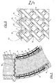
- la figure 1 est une vue en coupe latérale schématique de la portion de l'installation de coulée continue comportant les éléments de l'invention.
- la figure 2 est une vue en plan partielle d'un élément de grille de support équipant l'installation de la figure 1.
- Figure 1 is a schematic side sectional view of the portion of the continuous casting installation comprising the elements of the invention.
- FIG. 2 is a partial plan view of a support grid element fitted to the installation of FIG. 1.
On reconnaît sur la figure 1 la partie inférieure de la lingotière 1 refroidie en 2 par circulation d'eau. Conformément à un aspect optionnel mais avantageux de l'invention, le bord inférieur 3 de la lingotière est dentelé comme représenté sur le dessin.We recognize in Figure 1 the lower part of the lingo third 1 cooled in 2 by circulating water. According to an optional but advantageous aspect of the invention, the lower edge 3 of the mold is serrated as shown in the drawing.
De manière classique, le produit coulé 4 est soutenu à sa sortie de la lingotière par une grille d'usure 5 dont la conformation particulière est l'objet principal de l'invention, puis, après une distance d'un à deux mètres, par des rouleaux classiques 6. De manière très classique également, la brame coulée est refroidie par projection de jets d'eau issus de pulvérisateurs classiques 7 alimentés par des rampes d'amenée d'eau 8.Conventionally, the
On se reportera maintenant également à la figure 2 pour la description de la grille d'usure de l'invention. La grille d'usure 5 est constituée d'éléments métalliques 10 en forme de rectangle d'une épaisseur de l'ordre de 5 cm, ces éléments prismatiques 10 droits étant en fonte ou en acier et étant vissés sur une tôle de support 9 d'épaisseur voisine, également en fonte ou en acier, éventuellement refroidie par circulation d'eau bien que ce ne soit pas le cas sur le dessin, et étant fixée sur le châssis de l'installation par des moyens non représentés. Les éléments prismatiques 10 sont assemblés trois par trois comme représenté sur la figure 2 de façon à créer ainsi des alvéoles 11 de section rectangulaire, debout sur leur pointe, et laissant sur leur côté inférieur deux passages 12 et 13, permettant à l'eau de refroidissement de s'écouler vers le bas comme représenté par les flèches sur le dessin. Evidemment, la tôle de support 9 est percée d'orifices 14, un par alvéole 11, et laissant la place pour les buses de projection 7.Reference will now also be made to FIG. 2 for the description of the wear grid of the invention. The
Par ailleurs, la grille de l'invention est conformée de façon à ce que sa partie supérieure puisse s'encastrer dans la dentelure 3 du bas de la lingotière 1. La grille 5 est disposée de manière à laisser avec la dentelure 3 un espace 15 dans lequel passent des projecteurs d'eau 16 de forme rectangulaire et très allongée.Furthermore, the grid of the invention is shaped so that its upper part can be embedded in the serration 3 at the bottom of the
On remarquera qu'avec la disposition de l'invention, on obtient une grille de soutien permettant une excellente répartition des dilatations et le long de laquelle l'eau projetée par les pulvérisateurs sur la surface du produit coulé 4 peut s'écouler sans perturber les pulvérisateurs voisins pour être finalement rejetée à l'extérieur de la ligne.It will be noted that with the arrangement of the invention, a support grid is obtained allowing an excellent distribution of the expansions and along which the water projected by the sprayers on the surface of the
Claims (3)
caractérisée en ce que lesdites grilles sont composées chacune d'éléments prismatiques droits (10) fixés sur un support métallique à grande inertie (9), ledit support métallique étant percé d'orifices (14) destinés au passage des pulvérisateurs d'eau (7) et lesdits éléments prismatiques étant assemblés de manière à laisser libre, pour chaque alvéole (11) au moins deux passages (12, 13) pour l'évacuation de l'eau de refroidissement, lesdits passages faisant communiquer ladite alvéole avec au moins deux alvéoles adjacentes.1. Installation intended for the continuous casting of products with square or rectangular section, said installation being provided, at the outlet of the ingot mold (1) with grids (15) for supporting the product,
characterized in that said grids are each composed of straight prismatic elements (10) fixed on a metal support with high inertia (9), said metal support being pierced with orifices (14) intended for the passage of water sprayers (7 ) and said prismatic elements being assembled so as to leave free, for each cell (11) at least two passages (12, 13) for discharging the cooling water, said passages communicating said cell with at least two cells adjacent.
caractérisée en ce que le bord inférieur (3) de la lingotière associée est dentelé de manière à pouvoir s'encastrer dans la dentelure constituée par la partie supérieure dudit dispositif de support à grilles.2. Continuous casting installation according to claim 1, of the type according to which the cells of the grid are composed of rectangles standing on one of their points,
characterized in that the lower edge (3) of the associated ingot mold is serrated so as to be able to fit into the serration formed by the upper part of said grid support device.
Applications Claiming Priority (2)
| Application Number | Priority Date | Filing Date | Title |
|---|---|---|---|
| FR8216856A FR2534166A1 (en) | 1982-10-08 | 1982-10-08 | INSTALLATION OF CONTINUOUS CASTING OF STEEL |
| FR8216856 | 1982-10-08 |
Publications (1)
| Publication Number | Publication Date |
|---|---|
| EP0107563A1 true EP0107563A1 (en) | 1984-05-02 |
Family
ID=9278079
Family Applications (1)
| Application Number | Title | Priority Date | Filing Date |
|---|---|---|---|
| EP19830401961 Withdrawn EP0107563A1 (en) | 1982-10-08 | 1983-10-07 | Plant for the continuous casting of steel |
Country Status (2)
| Country | Link |
|---|---|
| EP (1) | EP0107563A1 (en) |
| FR (1) | FR2534166A1 (en) |
Cited By (2)
| Publication number | Priority date | Publication date | Assignee | Title |
|---|---|---|---|---|
| US4815519A (en) * | 1987-03-23 | 1989-03-28 | Dujardin Montbard Somenor Z. I. Lille-Seclin | Device for supporting and cooling a continuous casting emerging from a mold |
| DE19542180C1 (en) * | 1995-11-03 | 1997-04-03 | Mannesmann Ag | Method and device for guiding strands of a continuous caster |
Citations (7)
| Publication number | Priority date | Publication date | Assignee | Title |
|---|---|---|---|---|
| FR1118841A (en) * | 1955-01-03 | 1956-06-12 | Process and plant for metal casting | |
| FR2002994A1 (en) * | 1968-03-01 | 1969-11-07 | Olsson Ag Erik | PROCESS FOR SUPPORTING A CONTINUOUSLY CAST INGOT |
| FR2105249A1 (en) * | 1970-09-04 | 1972-04-28 | Concast Ag | |
| FR2125411A1 (en) * | 1971-02-11 | 1972-09-29 | Rossi Irving | |
| US3774671A (en) * | 1971-10-07 | 1973-11-27 | I Rossi | Continuous casting apparatus with strand support means |
| FR2314002A2 (en) * | 1975-06-13 | 1977-01-07 | Fives Cail Babcock | Continuous casting of steel slabs - using parallel row of bars, sepd. by coolant nozzles, to support and cool slab |
| EP0018350A1 (en) * | 1979-04-20 | 1980-10-29 | Max Burkhard | Continuous-casting plant, especially for producing slabs |
-
1982
- 1982-10-08 FR FR8216856A patent/FR2534166A1/en active Granted
-
1983
- 1983-10-07 EP EP19830401961 patent/EP0107563A1/en not_active Withdrawn
Patent Citations (7)
| Publication number | Priority date | Publication date | Assignee | Title |
|---|---|---|---|---|
| FR1118841A (en) * | 1955-01-03 | 1956-06-12 | Process and plant for metal casting | |
| FR2002994A1 (en) * | 1968-03-01 | 1969-11-07 | Olsson Ag Erik | PROCESS FOR SUPPORTING A CONTINUOUSLY CAST INGOT |
| FR2105249A1 (en) * | 1970-09-04 | 1972-04-28 | Concast Ag | |
| FR2125411A1 (en) * | 1971-02-11 | 1972-09-29 | Rossi Irving | |
| US3774671A (en) * | 1971-10-07 | 1973-11-27 | I Rossi | Continuous casting apparatus with strand support means |
| FR2314002A2 (en) * | 1975-06-13 | 1977-01-07 | Fives Cail Babcock | Continuous casting of steel slabs - using parallel row of bars, sepd. by coolant nozzles, to support and cool slab |
| EP0018350A1 (en) * | 1979-04-20 | 1980-10-29 | Max Burkhard | Continuous-casting plant, especially for producing slabs |
Cited By (2)
| Publication number | Priority date | Publication date | Assignee | Title |
|---|---|---|---|---|
| US4815519A (en) * | 1987-03-23 | 1989-03-28 | Dujardin Montbard Somenor Z. I. Lille-Seclin | Device for supporting and cooling a continuous casting emerging from a mold |
| DE19542180C1 (en) * | 1995-11-03 | 1997-04-03 | Mannesmann Ag | Method and device for guiding strands of a continuous caster |
Also Published As
| Publication number | Publication date |
|---|---|
| FR2534166B1 (en) | 1984-11-30 |
| FR2534166A1 (en) | 1984-04-13 |
Similar Documents
| Publication | Publication Date | Title |
|---|---|---|
| BE1000877A3 (en) | Grid cooler for cooling hot bulk material. | |
| FR2703041A1 (en) | Method and device for melting glass | |
| FR2777574A1 (en) | Electrolysis cell for production of aluminum by Hall-Heroult electrolysis process, incorporating a cooling system | |
| EP0107563A1 (en) | Plant for the continuous casting of steel | |
| FR2550974A1 (en) | DEVICE AND METHOD FOR CONTINUOUS CASTING OF METAL | |
| EP1157765B1 (en) | Water cooling system for continuous casting equipment | |
| TR199801645T2 (en) | Melting pot with tube changer, layer for changer | |
| US3700027A (en) | Continuous casting machine | |
| FI71245B (en) | METALL FORM | |
| US3572423A (en) | Cooling device for castings in continuous casting installations for heavy metals or alloys thereof,particularly steel | |
| US4501314A (en) | Casting support apparatus for continuous casting equipment | |
| KR20110126135A (en) | Casting nozzle for a horizontal continuous casting system | |
| EP0241445B1 (en) | Method and apparatus for cooling a continuously cast metal product | |
| EP0961648B1 (en) | Method for producing a filter bottom for water treatment | |
| US5027882A (en) | Direct chill casting mould | |
| US5740852A (en) | Conveyor belt for use in a continuous strip-casting device for the casting of metal strips | |
| EP0327526A1 (en) | Device for cooling a metal during casting | |
| JP2003136204A (en) | Continuous casting mold dealing with high heat flux | |
| FR2488166A1 (en) | ROLLER CAGE FOR CONTINUOUS CASTING OF BILLETTES WITH MULTIPLE INDIVIDUAL CASTING PATHS | |
| EP0130887B1 (en) | Supporting device for a cast product emerging from a continuous-casting mouldand method for adjusting the device | |
| US3596707A (en) | Apparatus for continuous vertical casting | |
| US4069862A (en) | Continuous casting mold with horizontal inlet | |
| CA2234432C (en) | Continuous casting metal ingot mould | |
| FR2584322A1 (en) | Device for assembling the sides of a continuous-casting ingot mould | |
| JPH0327714Y2 (en) |
Legal Events
| Date | Code | Title | Description |
|---|---|---|---|
| PUAI | Public reference made under article 153(3) epc to a published international application that has entered the european phase |
Free format text: ORIGINAL CODE: 0009012 |
|
| AK | Designated contracting states |
Designated state(s): AT BE DE GB IT LU NL SE |
|
| 17P | Request for examination filed |
Effective date: 19840702 |
|
| STAA | Information on the status of an ep patent application or granted ep patent |
Free format text: STATUS: THE APPLICATION IS DEEMED TO BE WITHDRAWN |
|
| 18D | Application deemed to be withdrawn |
Effective date: 19850716 |
|
| RIN1 | Information on inventor provided before grant (corrected) |
Inventor name: BARBE, JACQUES |