EP0107553A1 - Einrichtung zur automatischen Verarbeitung von Daten einer Karte, insbesondere von einer magnetischen und/oder elektronischen Karte - Google Patents
Einrichtung zur automatischen Verarbeitung von Daten einer Karte, insbesondere von einer magnetischen und/oder elektronischen Karte Download PDFInfo
- Publication number
- EP0107553A1 EP0107553A1 EP19830401943 EP83401943A EP0107553A1 EP 0107553 A1 EP0107553 A1 EP 0107553A1 EP 19830401943 EP19830401943 EP 19830401943 EP 83401943 A EP83401943 A EP 83401943A EP 0107553 A1 EP0107553 A1 EP 0107553A1
- Authority
- EP
- European Patent Office
- Prior art keywords
- card
- housing
- carriage
- mobile carriage
- spring
- Prior art date
- Legal status (The legal status is an assumption and is not a legal conclusion. Google has not performed a legal analysis and makes no representation as to the accuracy of the status listed.)
- Granted
Links
Images
Classifications
-
- G—PHYSICS
- G06—COMPUTING OR CALCULATING; COUNTING
- G06K—GRAPHICAL DATA READING; PRESENTATION OF DATA; RECORD CARRIERS; HANDLING RECORD CARRIERS
- G06K7/00—Methods or arrangements for sensing record carriers, e.g. for reading patterns
- G06K7/08—Methods or arrangements for sensing record carriers, e.g. for reading patterns by means detecting the change of an electrostatic or magnetic field, e.g. by detecting change of capacitance between electrodes
- G06K7/082—Methods or arrangements for sensing record carriers, e.g. for reading patterns by means detecting the change of an electrostatic or magnetic field, e.g. by detecting change of capacitance between electrodes using inductive or magnetic sensors
- G06K7/083—Methods or arrangements for sensing record carriers, e.g. for reading patterns by means detecting the change of an electrostatic or magnetic field, e.g. by detecting change of capacitance between electrodes using inductive or magnetic sensors inductive
- G06K7/084—Methods or arrangements for sensing record carriers, e.g. for reading patterns by means detecting the change of an electrostatic or magnetic field, e.g. by detecting change of capacitance between electrodes using inductive or magnetic sensors inductive sensing magnetic material by relative movement detecting flux changes without altering its magnetised state
Definitions
- the present invention relates to a device for automatically processing information for reading and / or writing on a card, in particular a magnetic card, for example of the credit card type, and / or an electronic card.
- the card is inserted by the user into a slot and is then conveyed by the device during the processing operations.
- the present invention relates to a simpler device where the card is kept in a stationary position during processing of the card and in which a locking device blocks the card in a fixed position removing the user from any possibility of remove it from the slot in which it was inserted during the entire transaction period.
- the recording and / or reading operations are then carried out by displacement of the corresponding magnetic heads.
- the treatment device is characterized in that it comprises a housing in a housing for receiving a card carrying information, a carriage movable relative to the housing and carrying at least one head intended for said treatment, a device for driving the mobile carriage, an automatic control device for moving the mobile carriage and processing the card, and a locking device controlled by the movement of the mobile carriage to block the card in the housing during processing.
- the device for driving the mobile carriage comprises a motor carried by the mobile carriage and a pulley in mechanical connection with the housing.
- the pulley can be associated with a tensioned cable carried by the housing and which makes at least one turn around the pulley, the rotation of the pulley then causing the moving carriage to move along the cable.
- the cable can be kept tensioned by means of a spring in order to ensure a constant tension while constituting a damping during starting and stopping of the engine.
- it is advantageous that the pulley is provided with a helical groove.
- the mobile carriage can carry at least one ball guide guided by a cylindrical axis integral with the housing, and a caster guided by a groove parallel to the cylindrical axis, formed in the housing.
- the carriage can carry a roller in contact with a cam which drives the locking device.
- the cam can be constituted by a curved profile flap actuating at least the locking device, which comprises for example at least one lug for blocking the card, and which is recalled by at least one first spring.
- the flap can be movable in rotation about a fixed axis relative to the housing.
- the locking device is actuated by the flap via a second spring of greater stiffness than the first return spring of the lug.
- the second spring can be constituted by a V-shaped leaf spring, the central part of which is taken around a stud fixed relative to the housing, the two branches of the V bearing respectively on the flap and on the lug.
- the locking device can be constituted by a movable L-shaped part, at the level of a first branch, around a second axis fixed relative to the housing, and have a second branch penetrating transversely into the housing.
- the mobile carriage can carry a clock track reading head in contact with a clock track secured to the housing.
- the automatic control device can be activated by a card presence detector, so as to ensure a processing cycle.
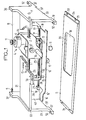
- the device comprises a housing 15 consisting of two side walls 20 having at its lower part recesses 37 having threads not shown and intended to allow the fixing of a lower plate 5 provided at each of its longitudinal ends of lugs 34 in which are provided notches 33 intended to receive fixing screws.
- Each of the side walls 20 is provided at its upper part with a groove 60.
- These grooves 60 receive a plate constituting a plate 21.
- the length of the grooves 60 is approximately equal to the width of the plate 21.
- the plate 21 is held in stop in the grooves 60 by any suitable means.
- the plate 21 and the grooves 60 can be dimensioned in such a way that the plate 21 is forced into the grooves 60.
- a mobile carriage designated by the general reference 4 is capable of moving on a carrying axis 1 fixed at each of its ends on the side walls 20. This movement takes place by means of ball guides 2 carried by the mobile carriage 4.
- the horizontal carriage of the movable carriage 4 is ensured during its displacement by a caster 22 rotating in a bearing integral with the carriage 4.
- the caster 22 moves in a parallelepiped groove whose axis is parallel to the axis 1 This groove is represented in FIG. 2 on the reference 48.
- a motor 6 is carried by a support 24 of the movable carriage and drives a pulley 7.
- a wire 8, stretched between the upper ends 36 and 37 of the lateral edges 20 makes at least one turn around the pulley 7.
- the pulley 7 advantageously has a groove helical.
- the tension of the wire 8 is ensured by a helical spring 9. Under these conditions, the actuation of the motor 6 causes the longitudinal movement of the mobile carriage along the axis 1, between the side walls 20.
- the magnetic heads 3 and 3 ' one for reading the card and the other for reading a clock track 35 arranged in a recess 36 in the lower plate 5, are mounted on the block 24.
- the clock track 3 ' only exists when the card must be encoded or re-encoded (see French patent application 81 04 330 filed on March 4, 1981 by the Applicant).
- other known devices for coding the movement of the mobile carriage 4 can be used.
- the side opposite to the rolled edge 17 is extended at one end by a curved profile 16 'itself extended by a plate 16.
- Locking lugs 13 freely sliding in a stirrup 26 carried by the lower face 28 of the plate 21 are in mechanical contact with the flap 12
- a caster 11 carried by the sleeve 10 is in contact with the plate 16 of the flap 12.
- the flap 12 is in fact kept in contact with the caster 11 under the action of its own weight which can alone suffice and of the return force of the spring 32. Under these conditions, the pins 13 are in the low position.
- a card is inserted into a slot 25 formed in the lower part of the plate 21 until it comes into abutment at 31 (figure 2).
- This slot is constituted by a recess 30 of the plate 21 and by a plate 27 fixed to the lower face 28 of the plate 21 and covering the recess 30.
- the presence of the magnetic card is detected by a device 14 disposed in the slot 25, which automatically controls the processing cycle.
- the mobile carriage is actuated and moves longitudinally along axis 1 (to the right in Figure 1).
- the caster 11 successively comes into contact with the curved profile 16 and then with the lower part of the flap 12, which has the effect of moving the pins 13 upwards.
- the upper end of the pins 13 then passes through bores made in the plate 27 and in the plate 21, and comes to lock the card in position for the entire duration of the reading and / or writing processing.
- Such processing can moreover implement several back and forth movements of the card during the transaction.
- Said device is dimensioned in such a way that the blocking of the card is effective over the entire processing range thereof by the head 3.
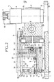
- FIG 2 we see the support 24 on which are fixed, in addition to the bracket 23, on the one hand two head support blocks 61 carrying the heads 3 and 3 'respectively, and on the other hand a bracket 41 on which the motor 6 is fixed.
- the block 24 further carries at its upper part a boss 51 carrying a detection head 52.
- the detection head 52 associated with corresponding marks carried by the lower part 29 of the plate 27, makes it possible to detecting the end-of-travel positions of the movable carriage 4.
- the bearing 42 of the caster 22 is fixed to the stirrup 23 by a screw 43, its positioning being determined by a spacer 42 '.
- the groove 48 parallel to the axis 1 is formed in the support 47 fixed by screws 46 to the lower part of the plate 21.
- the lower plate 27 has an opening 40 bordered by a cover 38 allowing the head 3 to read the or the card tracks arranged in the groove 25 while preventing the user from having access to the head 3.
- the pivots 13 are provided with a rounded lower part 53 which bears on the flap 12 and with a central part enlarged 49 serving as a stop for a spring 32 which is compressed between the central part 49 and the lower portion 29 of the plate 27.
- the upper end 54 of the pivot 13 is planar.
- the spring 32 ensures a return of the pivot 13 as well as of the flap 12 when the roller 11 is in contact with the plate 16.
- the carrier axis 1 is mounted on one of the side walls 20 (the one on the left for example).
- the boss 51 is then put in place with its detection system 52, and the stirrup 23 is fixed on the support 24.
- the mobile carriage is then engaged on the carrier axis 1.
- the plate 27 is assembled on the plate 21, as well as the support 47 (using the screws 46) on which the flap 12 has previously been mounted, after which the procedure is carried out. to the fixing of the stirrups 26 (on the plate 21) equipped with the pins 13 on which the springs 32 are mounted.
- the plate thus equipped is then engaged in the groove 60 of the side wall (left) ensuring the engagement of the roller 22 in the guide groove 48 and the correct positioning of the roller 11 on the flap 12.
- the engagement of the roller 22 in the groove 48 takes place when the head 3 is perpendicular to the opening 40.
- the wire 8 is then immobilized at points 36 and 37 after having made at least one revolution on the motor pulley 7.
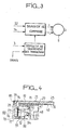
- a motor control device 6 receives signals from the presence detector 14, and from the limit switch 52, as well as control signals from a transaction processing device.
- the latter receives orders for the execution of the transaction, for example instructions given on a keyboard by the card holder, as well as the signals read by the head 3.
- the control device then sends towards the motor 6 control signals corresponding to the rotation of the motor in either direction (more or less). More specifically, during the introduction of a card 14 into the slot 25, the signal from the presence detector 14 causes the motor 6 to be started by the control device.
- the movable carriage 4 is driven longitudinally along the axis 1, towards the card, for example with a view to reading the latter for its identification.
- the transaction processing device will then send control signals to the control device under the action of part of the signals read by the head 3 and orders given for the transaction, for example using a keyboard of dialogue.
- the last order will be an order to return the carriage 4 to the rest position.
- a signal produced by the limit switch 52 will then represent a stop signal for the motor in the rest position.
- FIG. 4 represents a variant of the device for locking the card in the groove 25.
- a support 70 carries two axes 71 and 84 respectively.
- an L-shaped part 72 is mounted freely in rotation.
- the small branch 73 of the L has an edge 79 extending from its end 74 towards the large branch of the L and being able to extend to the latter.
- a helical spring 76 is hooked on the one hand to an axis 75 of the L-shaped part 72 and on the other hand to a flange 77 of a spring stopper 78 fixed to the lower part of the plate 21.
- the spring 76 serves as a return spring to the part 72.
- a V-shaped flat spring 80 is fixed by a central loop 83 to the axis 84 of the support 70. This axis 84 is located below of the axis 71.
- the lower branch 81 of the spring 80 bears on the flap 12 and the upper branch 82 bears on the lower part of the part 72.
- the spring 80 has a stiffness greater than that of the spring 76.
- the flap 12 is in the low position under the action of its own weight, which alone can suffice and of the return force of the spring 76 and the part 72 is practically no longer subjected to the action of the spring 80. It is therefore returned to the low position by the spring 76, which releases the end 74 of the part 72 from the slot 25 and allows the user to insert or remove his card .
- the flap 12 is in the high position.
- the spring 80 whose stiffness is greater than that of the spring 76 drives the part 72 upwards so as to ensure the blocking of the card.
- the end 74 of the part 72 is located at the level of a housing 85 of the plate 21.
- the card introduced into the slot 25 is pushed into abutment at 31 by the edge 79 in the form of a ramp of the small branch 73 of the L of the part 72. Since the part 72 is pushed upwards by the spring 80, it follows that the pressing of the card into abutment at 31 is ensured by an elastic force of determined intensity.
- the edge 79 of the short side 73 of the part 72 is capable of absorbing variations in width of the card while ensuring its abutment under the action of an elastic force.
- a ramp effect can be obtained by profiling the edge 79 of the small branch 73 of the L in contact with the card so that it is not perpendicular to the card when the latter is locked in abutment.
- the invention is not limited to the embodiments described.
- the fact that the card is kept fixed during the transaction can be used to make the device usable with electronic cards.
- a suitable connector can be placed at the level of the slot 25 so that the electronic card is inserted therein when the latter is placed in order to read its magnetic strip.
Landscapes
- Engineering & Computer Science (AREA)
- Artificial Intelligence (AREA)
- Computer Vision & Pattern Recognition (AREA)
- Physics & Mathematics (AREA)
- General Physics & Mathematics (AREA)
- Theoretical Computer Science (AREA)
- Conveying Record Carriers (AREA)
Applications Claiming Priority (2)
| Application Number | Priority Date | Filing Date | Title |
|---|---|---|---|
| FR8217295A FR2534713B1 (fr) | 1982-10-15 | 1982-10-15 | Dispositif de traitement automatique des informations d'une carte, notamment d'une carte magnetique et/ou electronique |
| FR8217295 | 1982-10-15 |
Publications (2)
| Publication Number | Publication Date |
|---|---|
| EP0107553A1 true EP0107553A1 (de) | 1984-05-02 |
| EP0107553B1 EP0107553B1 (de) | 1987-02-11 |
Family
ID=9278311
Family Applications (1)
| Application Number | Title | Priority Date | Filing Date |
|---|---|---|---|
| EP19830401943 Expired EP0107553B1 (de) | 1982-10-15 | 1983-10-04 | Einrichtung zur automatischen Verarbeitung von Daten einer Karte, insbesondere von einer magnetischen und/oder elektronischen Karte |
Country Status (4)
| Country | Link |
|---|---|
| EP (1) | EP0107553B1 (de) |
| DE (1) | DE3369805D1 (de) |
| ES (1) | ES526469A0 (de) |
| FR (1) | FR2534713B1 (de) |
Citations (3)
| Publication number | Priority date | Publication date | Assignee | Title |
|---|---|---|---|---|
| US3555246A (en) * | 1964-01-14 | 1971-01-12 | Jerome H Lemelson | Document reading apparatus |
| FR2356206A1 (fr) * | 1976-06-25 | 1978-01-20 | Siemens Ag | Appareil de lecture ou d'ecriture pour cartes pourvues d'un support de donnees magnetique |
| US4151564A (en) * | 1977-12-02 | 1979-04-24 | Burroughs Corporation | Modular, semiautomatic credit card reader/writer apparatus |
-
1982
- 1982-10-15 FR FR8217295A patent/FR2534713B1/fr not_active Expired
-
1983
- 1983-10-04 DE DE8383401943T patent/DE3369805D1/de not_active Expired
- 1983-10-04 EP EP19830401943 patent/EP0107553B1/de not_active Expired
- 1983-10-14 ES ES526469A patent/ES526469A0/es active Granted
Patent Citations (3)
| Publication number | Priority date | Publication date | Assignee | Title |
|---|---|---|---|---|
| US3555246A (en) * | 1964-01-14 | 1971-01-12 | Jerome H Lemelson | Document reading apparatus |
| FR2356206A1 (fr) * | 1976-06-25 | 1978-01-20 | Siemens Ag | Appareil de lecture ou d'ecriture pour cartes pourvues d'un support de donnees magnetique |
| US4151564A (en) * | 1977-12-02 | 1979-04-24 | Burroughs Corporation | Modular, semiautomatic credit card reader/writer apparatus |
Also Published As
| Publication number | Publication date |
|---|---|
| ES8405976A1 (es) | 1984-06-16 |
| ES526469A0 (es) | 1984-06-16 |
| DE3369805D1 (en) | 1987-03-19 |
| FR2534713B1 (fr) | 1987-10-23 |
| FR2534713A1 (fr) | 1984-04-20 |
| EP0107553B1 (de) | 1987-02-11 |
Similar Documents
| Publication | Publication Date | Title |
|---|---|---|
| EP0218504B1 (de) | Verfahren zur Beschlagnahme einer Karte in einer kombinierten Abtasteinrichtung und kombinierte Abtasteinrichtung | |
| EP0215712B1 (de) | Lese- und Schreibeinrichtung für Identitätskarten | |
| CH649859A5 (fr) | Appareil d'enregistrement ou de lecture muni d'un dispositif d'insertion d'une cassette ou d'un disque. | |
| FR2565391A1 (fr) | Appareil d'enregistrement et/ou de reproduction selective et/ou successive de disques ou de cassettes du type changeur | |
| FR2623928A1 (fr) | Lecteur de cartes porteuses d'une information codee, notamment de cartes a circuit integre | |
| FR2530365A1 (fr) | Appareil de chargement d'une cassette a disque magnetique | |
| FR2508220A1 (fr) | Cartouche pour appareil d'enregistrement/reproduction d'informations | |
| FR2475775A1 (fr) | Dispositif d'enregistrement et/ou de reproduction a bande magnetique | |
| FR2522180A1 (fr) | Dispositif d'entrainement de disque | |
| FR2512248A1 (fr) | Adaptateur de cassette permettant de monter une cassette de petite taille dans un appareil prevu pour cassette de taille normale | |
| FR2548421A1 (fr) | Dispositif de nettoyage d'un appareil de lecture et/ou d'enregistrement | |
| EP0107553B1 (de) | Einrichtung zur automatischen Verarbeitung von Daten einer Karte, insbesondere von einer magnetischen und/oder elektronischen Karte | |
| FR2464533A1 (fr) | Appareil d'enregistrement a ruban tendu | |
| EP0112747B1 (de) | Einrichtung zum automatischen Bearbeiten einer Karte mit aufgezeichneten Daten | |
| FR2682845A1 (fr) | Appareil et procede d'entrainement de plateau d'un appareil combinant une camera et un enregistreur. | |
| FR2756496A1 (fr) | Appareil de grattage d'un support d'informations masquees | |
| BE1008042A3 (fr) | Dispositif de commande pour appareils d'enregistrement et/ou de lecture. | |
| EP0369978A2 (de) | Lade-, Entlade und Zentriervorrichtung für Platten mit verschiedenen Grössen | |
| WO1993025977A1 (fr) | Recepteur de carte permettant l'ejection d'une carte cassee et lecteur de carte l'utilisant | |
| FR2501401A1 (fr) | Procede d'enregistrement et/ou de lecture d'informations sur un support magnetique et dispositif de mise en oeuvre | |
| CH332874A (fr) | Mécanisme d'entraînement du support de sons pour appareil enregistreur et reproducteur de sons | |
| FR2494477A1 (fr) | Dispositif de mise hors position operative de la cassette dans les appareils d'enregistrement ou de reproduction de bandes magnetiques contenues dans des cassettes | |
| FR2458870A1 (fr) | Mecanisme de chargement et de dechargement de cassette pour un enregistreur sur bande magnetique | |
| EP0881346A1 (de) | Antriebsvorrichtung zur Verriegelung und Entriegelung eines bedingt betätigbaren Schlosses | |
| EP0369859A1 (de) | Verfahren zum spielfreien Antrieb einer magnetischen Bandkassette |
Legal Events
| Date | Code | Title | Description |
|---|---|---|---|
| PUAI | Public reference made under article 153(3) epc to a published international application that has entered the european phase |
Free format text: ORIGINAL CODE: 0009012 |
|
| AK | Designated contracting states |
Designated state(s): BE DE IT NL SE |
|
| 17P | Request for examination filed |
Effective date: 19840614 |
|
| RAP1 | Party data changed (applicant data changed or rights of an application transferred) |
Owner name: L.C.C.-C.I.C.E. - COMPAGNIE EUROPEENNE DE COMPOSAN |
|
| RAP1 | Party data changed (applicant data changed or rights of an application transferred) |
Owner name: COMPAGNIE EUROPEENNE DE COMPOSANTS ELECTRONIQUES L |
|
| GRAA | (expected) grant |
Free format text: ORIGINAL CODE: 0009210 |
|
| AK | Designated contracting states |
Kind code of ref document: B1 Designated state(s): DE |
|
| REF | Corresponds to: |
Ref document number: 3369805 Country of ref document: DE Date of ref document: 19870319 |
|
| PLBE | No opposition filed within time limit |
Free format text: ORIGINAL CODE: 0009261 |
|
| STAA | Information on the status of an ep patent application or granted ep patent |
Free format text: STATUS: NO OPPOSITION FILED WITHIN TIME LIMIT |
|
| 26N | No opposition filed | ||
| BERE | Be: lapsed |
Owner name: COMPAGNIE EUROPEENNE DE COMPOSANTS ELECTRONIQUES L Effective date: 19871031 |
|
| PGFP | Annual fee paid to national office [announced via postgrant information from national office to epo] |
Ref country code: DE Payment date: 19900922 Year of fee payment: 8 |
|
| PG25 | Lapsed in a contracting state [announced via postgrant information from national office to epo] |
Ref country code: DE Effective date: 19920701 |