EP0107548B1 - Durch einen Motor betätigte Belade- und Entladevorrichtung - Google Patents
Durch einen Motor betätigte Belade- und Entladevorrichtung Download PDFInfo
- Publication number
- EP0107548B1 EP0107548B1 EP19830401893 EP83401893A EP0107548B1 EP 0107548 B1 EP0107548 B1 EP 0107548B1 EP 19830401893 EP19830401893 EP 19830401893 EP 83401893 A EP83401893 A EP 83401893A EP 0107548 B1 EP0107548 B1 EP 0107548B1
- Authority
- EP
- European Patent Office
- Prior art keywords
- carriage
- extractor
- pivoting
- pulley
- slide
- Prior art date
- Legal status (The legal status is an assumption and is not a legal conclusion. Google has not performed a legal analysis and makes no representation as to the accuracy of the status listed.)
- Expired
Links
- 238000005096 rolling process Methods 0.000 claims description 2
- 238000006243 chemical reaction Methods 0.000 description 1
- 238000006073 displacement reaction Methods 0.000 description 1
- 238000004519 manufacturing process Methods 0.000 description 1
Images

Classifications
-
- B—PERFORMING OPERATIONS; TRANSPORTING
- B21—MECHANICAL METAL-WORKING WITHOUT ESSENTIALLY REMOVING MATERIAL; PUNCHING METAL
- B21D—WORKING OR PROCESSING OF SHEET METAL OR METAL TUBES, RODS OR PROFILES WITHOUT ESSENTIALLY REMOVING MATERIAL; PUNCHING METAL
- B21D43/00—Feeding, positioning or storing devices combined with, or arranged in, or specially adapted for use in connection with, apparatus for working or processing sheet metal, metal tubes or metal profiles; Associations therewith of cutting devices
- B21D43/02—Advancing work in relation to the stroke of the die or tool
- B21D43/04—Advancing work in relation to the stroke of the die or tool by means in mechanical engagement with the work
- B21D43/10—Advancing work in relation to the stroke of the die or tool by means in mechanical engagement with the work by grippers
- B21D43/105—Manipulators, i.e. mechanical arms carrying a gripper element having several degrees of freedom
Definitions
- the present invention relates to coin extractor loaders comprising a carriage movable horizontally along a fixed frame, and a slide which is movable vertically relative to the carriage and carries a support provided with gripping means suitable for gripping a part.
- These extractor loaders are used to move parts, such as tubes, for example from one press to another for stamping operations.
- extractor loaders with a single motor which comprise an element pivotally mounted on the carriage and connected to the slide so that a pivoting of the element causes this slide to move relative to the carriage, means for preventing the element to pivot when the carriage is in the central part of its stroke, and a motor which is fixedly mounted on the frame and is connected to the carriage thus ensuring a horizontal movement of this carriage, as well as to the pivoting element so to ensure a vertical displacement of the slide when the element can pivot, (see for example FR-A 1 397 689 and FR-A 2 439 068).
- the present invention relates to an extractor loader of the above type, the production of which is particularly simple.
- the extractor loader is characterized in that the pivoting element consists of a pulley framed by two toothed wheels and integral with these wheels, in that a toothed belt has one of its ends wound on at least a half-circumference on the pulley when the carriage moves horizontally, being fixed to the rim of this pulley, and at its other end connected to two chains crossing the first end of the belt and arranged on either side of that -this, in that these chains are wound on the toothed wheels at least half a circumference when the carriage moves horizontally, and in that the traction element constituted by the toothed belt and the chains passes over an element d drive connected to the motor and to a return element.
- the pulley-cogwheel assembly can be connected to the slider by a crank whose axis is integral in rotation with this assembly and which is articulated on one end of a connecting rod whose other end is articulated on the slider .
- the means for preventing said element from pivoting can comprise a lever integral in rotation with this pivoting element and carrying rollers rolling on a fixed horizontal rail, the latter carrying at the desired location, or at each desired location, a cam with which the rollers cooperate by allowing the lever to pivot.
- the lever can for example carry at least three rollers, one of which is located in the axis of the pivoting element while the other two are provided at the ends of the lever, the cam having a central groove and two grooves in an arc in which the first roller and the other two can engage respectively.
- the lever may have a T-shape, its central branch carrying at its end a fourth roller capable of engaging in a groove in an arc of a circle of the cam, which is coaxial with the other two grooves in an arc of a circle. This roller allows the lever to resist the force exerted by the traction element of the pivoting part when the first three rollers are in the vertical position.
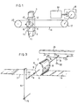
- the extractor loader comprises a fixed frame 1 on which a carriage 2 is mounted to move horizontally.
- the carriage carries support rollers 3a and holding 3b, of horizontal axis, which roll on a rail 4, and lateral guide rollers 5, of vertical axis, which roll on the rail 4 and on a rail 6, the rails 4 and 6 being integral with the frame 1.
- the carriage 2 can move vertically a slide 7 which is guided by rollers 34 and carries a support not shown and provided with gripping means for gripping a part to shift.
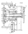
- An axis 8 is rotatably mounted in the carriage 2 by means of bearings 9. On this axis is keyed a pulley 10 on either side of which are fixed toothed wheels 11.
- the axis 8 is integral with a crank 12 articulated at 13 to a connecting rod 14, the foot of which is articulated at 15 on the slide 7.
- a toothed belt 16 passes over a drive pulley 17 whose axis is connected by a bevel gear 18 to a drive motor 19; it also passes over a return pulley 20.
- the upper strand of this belt passes directly from the drive pulley 17 to the return pulley 20.
- One end of the lower strand is wound on the pulley 10 over approximately 180 ° as indicated in ABC in Figure 3, and is fixed in C on the rim of this pulley.
- the other end of this lower strand is extended by two lateral chains 21 which pass over the toothed wheels 11, following the path ADC, and are fixed to these wheels on the same generator C of the pulley 10.
- the end of the axis 8 opposite the crank 12 carries a roller 22 and is integral with a lever 23 which carries at its ends two rollers 24 and 25, the axes of the rollers 22, 24 and 25 being located in the same plan. These rollers roll on a horizontal rail 26 fixed to the frame 1.
- the rail 26 carries a cam 27.
- This cam has a horizontal groove 28 and two arcuate grooves 29 and 30 which are directed one upwards and the other downwards. These grooves are connected to the groove 28 in places separated from each other by a distance equal to that separating the axes of the rollers 24 and 25.
- the lever 23 is integral with a lever 31 which is perpendicular thereto and carries a roller 32.
- the cam 27 has a groove 33 concentric with the grooves 29 and 30 and disposed symmetrically with respect to the groove 28. It is arranged so that the roller 32 is engaged therein when the rollers 24 and 25 are engaged in the grooves 29 and 30.
- the rollers 22, 24 and 25 and the rail 26 constitute a locking device which normally prevents the axis 8 from pivoting.
- the motor 19 rotates by driving the belt 16
- the torque exerted on the pulley 10 is canceled by the reaction of the rail on the rollers 22, 24 and 25 and the force is transmitted to the axis of the pulley 10 which drives the carriage 2 in translation, on guide rails 4 and 6.
- rollers 22, 24 and 25 respectively engage in the grooves 28, 29 and 30.
- the axis 8 can therefore pivot, while continuing to advance, and the crank 12 causes the slide 7 to move vertically. relative to the carriage 2.
- the roller 32 engages in the groove 33 and balances the force of the belt 16 on the pulley 10 when the lever 23 is in the vertical position.
Landscapes
- Engineering & Computer Science (AREA)
- Mechanical Engineering (AREA)
- Manipulator (AREA)
- Reciprocating Conveyors (AREA)
Claims (6)
Applications Claiming Priority (2)
| Application Number | Priority Date | Filing Date | Title |
|---|---|---|---|
| FR8216572A FR2533484B1 (fr) | 1982-09-28 | 1982-09-28 | Chargeur extracteur de pieces a un seul moteur asservi |
| FR8216572 | 1982-09-28 |
Publications (2)
| Publication Number | Publication Date |
|---|---|
| EP0107548A1 EP0107548A1 (de) | 1984-05-02 |
| EP0107548B1 true EP0107548B1 (de) | 1986-06-04 |
Family
ID=9277925
Family Applications (1)
| Application Number | Title | Priority Date | Filing Date |
|---|---|---|---|
| EP19830401893 Expired EP0107548B1 (de) | 1982-09-28 | 1983-09-27 | Durch einen Motor betätigte Belade- und Entladevorrichtung |
Country Status (3)
| Country | Link |
|---|---|
| EP (1) | EP0107548B1 (de) |
| DE (1) | DE3363945D1 (de) |
| FR (1) | FR2533484B1 (de) |
Families Citing this family (1)
| Publication number | Priority date | Publication date | Assignee | Title |
|---|---|---|---|---|
| CN106041611A (zh) * | 2016-08-24 | 2016-10-26 | 苏州亘富机械科技有限公司 | 一种用于数控机床生产零件的输送装置底架 |
Family Cites Families (4)
| Publication number | Priority date | Publication date | Assignee | Title |
|---|---|---|---|---|
| FR1397689A (fr) * | 1964-05-28 | 1965-04-30 | Us Industries Inc | Appareil destiné à déplacer une pièce à usiner entre des postes de travail |
| IT990272B (it) * | 1973-08-17 | 1975-06-20 | Fmi Mecfond Aziende Mecc | Dispositivo automatico di trasferi mento di oggetti in lavorazione tra due macchine operatrici |
| SE419303B (sv) * | 1978-10-19 | 1981-07-27 | Volvo Ab | Anordning for att overfora en rorelse i ett plan till en rorelse i ett deremot i huvudsak vinkelrett plan |
| FR2440270A1 (fr) * | 1978-11-02 | 1980-05-30 | Polymatic Sa | Automate, notamment pour les chargements sur presses |
-
1982
- 1982-09-28 FR FR8216572A patent/FR2533484B1/fr not_active Expired
-
1983
- 1983-09-27 DE DE8383401893T patent/DE3363945D1/de not_active Expired
- 1983-09-27 EP EP19830401893 patent/EP0107548B1/de not_active Expired
Also Published As
| Publication number | Publication date |
|---|---|
| FR2533484A1 (fr) | 1984-03-30 |
| EP0107548A1 (de) | 1984-05-02 |
| DE3363945D1 (en) | 1986-07-10 |
| FR2533484B1 (fr) | 1985-07-12 |
Similar Documents
| Publication | Publication Date | Title |
|---|---|---|
| FR2472426A1 (de) | ||
| FR2835034A1 (fr) | Dispositif de decharge d'efforts pour chaines porte-cables | |
| FR2641487A1 (fr) | Vehicule porteur a outil pour l'inspection et/ou la maintenance des trous de goujons de la bride porteuse du couvercle d'une cuve ou similaire | |
| EP0107548B1 (de) | Durch einen Motor betätigte Belade- und Entladevorrichtung | |
| FR2473445A1 (fr) | Installation de transport a angle droit et vehicule pour une telle installation | |
| FR2463003A1 (fr) | Perfectionnements aux machines de serigraphie concernant la monture porte-objets et son mouvement relatif par rapport a l'ecran | |
| FR2614666A1 (fr) | Derailleur arriere bicyclette, dont l'element de transmission de chaine est monte coulissant par rapport au cadre | |
| FR2727075A1 (fr) | Dispositif roulant de banderolage helicoidal non automoteur a support de bobine mobile verticalement | |
| EP0015215B2 (de) | Lader oder Auszieher von Stücken | |
| FR2541257A1 (fr) | Dispositif tendeur pour le transport de matieres en forme de bande | |
| EP0892758A1 (de) | Vorrichtung zum ziehen und drucken von einer last in eine gewisse ebene | |
| FR2551410A1 (fr) | Wagon de marchandises couvert a parois laterales constituees chacune d'au moins deux elements de paroi mobiles | |
| EP0156658A1 (de) | Riemengetriebe und Holzbearbeitungsmaschine mit demselben arbeitend | |
| WO2019145611A1 (fr) | Machine tronçonneuse de rails d'une voie de chemin de fer | |
| CH367957A (fr) | Grue à mât relevable | |
| EP0491631B1 (de) | Fördereinrichtung, mit Seitenführungseinrichtung mit Synchronantrieb | |
| CH682500A5 (fr) | Installation de levage auxiliaire de voie ferrée. | |
| EP0125189A1 (de) | Beladevorrichtung für Pressen | |
| FR2659261A1 (fr) | Actionneur reproducteur de deplacement et manipulateur equipe d'un tel dispositif. | |
| BE1004004A6 (fr) | Porte de garage. | |
| FR2523566A1 (fr) | Nacelle a deplacement lateral par rapport a un plateau support par exemple de chariot elevateur | |
| EP0002092A1 (de) | Gemüseschneidemaschine | |
| EP0612574B1 (de) | Stangenführung mit mehreren Antrieben | |
| CA1150597A (fr) | Dispositif d'abattage d'arbres | |
| FR2621517A1 (fr) | Poignet de robot pour le serrage et l'emmanchement de raccords en elastomere |
Legal Events
| Date | Code | Title | Description |
|---|---|---|---|
| PUAI | Public reference made under article 153(3) epc to a published international application that has entered the european phase |
Free format text: ORIGINAL CODE: 0009012 |
|
| AK | Designated contracting states |
Designated state(s): DE GB IT |
|
| 17P | Request for examination filed |
Effective date: 19840514 |
|
| ITF | It: translation for a ep patent filed | ||
| GRAA | (expected) grant |
Free format text: ORIGINAL CODE: 0009210 |
|
| AK | Designated contracting states |
Kind code of ref document: B1 Designated state(s): DE GB IT |
|
| REF | Corresponds to: |
Ref document number: 3363945 Country of ref document: DE Date of ref document: 19860710 |
|
| ITPR | It: changes in ownership of a european patent |
Owner name: OFFERTA DI LICENZA AL PUBBLICO |
|
| REG | Reference to a national code |
Ref country code: GB Ref legal event code: 746 |
|
| PLBE | No opposition filed within time limit |
Free format text: ORIGINAL CODE: 0009261 |
|
| STAA | Information on the status of an ep patent application or granted ep patent |
Free format text: STATUS: NO OPPOSITION FILED WITHIN TIME LIMIT |
|
| 26N | No opposition filed | ||
| PGFP | Annual fee paid to national office [announced via postgrant information from national office to epo] |
Ref country code: GB Payment date: 19910913 Year of fee payment: 9 |
|
| PGFP | Annual fee paid to national office [announced via postgrant information from national office to epo] |
Ref country code: DE Payment date: 19911114 Year of fee payment: 9 |
|
| PG25 | Lapsed in a contracting state [announced via postgrant information from national office to epo] |
Ref country code: GB Effective date: 19920927 |
|
| GBPC | Gb: european patent ceased through non-payment of renewal fee |
Effective date: 19920927 |
|
| PG25 | Lapsed in a contracting state [announced via postgrant information from national office to epo] |
Ref country code: DE Effective date: 19930602 |