EP0107527B1 - Device of the boiler-type using a solid-liquid suspension of the coal-water-type as fuel - Google Patents
Device of the boiler-type using a solid-liquid suspension of the coal-water-type as fuel Download PDFInfo
- Publication number
- EP0107527B1 EP0107527B1 EP83401755A EP83401755A EP0107527B1 EP 0107527 B1 EP0107527 B1 EP 0107527B1 EP 83401755 A EP83401755 A EP 83401755A EP 83401755 A EP83401755 A EP 83401755A EP 0107527 B1 EP0107527 B1 EP 0107527B1
- Authority
- EP
- European Patent Office
- Prior art keywords
- zone
- combustion
- fuel
- fluid
- solidification
- Prior art date
- Legal status (The legal status is an assumption and is not a legal conclusion. Google has not performed a legal analysis and makes no representation as to the accuracy of the status listed.)
- Expired
Links
Images
Classifications
-
- F—MECHANICAL ENGINEERING; LIGHTING; HEATING; WEAPONS; BLASTING
- F23—COMBUSTION APPARATUS; COMBUSTION PROCESSES
- F23C—METHODS OR APPARATUS FOR COMBUSTION USING FLUID FUEL OR SOLID FUEL SUSPENDED IN A CARRIER GAS OR AIR
- F23C99/00—Subject-matter not provided for in other groups of this subclass
-
- F—MECHANICAL ENGINEERING; LIGHTING; HEATING; WEAPONS; BLASTING
- F22—STEAM GENERATION
- F22B—METHODS OF STEAM GENERATION; STEAM BOILERS
- F22B21/00—Water-tube boilers of vertical or steeply-inclined type, i.e. the water-tube sets being arranged vertically or substantially vertically
- F22B21/34—Water-tube boilers of vertical or steeply-inclined type, i.e. the water-tube sets being arranged vertically or substantially vertically built-up from water tubes grouped in panel form surrounding the combustion chamber, i.e. radiation boilers
- F22B21/341—Vertical radiation boilers with combustion in the lower part
- F22B21/343—Vertical radiation boilers with combustion in the lower part the vertical radiation combustion chamber being connected at its upper part to a sidewards convection chamber
-
- F—MECHANICAL ENGINEERING; LIGHTING; HEATING; WEAPONS; BLASTING
- F23—COMBUSTION APPARATUS; COMBUSTION PROCESSES
- F23G—CREMATION FURNACES; CONSUMING WASTE PRODUCTS BY COMBUSTION
- F23G7/00—Incinerators or other apparatus for consuming industrial waste, e.g. chemicals
- F23G7/001—Incinerators or other apparatus for consuming industrial waste, e.g. chemicals for sludges or waste products from water treatment installations
Definitions
- the invention relates to devices of the boiler type which overcome most of the drawbacks mentioned above.
- the cylindrical combustion zone is equipped with a single multi-fluid type burner attached to the fixed end of the cylinder opposite the solidification zone and whose axis coincides with that of the combustion zone.
- a pumping system adapted to the fuel used (solid-liquid suspension) is used to introduce said fuel into the burner which also receives the auxiliary spraying gaseous fluid as well as the combustion air.
- the injection of all the active fluids into the hearth that constitutes the combustion zone is necessarily axial.
- the combustion zone is highly insulated by means of refractory products forming a radiant hot wall held in place by a metal casing.
- the spraying mentioned above is carried out at an effective pressure generally between 0.5 and 2 bars.
- the combustion zone is of elongated cylindrical shape, that is to say its length (L) will be at least equal to 3.25 times the inside diameter (D) of the cylinder.
- this zone In order to allow satisfactory evacuation of the slag which generally forms in the liquid state in this combustion zone, it will be inclined to the horizontal by an angle between 2 and 8 °. In addition, this zone will be rotated at a slow speed of the order of 1 to 5 revolutions per minute by means of a conventional roller or chain drive system.
- This solidification zone will have a volume generally between 10 and 15 times the volume of the combustion zone. It will advantageously take the form of a rectangular parallelepiped whose depth (P) will be at least equal to (L) length of the area of combustion, a width (1) at least equal to 2.25 D and a height (H) at least equal to 4 D.
- This solidification zone comprises on its side walls, constituted by a refractory insulating material held in place by a metallic envelope, cold tubes containing the pressurized fluid to be heated by radiation.
- it has in its lower part a hopper for recovering the slag from the combustion zone and the ash from the solidification zone.
- a horizontal convection zone equipped with a bundle of exchanger tubes operating by convection, and hoppers for recovering the dust present.
- this convectian zone can be arranged vertically so that the fumes flow from top to bottom, the main thing being that the gas stream is subjected to a significant change in direction.
- the solid-liquid suspension used as fuel in the device of the invention could for example be a mixture of finely ground coal, that is to say of which the particles will generally have a diameter of less than 100 microns and water or any other suitable liquid such as animal or vegetable oils, alcohols or fuels.
- the content of the mixture in liquid is preferably between 30 and 50% (weight).
- the combustion zone (5) is supplied with solid-liquid suspension via the line (1).
- Lines (2) and (3) lead the spray air and the combustion air respectively to the multi-fluid burner (4).
- This burner (4) is arranged on the fixed front wall (6) of the zone (5).
- the walls of this area are made of refractories (7) with a thickness of about 350 mm, held in place by the metallic outer casing (8).
- the area (5) inclined at an angle a of 3.5 ° to the horizontal is rotated by means of a system comprising a drive roller (9) and a support roller (10) on which the raceways (11). ).
- the zone (5) opens onto a solidification zone (12), taking the form of a rectangular parallelepiped.
- the inside of the walls of the zone (12) is lined with tubes (13) intended for heat exchange by radiation, said walls being made of an insulating refractory lining inside (14) of approximately 100 mm thickness maintained in placed by a metal casing (15).
- a hopper (16) intended to collect the slag and the ash.
- the walls of the hopper are made in a similar way to that of the heat exchange part of the zone (12).
- the zone (12) opens onto a convection zone (17) arranged perpendicular to the zone (12).
- This zone (17) is equipped with a battery of tubes (18) intended for heat exchange by convection.
- Lines (19) collect the steam-water emulsion produced by both the tubes (13) and the tubes (18) to direct it to the separator flask (20).
- the zone (17) is equipped at its lower part with hoppers (21) for the recovery of dust conveyed by the gas flow and possible deposits on the tubes (18), detached by means of a conventional blowing system not shown.
- the walls of the zone (17) consist of an insulating refractory (22) with a thickness of approximately 50 mm held in place by the envelope (23).
- the device of the invention described above is implemented according to the process described below with a coal-water suspension as fuel.
- This suspension consists of a weight mixture of 40% water, 60% carbon. This carbon was finely ground in an aqueous medium so as to obtain a particle size centered on 35 microns with a maximum of 100 microns. The viscosity of the mixture is reduced by adding an appropriate surfactant.
- the fuel is introduced by volumetric pumping into the burner, the latter being supplied separately with compressed air sprayed at 0.7 bar effective and with combustion air.
- the spray is injected into the axis of the combustion zone, the design of which allows the total combustion of the coal contained in the suspension within this zone itself with a combustion rate reaching 600 therms per m3 of combustion zone.
- the ignition of the fuel is ensured automatically by the temperature level prevailing in the zone preheated to 1100 ° C with conventional fuel. Therefore the temperature in steady state is of the order of 1400 ° C.
- the thermal load is modulated as required by direct action on the supply volumetric pump. The flexibility thus obtained allows an instantaneous variation of the calorific flow in the proportions of 1/5 to 5/5.
- the ash contained in the coal is in the liquid state in fine suspension in the combustion gases. A fraction of these particles is deposited in contact with the refractory walls on which they flow by gravity. Their evacuation is ensured by the conjunction of the inclination of the zone on the horizontal and its slow rotation.
- the hot gases (around 1400 ° C) produced in the combustion zone penetrate into the solidification zone.
- the gases in this zone cool down by radiation towards the cold walls lined with tubes, which automatically causes the concomitant cooling of the fine ashy molten particles transported within the gas stream.
- the temperature of the gas goes from 1400 to 850 ° C approximately.
- the hopper located at the lower part of this zone receives on the one hand the molten ash and the concretions coming from the combustion zone and on the other hand those which could form on the part of the wall facing combustion, then detach.
- the gases from the solidification zone penetrate into the convection zone where they are cooled, to a temperature of approximately 250 ° C. in contact with the bundles of exchanger tubes. In this area a fraction of lice "Sieres deposits on the tubes where they are driven by a conventional method for blow molding.
- Hoppers arranged at the base receive the dust falling by gravity.
- the water-steam emulsion generated in the exchange beams of the solidification and convection zones is collected at the top and directed towards the separating flask.
- the gases from the convection zone are dusted in a conventional manner before being discharged to the chimney.
- the devices of the invention are particularly advantageous because they allow the use of coals of all kinds as liquid fuel under particularly favorable operating conditions, particularly in terms of handling, ash extraction, flexibility of operation. and security.
Landscapes
- Engineering & Computer Science (AREA)
- Chemical & Material Sciences (AREA)
- Combustion & Propulsion (AREA)
- Mechanical Engineering (AREA)
- General Engineering & Computer Science (AREA)
- Environmental & Geological Engineering (AREA)
- Water Supply & Treatment (AREA)
- Physics & Mathematics (AREA)
- Thermal Sciences (AREA)
- Liquid Carbonaceous Fuels (AREA)
Abstract
Description
La présente invention concerne des dispositifs de type chaudière permettant de réaliser la combustion de mélanges solides liquides, par exemple charbon-eau et de récupérer les calories produites - sous forme de fluides chauds sous pression. La combustion du charbon est habituellement réalisée selon les principales techniques suivantes:
- - sur grille, le charbon étant alors chargé dans la chambre de combustion en masse c'est-à-dire que les particules de charbon présentent des dimensions importantes (de l'ordre de quelques centimètres).
- - sous forme pulvérisée, le charbon étant finement broyé à des dimensions fines (quelques dizaines de microns) et entraîné par un jet d'air de pulvérisation.
- - en litfluidisé, le charbon étant alors broyé à des dimensions de l'ordre de quelques millimètres. Cette dernière technique, assez récente, peut présenter diverses variantes de réalisation au niveau du type de lit mis en oeuvre.
- - On a grid, the coal then being loaded into the mass combustion chamber, that is to say that the coal particles have large dimensions (of the order of a few centimeters).
- - in pulverized form, the carbon being finely ground to fine dimensions (a few tens of microns) and entrained by a jet of atomizing air.
- - in litfluidized, the carbon then being ground to dimensions of the order of a few millimeters. This latter technique, which is fairly recent, can present various variant embodiments in terms of the type of bed used.
Toutes ces techniques présentent de sérieux problèmes d'exploitation, décrassage, évacuation des scories et des cendres, dépoussiérage, organes de sécurité etc... et imposent souvent des contraintes importantes de mise en oeuvre quant au choix du charbon, de la granulométrie et de la conduite des unités.All these techniques present serious operating problems, scouring, evacuation of slag and ash, dusting, safety devices etc ... and often impose significant implementation constraints on the choice of coal, particle size and the conduct of the units.
Enfin, ces toutes dernières années des recherches et expérimentations ont été entamées pour étudier les processus de combustion de mélanges charbon-fuel et à un degré moindre les suspensions charbon-eau. Ces études ont pour objectif la substitution plus ou moins partielle du charbon au fuel, avec comme souci d'utiliser le plus possible les installations existantes prévues pour les hydrocarbures liquides.Finally, in the last few years, research and experiments have been started to study the combustion processes of coal-fuel mixtures and to a lesser degree the coal-water suspensions. The objective of these studies is the more or less partial substitution of coal for fuel oil, with the aim of using as much as possible the existing installations planned for liquid hydrocarbons.
L'invention vise des dispositifs du type chaudière palliant la plupart des inconvénients évoqués ci-dessus.The invention relates to devices of the boiler type which overcome most of the drawbacks mentioned above.
L'arrière plan technologique de l'invention est à considérer dans les brevets ci-après, aucun d'entre eux néanmoins, ne constituant une antériorité à quelque titre que ce soit:The technological background of the invention is to be considered in the following patents, none of them nevertheless, constituting prior art in any way whatsoever:
FR-A-2 088 628, US-A-1 705 383, DE-A-2 418 504 et GB-A-714 749.FR-A-2 088 628, US-A-1 705 383, DE-A-2 418 504 and GB-A-714 749.
L'invention permet notamment:
- . d'utiliser dans le même appareil une large gamme de nature de charbon, ou même d'utiliser du charbon tout venant et même avantageusement les sous produits tels que fines, poussières, schlamms etc...
- . d'éliminer de façon quasi-absolue les problèmes de sécurité
- . de résoudre au mieux le problème de l'évacuation automatique des scories
- . d'offrir des comportements en combustion voisins de ceux des brûleurs à gaz et à fuel et donc des possibilités de souplesse de fonctionnement analogues à celles obtenues avec ces combustibles.
- . to use a wide range of charcoal in the same device, or even to use charcoal from all sources and even advantageously by-products such as fines, dust, schlamms, etc.
- . virtually eliminate security concerns
- . to best solve the problem of automatic slag removal
- . offer combustion behaviors similar to those of gas and oil burners and therefore possibilities of operating flexibility similar to those obtained with these fuels.
La présente invention a pour objet un dispositif pour la production industrielle de vapeur ou de fluide thermique, utilisant comme combustible une suspension solide-liquide caractérisé en ce qu'il comporte:
- - une première zone dite de combustion équipée d'un organe de combustion multifluides à pulvérisation axiale par fluide auxiliaire adapté au combustible utilisé, de forme cylindrique allongée, légèrement inclinée sur l'horizontale et animée d'un mouvement de rotation
- - une deuxième zone, totalement distincte de la précédente, dite zone de solidification dans laquelle, d'une part, une fraction des calories contenues dans les produits de la combustion est transférée par rayonnement à une paroi réceptrice équipée de tubes froids dans lesquels circule le fluide à réchauffer et d'autre part, les particules non combustibles, fondues ou pâteuses en suspension dans le flux gazeux sont solidifiées, ladite zone de solidification comportant dans sa partie basse une trémie de récupération des scories
- - une troisième zone d'échange thermique par convection sur un faisceau tubulaire, équipée dans sa partie basse de trémies à poussières et raccordée au système d'épuration des gaz et d'exhaure.
- - a first so-called combustion zone equipped with a multifluid combustion member with axial spraying by auxiliary fluid adapted to the fuel used, of elongated cylindrical shape, slightly inclined to the horizontal and driven by a rotational movement
- - a second zone, completely distinct from the previous one, known as the solidification zone in which, on the one hand, a fraction of the calories contained in the products of combustion is transferred by radiation to a receiving wall equipped with cold tubes in which the fluid to be heated and on the other hand, the non-combustible, molten or pasty particles suspended in the gas flow are solidified, said solidification zone comprising in its lower part a hopper for recovering slag
- - a third heat exchange zone by convection on a tube bundle, equipped in its lower part with dust hoppers and connected to the gas purification and dewatering system.
La zone de combustion cylindrique est équipée d'un brûleur unique de type multifluides fixé à l'extrémité fixe du cylindre opposée à la zone de solidification et dont l'axe coïncide avec celui de la zone de combustion. Un système de pompage adapté au combustible utilisé (suspension solide-liquide) sert à introduire ledit combustible dans le brûleur qui reçoit également le fluide gazeux auxiliaire de pulvérisation ainsi que l'air de combustion. L'injection de tous les fluides actifs dans le foyer que constitue la zone de combustion est nécessairement axiale.The cylindrical combustion zone is equipped with a single multi-fluid type burner attached to the fixed end of the cylinder opposite the solidification zone and whose axis coincides with that of the combustion zone. A pumping system adapted to the fuel used (solid-liquid suspension) is used to introduce said fuel into the burner which also receives the auxiliary spraying gaseous fluid as well as the combustion air. The injection of all the active fluids into the hearth that constitutes the combustion zone is necessarily axial.
La zone de combustion est fortement isolée au moyen de produits réfractaires formant une paroi chaude rayonnante maintenue en place par une enveloppe métallique.The combustion zone is highly insulated by means of refractory products forming a radiant hot wall held in place by a metal casing.
La pulvérisation mentionnée ci-dessus s'effectue à une pression effective généralement comprise entre 0,5 et 2 bars.The spraying mentioned above is carried out at an effective pressure generally between 0.5 and 2 bars.
La zone de combustion est de forme cylindrique allongée c'est-à-dire que sa longueur (L) sera au moins égale à 3,25 fois le diamètre intérieur (D), du cylindre.The combustion zone is of elongated cylindrical shape, that is to say its length (L) will be at least equal to 3.25 times the inside diameter (D) of the cylinder.
Afin de permettre une évacuation satisfaisante des scories qui se forment généralement à l'état liquide dans cette zone de combustion, celle-ci sera inclinée sur l'horizontale d'un angle compris entre 2 et 8°. En outre cette zone sera mise en rotation à une vitesse lente de l'ordre de 1 à 5 tours par minute au moyen d'un système d'entraînement classique à galets ou à chaîne.In order to allow satisfactory evacuation of the slag which generally forms in the liquid state in this combustion zone, it will be inclined to the horizontal by an angle between 2 and 8 °. In addition, this zone will be rotated at a slow speed of the order of 1 to 5 revolutions per minute by means of a conventional roller or chain drive system.
A la sortie de cette zone de combustion est disposée une zone dite de solidification, d'axe vertical, distincte de la zone de combustion avec laquelle elle communique. Cette zone de solidification aura un volume généralement compris entre 10 et 15 fois le volume de la zone de combustion. Elle prendra avantageusement la forme d'un parallélépipède rectangle dont la profondeur (P), sera au moins égale à (L) longueur de la zone de combustion, une largeur (1) au moins égale à 2,25 D et une hauteur (H) au moins égale à 4 D.At the outlet of this combustion zone is disposed a so-called solidification zone, of vertical axis, distinct from the combustion zone with which it communicates. This solidification zone will have a volume generally between 10 and 15 times the volume of the combustion zone. It will advantageously take the form of a rectangular parallelepiped whose depth (P) will be at least equal to (L) length of the area of combustion, a width (1) at least equal to 2.25 D and a height (H) at least equal to 4 D.
Cette zone de solidification comporte sur ses parois latérales, constituées par un matériau isolant réfractaire maintenu en place par une enveloppe métallique, des tubes' froids contenant le fluide sous pression à réchauffer par rayonnement. En outre, elle comporte dans sa partie basse une trémie permettant de récupérer les scories provenant de la zone de la combustion et les cendres issues de la zone de solidification.This solidification zone comprises on its side walls, constituted by a refractory insulating material held in place by a metallic envelope, cold tubes containing the pressurized fluid to be heated by radiation. In addition, it has in its lower part a hopper for recovering the slag from the combustion zone and the ash from the solidification zone.
A l'extrémité de la zone de solidification est disposée perpendiculairement une zone de convection horizontale équipée d'un faisceau de tubes échangeurs fonctionnant par convection, et des trémies pour récupérer les poussières présentes.At the end of the solidification zone is arranged perpendicularly a horizontal convection zone equipped with a bundle of exchanger tubes operating by convection, and hoppers for recovering the dust present.
Selon une variante de réalisation du dispositif de l'invention cette zone de convectien pourra être disposée verticalement de telle sorte que les fumées s'écoulent de haut en bas, l'essentiel étant que le courant gazeux soit soumis à un changement de direction notable.According to an alternative embodiment of the device of the invention, this convectian zone can be arranged vertically so that the fumes flow from top to bottom, the main thing being that the gas stream is subjected to a significant change in direction.
La suspension solide-liquide utilisée comme combustible dans le dispositif de l'invention pourra par exemple être un mélange de charbon finement broyé, c'est-à-dire dont les particules auront généralement un diamètre inférieur à 100 microns et d'eau ou de tout autre liquide approprié tel que les huiles animales ou végétales, les alcools ou les fuels. La teneur du mélange en liquide est de préférence comprise entre 30 et 50 % (poids).The solid-liquid suspension used as fuel in the device of the invention could for example be a mixture of finely ground coal, that is to say of which the particles will generally have a diameter of less than 100 microns and water or any other suitable liquid such as animal or vegetable oils, alcohols or fuels. The content of the mixture in liquid is preferably between 30 and 50% (weight).
Le dispositif de l'invention sera mieux compris à la lumière de l'exemple de réalisation ci-après décrit en référence aux figures 1 et 2.
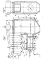
- La figure 1 représente une coupe schématique longitudinale d'un exemple du dispositif selon l'invention.
- La figure 2 représente une vue schématique de la zone de solidification (12).
- Figure 1 shows a schematic longitudinal section of an example of the device according to the invention.
- FIG. 2 represents a schematic view of the solidification zone (12).
La zone de combustion (5) est alimentée en suspension solide-liquide par l'intermédiaire de la ligne (1). Les lignes (2) et (3) conduisent respectivement l'air de pulvérisation et l'air de combustion au brûleur multifluide (4).The combustion zone (5) is supplied with solid-liquid suspension via the line (1). Lines (2) and (3) lead the spray air and the combustion air respectively to the multi-fluid burner (4).
Ce brûleur (4) est disposé sur le mur avant (6) fixe de la zone (5). Les parois de cette zone sont constituées de réfractaires (7) d'une épaisseur d'environ 350 mm, maintenus en place par l'enveloppe extérieure métallique (8). La zone (5) inclinée d'un angle a de 3,5° sur l'horizontale est mise en rotation au moyen d'un système comportant un galet moteur (9) et un galet support (10) sur lesquels s'appuient les chemins de roulement (11). ).This burner (4) is arranged on the fixed front wall (6) of the zone (5). The walls of this area are made of refractories (7) with a thickness of about 350 mm, held in place by the metallic outer casing (8). The area (5) inclined at an angle a of 3.5 ° to the horizontal is rotated by means of a system comprising a drive roller (9) and a support roller (10) on which the raceways (11). ).
La zone (5) débouche sur une zone de solidification (12), revêtant la forme d'un parallélépipède rectangle. L'intérieur des parois de la zone (12) est tapissé de tubes (13) destinés à l'échange thermique par rayonnement, lesdites parois étant constituées d'un revêtement réfractaire isolant intérieur (14) de 100 mm d'épaisseur environ maintenu en place par une enveloppe métallique (15). Dans la partie basse de la zone (12) est disposée une trémie (16) destinée à récupérer les scories et les cendres. Les parois de la trémie sont constituées de manière analogue à celle de la partie échange thermique de la zone (12).The zone (5) opens onto a solidification zone (12), taking the form of a rectangular parallelepiped. The inside of the walls of the zone (12) is lined with tubes (13) intended for heat exchange by radiation, said walls being made of an insulating refractory lining inside (14) of approximately 100 mm thickness maintained in placed by a metal casing (15). In the lower part of the zone (12) is arranged a hopper (16) intended to collect the slag and the ash. The walls of the hopper are made in a similar way to that of the heat exchange part of the zone (12).
La zone (12) débouche sur une zone de convection (17) disposée perpendiculairement à la zone (12). Cette zone (17) est équipée d'une batterie de tubes (18) destinés à l'échange thermique par convection. Des conduites (19) collectent l'émulsion vapeur-eau produite à la fois par les tubes (13) et les tubes (18) pour la diriger vers le ballon séparateur (20). La zone (17) est équipée à sa partie basse de trémies (21) pour la récupération des poussières véhiculées par le flux gazeux et des dépôts éventuels sur les tubes (18), détachés au moyen d'un système de soufflage classique non représenté. Les parois de la zone (17) sont constituées d'un réfractaire isolant (22) d'une épaisseur de 50 mm environ maintenu en place par l'enveloppe (23).The zone (12) opens onto a convection zone (17) arranged perpendicular to the zone (12). This zone (17) is equipped with a battery of tubes (18) intended for heat exchange by convection. Lines (19) collect the steam-water emulsion produced by both the tubes (13) and the tubes (18) to direct it to the separator flask (20). The zone (17) is equipped at its lower part with hoppers (21) for the recovery of dust conveyed by the gas flow and possible deposits on the tubes (18), detached by means of a conventional blowing system not shown. The walls of the zone (17) consist of an insulating refractory (22) with a thickness of approximately 50 mm held in place by the envelope (23).
A la sortie de la zone (17) le flux gazeux refroidi est aspiré par l'exhauster (25) à travers un dépoussiéreur (24) avant rejet à la cheminée (26).At the exit of the zone (17) the cooled gas flow is sucked by the exhaust (25) through a dust collector (24) before discharge to the chimney (26).
Le dispositif de l'invention décrit ci-dessus est mis en oeuvre selon le processus décrit ci-après avec comme combustible une suspension charbon-eau. Cette suspension est constituée d'un mélange pondéral 40 % eau, 60 % charbon. Ce charbon a été finement broyé en milieu aqueux de façon à obtenir une granulométrie centrée sur 35 microns avec un maximum de 100 microns. La viscosité du mélange est réduite par addition d'un produit tensio actif approprié.The device of the invention described above is implemented according to the process described below with a coal-water suspension as fuel. This suspension consists of a weight mixture of 40% water, 60% carbon. This carbon was finely ground in an aqueous medium so as to obtain a particle size centered on 35 microns with a maximum of 100 microns. The viscosity of the mixture is reduced by adding an appropriate surfactant.
Le combustible est introduit par pompage volumétrique dans le brûleur, ce dernier étant alimenté séparément en air surpressé de pulvérisation à 0,7 bar effectif et en air de combustion. Le jet pulvérisé est injecté dans l'axe de la zone de combustion dont la conception permet la combustion totale du charbon contenu dans la suspension au sein même de cette zone avec un taux de combustion atteignant 600 thermies par m3 de zone de combustion. L'allumage du combustible est assuré automatiquement par le niveau de température régnant dans la zone préalablement préchauffée à 1100°C avec du fuel classique. Dès lors la température en régime stabilisé est de l'ordre de 1400°C. La charge thermique est modulée en fonction des besoins par action directe sur la pompe volumétrique d'alimentation. La souplesse ainsi obtenue permet une variation instantanée du débit calorifique dans les proportions de 1/5 à 5/5. Aux températures atteintes les cendres contenues dans le charbon se trouvent à l'état liquide en fine suspension dans les gaz de combustion, Une fraction de ces particules se dépose au contact des parois réfractaires sur lesquelles elles ruissellent par gravité. Leur évacuation est assurée par la conjonction de l'inclinaison de la zone sur l'horizontale et sa mise en rotation lente.The fuel is introduced by volumetric pumping into the burner, the latter being supplied separately with compressed air sprayed at 0.7 bar effective and with combustion air. The spray is injected into the axis of the combustion zone, the design of which allows the total combustion of the coal contained in the suspension within this zone itself with a combustion rate reaching 600 therms per m3 of combustion zone. The ignition of the fuel is ensured automatically by the temperature level prevailing in the zone preheated to 1100 ° C with conventional fuel. Therefore the temperature in steady state is of the order of 1400 ° C. The thermal load is modulated as required by direct action on the supply volumetric pump. The flexibility thus obtained allows an instantaneous variation of the calorific flow in the proportions of 1/5 to 5/5. At the temperatures reached, the ash contained in the coal is in the liquid state in fine suspension in the combustion gases. A fraction of these particles is deposited in contact with the refractory walls on which they flow by gravity. Their evacuation is ensured by the conjunction of the inclination of the zone on the horizontal and its slow rotation.
Les concrétions éventuelles qui peuvent se former sur les parois sont également éliminées au fur et à mesure de leur décrochement. Ce dernier résulte en particulier de la nature antiadhérente de la paroi vis-à-vis des scories.The possible concretions which can form on the walls are also eliminated as they are detached. The latter results in particular from the non-stick nature of the wall vis-à-vis the slag.
Les gaz chaud (1400°C environ) produits dans la zone de combustion pénètrent dans la zone de solidification. Les gaz, dans cette zone, se refroidissent par rayonnement vers les parois froides tapissées de tubes ce qui provoque automatiquement le refroidissement concomitant des fines particules cendreuses en fusion transportées au sein du courant gazeux. Dans cette zone la température du gaz passe de 1400 à 850°C environ. La trémie située à la partie inférieure de cette zone reçoit d'une part les cendres fondues et les concrétions issues de la zone de combustion et d'autre part celles qui pourraient se former sur la partie de la paroi en regard de combustion, puis se détacher. Les gaz issus de la zone solidification pénètrent dans la zone de convection où ils sont refroidis, jusqu'à une température de 250°C environ au contact des faisceaux de tubes échangeurs. Dans cette zone une fraction des pous" sières se dépose sur les tubes d'où elles sont chassées par un procédé classique de soufflage.The hot gases (around 1400 ° C) produced in the combustion zone penetrate into the solidification zone. The gases in this zone cool down by radiation towards the cold walls lined with tubes, which automatically causes the concomitant cooling of the fine ashy molten particles transported within the gas stream. In this zone the temperature of the gas goes from 1400 to 850 ° C approximately. The hopper located at the lower part of this zone receives on the one hand the molten ash and the concretions coming from the combustion zone and on the other hand those which could form on the part of the wall facing combustion, then detach. The gases from the solidification zone penetrate into the convection zone where they are cooled, to a temperature of approximately 250 ° C. in contact with the bundles of exchanger tubes. In this area a fraction of lice "Sieres deposits on the tubes where they are driven by a conventional method for blow molding.
Des trémies disposées à la base recoivent les poussières chutant par gravité, L'émulsion eau- vapeur générée dans les faisceaux d'échange des zones de solidification et de convection est collectée à la partie supérieure et dirigée vers le ballon séparateur.Hoppers arranged at the base receive the dust falling by gravity. The water-steam emulsion generated in the exchange beams of the solidification and convection zones is collected at the top and directed towards the separating flask.
Les gaz issus de la zone de convection sont dépoussiérées de manière classique avant le rejet à la cheminée.The gases from the convection zone are dusted in a conventional manner before being discharged to the chimney.
Les dispositifs de l'invention sont particulièrement avantageux car ils permettent l'utilisation comme combustible liquide des charbons de toutes natures dans des conditions d'exploitation particulièrement favorables notamment aux niveaux de la manutention, de l'extraction des cendres, de la souplesse de fonctionnement et de la sécurité.The devices of the invention are particularly advantageous because they allow the use of coals of all kinds as liquid fuel under particularly favorable operating conditions, particularly in terms of handling, ash extraction, flexibility of operation. and security.
De plus, il est à noter qu'en utilisant les moyens de l'invention il est aisé de convertir au charbon des chaudières existantes, et conçues pour les combustibles hydrocarbonés classiques. Pour cela, il suffira essentiellement d'ajouter une zone de combustion selon l'invention à adapter aux caractéristiques de la chaudière existante.In addition, it should be noted that by using the means of the invention it is easy to convert coal to existing boilers, and designed for conventional hydrocarbon fuels. For this, it will suffice essentially to add a combustion zone according to the invention to adapt to the characteristics of the existing boiler.
Claims (3)
a third zone (17) for thermal exchange by convection via a tubuar network (18) equipped in its lower part with dust hoppers (21) and connected to the flushing systems (24) for gas and unwatering (25), characterized by the fact that the combustion organ (4) is a multi-fluid burner adapted to. burn solid fuel suspended in a liquid, and that in the first combustion zone (5) the fuel is pulverized axially by an auxiliary fluid adapted to the fuel being used, and that the combustion zones shown (5,12) and the solidification zone are associated via the following geometrical relationships expressed as a function of the parameter D:
Priority Applications (1)
| Application Number | Priority Date | Filing Date | Title |
|---|---|---|---|
| AT83401755T ATE39745T1 (en) | 1982-09-10 | 1983-09-06 | BOILER-TYPE DEVICE USING A SOLID-LIQUID SUSPENSION OF THE COAL-WATER TYPE. |
Applications Claiming Priority (2)
| Application Number | Priority Date | Filing Date | Title |
|---|---|---|---|
| FR8215359A FR2533018B1 (en) | 1982-09-10 | 1982-09-10 | BOILER-TYPE DEVICE USING A SOLID-LIQUID SUSPENSION OF THE COAL-WATER TYPE AS A FUEL |
| FR8215359 | 1982-09-10 |
Publications (2)
| Publication Number | Publication Date |
|---|---|
| EP0107527A1 EP0107527A1 (en) | 1984-05-02 |
| EP0107527B1 true EP0107527B1 (en) | 1989-01-04 |
Family
ID=9277360
Family Applications (1)
| Application Number | Title | Priority Date | Filing Date |
|---|---|---|---|
| EP83401755A Expired EP0107527B1 (en) | 1982-09-10 | 1983-09-06 | Device of the boiler-type using a solid-liquid suspension of the coal-water-type as fuel |
Country Status (4)
| Country | Link |
|---|---|
| EP (1) | EP0107527B1 (en) |
| AT (1) | ATE39745T1 (en) |
| DE (1) | DE3378841D1 (en) |
| FR (1) | FR2533018B1 (en) |
Family Cites Families (5)
| Publication number | Priority date | Publication date | Assignee | Title |
|---|---|---|---|---|
| US1705383A (en) * | 1924-04-17 | 1929-03-12 | Mines De Frankenholz Soc D | Combustion chamber for use with powdered fuel |
| GB714749A (en) * | 1951-06-27 | 1954-09-01 | Babcock & Wilcox Ltd | Improvements in or relating to tubulous vapour generators |
| FR1339743A (en) * | 1962-10-29 | 1963-10-11 | Combustion Eng | Improvements to processes and installations for handling and burning coal |
| FR2088628A5 (en) * | 1970-04-20 | 1972-01-07 | Heurtey Sa | |
| DE2418504C2 (en) * | 1974-04-11 | 1982-10-28 | Heinrich Dr.-Ing. 1000 Berlin Vorkauf | Pipe element for heating surface group of a heat exchanger |
-
1982
- 1982-09-10 FR FR8215359A patent/FR2533018B1/en not_active Expired
-
1983
- 1983-09-06 DE DE8383401755T patent/DE3378841D1/en not_active Expired
- 1983-09-06 AT AT83401755T patent/ATE39745T1/en not_active IP Right Cessation
- 1983-09-06 EP EP83401755A patent/EP0107527B1/en not_active Expired
Also Published As
| Publication number | Publication date |
|---|---|
| FR2533018A1 (en) | 1984-03-16 |
| ATE39745T1 (en) | 1989-01-15 |
| EP0107527A1 (en) | 1984-05-02 |
| DE3378841D1 (en) | 1989-02-09 |
| FR2533018B1 (en) | 1985-07-19 |
Similar Documents
| Publication | Publication Date | Title |
|---|---|---|
| FR2484280A1 (en) | FLUIDIZED BED REACTOR AND METHOD FOR COMBUSTING MATERIALS CONTAINING INCOMBUSTIBLE SUBSTANCES USING THE SAME | |
| BE798816A (en) | FLUIDIFIED BED INSTALLATION FOR DESTRUCTION OF DETRITUS | |
| FR2486223A1 (en) | HEAT EXCHANGER WITH FLUIDIZED BED | |
| FR2854887A1 (en) | Thermal recycling system suitable for waste material with high water content has thermopyrolysis. solid and gas combustion systems and heat exchanger with condenser | |
| EP0119115A1 (en) | Heat generator for heating a fluid by heat exchange with a fluidized bed, and method for putting it into operation | |
| FR2553497A1 (en) | PROCESS FOR BURNING FLUIDIZED BED FUEL | |
| FR2463893A1 (en) | METHOD AND APPARATUS FOR SELF-MAINTAINING INCINERATION OF EASILY FRIABLE COMBUSTIBLE AGGLOMERES WITH HIGH WATER CONTENT | |
| EP0107527B1 (en) | Device of the boiler-type using a solid-liquid suspension of the coal-water-type as fuel | |
| EP0665407A1 (en) | System for the injection of sludge for incineration in an incinerating oven, corresponding method of operation, use and oven | |
| EP0123339B1 (en) | Heating apparatus | |
| EP0485255A1 (en) | Process and apparatus for the production of a solid fuel from combustible wastes | |
| FR2485178A1 (en) | IMPROVEMENTS IN DEVICES FOR REACTING, SUCH AS COMBUSTION, BETWEEN A SOLID AND A GAS | |
| WO1996040837A1 (en) | Fluidized bed reactor for the heat treatment of waste material | |
| EP1247046B1 (en) | Method and device for the autocombustion of oily organic waste, comprising a tangential heating furnace | |
| US5257587A (en) | Method and apparatus for introducing and incinerating solid combustible waste in a rotary kiln | |
| EP2479493B1 (en) | Combustion device, incineration unit comprising such a combustion device, and method for implementing such a combustion device | |
| EP0142388B1 (en) | High pressure fluidised bed coal gasifier | |
| EP0553019B1 (en) | Method for burning solid fuels with a high content of fusible ashes and heavy metals | |
| EP3960837A1 (en) | Fixed-bed pyro-gasification reactor with improved efficiency | |
| EP0568202A1 (en) | Method of incinerating waste in a rotary kiln plant, and plant therefor | |
| EP0970326A1 (en) | Incinerator and method for incinerating liquid, pasty and solid waste | |
| FR2572952A1 (en) | Fume purification process and plant. | |
| EP3816512A1 (en) | Module for producing heat including a high-temperature filtering system | |
| EP0292406A1 (en) | Process for producing a hot fluid and boiler for carrying out this process | |
| BE892972A (en) | Pneumatic extractor for fluidised bed - has pulsating airstream circulating through diffusing tank |
Legal Events
| Date | Code | Title | Description |
|---|---|---|---|
| PUAI | Public reference made under article 153(3) epc to a published international application that has entered the european phase |
Free format text: ORIGINAL CODE: 0009012 |
|
| 17P | Request for examination filed |
Effective date: 19830909 |
|
| AK | Designated contracting states |
Designated state(s): AT BE DE GB IT NL |
|
| RAP1 | Party data changed (applicant data changed or rights of an application transferred) |
Owner name: PARIEL, JEAN-MARIE |
|
| RIN1 | Information on inventor provided before grant (corrected) |
Inventor name: PARIEL, JEAN-MARIE |
|
| GRAA | (expected) grant |
Free format text: ORIGINAL CODE: 0009210 |
|
| AK | Designated contracting states |
Kind code of ref document: B1 Designated state(s): AT BE DE GB IT NL |
|
| PG25 | Lapsed in a contracting state [announced via postgrant information from national office to epo] |
Ref country code: NL Effective date: 19890104 Ref country code: AT Effective date: 19890104 |
|
| REF | Corresponds to: |
Ref document number: 39745 Country of ref document: AT Date of ref document: 19890115 Kind code of ref document: T |
|
| REF | Corresponds to: |
Ref document number: 3378841 Country of ref document: DE Date of ref document: 19890209 |
|
| ITF | It: translation for a ep patent filed |
Owner name: DOTT. ING. FRANCO RASTELLI |
|
| GBT | Gb: translation of ep patent filed (gb section 77(6)(a)/1977) | ||
| NLV1 | Nl: lapsed or annulled due to failure to fulfill the requirements of art. 29p and 29m of the patents act | ||
| PLBE | No opposition filed within time limit |
Free format text: ORIGINAL CODE: 0009261 |
|
| STAA | Information on the status of an ep patent application or granted ep patent |
Free format text: STATUS: NO OPPOSITION FILED WITHIN TIME LIMIT |
|
| 26N | No opposition filed | ||
| ITTA | It: last paid annual fee | ||
| PGFP | Annual fee paid to national office [announced via postgrant information from national office to epo] |
Ref country code: GB Payment date: 19920306 Year of fee payment: 9 Ref country code: BE Payment date: 19920306 Year of fee payment: 9 |
|
| PGFP | Annual fee paid to national office [announced via postgrant information from national office to epo] |
Ref country code: DE Payment date: 19920320 Year of fee payment: 9 |
|
| PG25 | Lapsed in a contracting state [announced via postgrant information from national office to epo] |
Ref country code: GB Effective date: 19920906 |
|
| PG25 | Lapsed in a contracting state [announced via postgrant information from national office to epo] |
Ref country code: BE Effective date: 19920930 |
|
| BERE | Be: lapsed |
Owner name: PARIEL JEAN-MARIE Effective date: 19920930 |
|
| GBPC | Gb: european patent ceased through non-payment of renewal fee |
Effective date: 19920906 |
|
| PG25 | Lapsed in a contracting state [announced via postgrant information from national office to epo] |
Ref country code: DE Effective date: 19930602 |