EP0107475A2 - Bohrmeisselanordnung mit Flüssigkeitsabscheider - Google Patents
Bohrmeisselanordnung mit Flüssigkeitsabscheider Download PDFInfo
- Publication number
- EP0107475A2 EP0107475A2 EP83306327A EP83306327A EP0107475A2 EP 0107475 A2 EP0107475 A2 EP 0107475A2 EP 83306327 A EP83306327 A EP 83306327A EP 83306327 A EP83306327 A EP 83306327A EP 0107475 A2 EP0107475 A2 EP 0107475A2
- Authority
- EP
- European Patent Office
- Prior art keywords
- flow
- plenum chamber
- fluid
- conduit means
- bit assembly
- Prior art date
- Legal status (The legal status is an assumption and is not a legal conclusion. Google has not performed a legal analysis and makes no representation as to the accuracy of the status listed.)
- Granted
Links
Images
Classifications
-
- E—FIXED CONSTRUCTIONS
- E21—EARTH OR ROCK DRILLING; MINING
- E21B—EARTH OR ROCK DRILLING; OBTAINING OIL, GAS, WATER, SOLUBLE OR MELTABLE MATERIALS OR A SLURRY OF MINERALS FROM WELLS
- E21B10/00—Drill bits
- E21B10/08—Roller bits
- E21B10/22—Roller bits characterised by bearing, lubrication or sealing details
- E21B10/23—Roller bits characterised by bearing, lubrication or sealing details with drilling fluid supply to the bearings
-
- E—FIXED CONSTRUCTIONS
- E21—EARTH OR ROCK DRILLING; MINING
- E21B—EARTH OR ROCK DRILLING; OBTAINING OIL, GAS, WATER, SOLUBLE OR MELTABLE MATERIALS OR A SLURRY OF MINERALS FROM WELLS
- E21B10/00—Drill bits
- E21B10/08—Roller bits
- E21B10/18—Roller bits characterised by conduits or nozzles for drilling fluids
-
- E—FIXED CONSTRUCTIONS
- E21—EARTH OR ROCK DRILLING; MINING
- E21B—EARTH OR ROCK DRILLING; OBTAINING OIL, GAS, WATER, SOLUBLE OR MELTABLE MATERIALS OR A SLURRY OF MINERALS FROM WELLS
- E21B21/00—Methods or apparatus for flushing boreholes, e.g. by use of exhaust air from motor
- E21B21/002—Down-hole drilling fluid separation systems
-
- E—FIXED CONSTRUCTIONS
- E21—EARTH OR ROCK DRILLING; MINING
- E21B—EARTH OR ROCK DRILLING; OBTAINING OIL, GAS, WATER, SOLUBLE OR MELTABLE MATERIALS OR A SLURRY OF MINERALS FROM WELLS
- E21B21/00—Methods or apparatus for flushing boreholes, e.g. by use of exhaust air from motor
- E21B21/16—Methods or apparatus for flushing boreholes, e.g. by use of exhaust air from motor using gaseous fluids
Definitions
- the present invention relates generally to drill bit assemblies and, more particularly, to such a drill bit assembly having a plurality of rotary cutting cones for use with a rotary drill for drilling into a relatively hard material, such as rock and the like.
- Typical prior art rotary drill bit assemblies used for drilling into rock or other such relatively hard material comprise an elongated generally tubular housing or adapter sub to which is attached a bit which includes a plurality (generally three) of bearing mounted rotary cutting cones on the lower end thereof.
- the upper end of the adapter sub is adapted to engage for rotation a rotary drill, either directly or through the use of a suitable extension drill pipe when drilling deep holes.
- the adapter sub includes a central conduit which extends from the rotary drill (or the extension pipe) to the vicinity of the cutting cones. During the drilling operation, pressurized air from the rotary drill flows (either directly or via the.
- extension pipe through the central conduit in the adapter sub and is discharged downwardly either directly or through jet nozzles positioned between the rotating cutting cones.
- the discharged air impinges upon the rock or other such material being drilled and acts as a scavenging medium to pick up dust, cuttings and other such debris and carries them upwardly past the rotating cutting cones and out of the drill hole.
- Water or other such wetting agents may be added to the air flow continuously or intermittently as required to help control the dust generated by the drilling operation.
- a portion of the air flow may also be circulated by a second conduit through the cutting cone bearings to cool the bearings and to help prevent the entry of dust from the cuttings or other extraneous material into the bearings.
- the present invention provides an improved drill bit assembly for drilling a generally circular hole into a relatively hard material, such as rock.
- the bit assembly comprises an elongated housing having a drill end adapted for attachment to a rotary drill and a tool end for receiving a tool having at least one cutting cone, for engaging and cutting a drill hole into the material to be drilled.
- a plenum chamber is located within the housing for receiving pressurized gaseous fluid from a fluid source.
- First conduit means is provided within the housing for directing a first flow of fluid from the plenum chamber out of the housing adjacent the at least one cutting cone into the drill hole and into impingement upon the material being drilled to pick up and remove along the housing dust and cuttings from the vicinity of the cutting cone.
- Separator means is supported within the plenum chamber on housing walls defined by that chamber proximate the first conduit means for separating moisture out of the first flow of fluid prior to the first flow entering the first conduit means.
- Second conduit means is provided within the housing for discharging generally, toward the drill end of the housing, a second flow of fluid out of the plenum chamber away from the cutting cone.
- the first flow of fluid is designed to be of sufficient magnitude for conveying dust and cuttings removed from the vicinity of the cutting cone into the second fluid flow, which is of sufficient magnitude to convey the dust and cuttings away from the bit assembly and out of the drill hole.
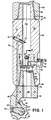
- FIG. 1 there is shown a sectional view of a preferred embodiment of a drill bit assembly, generally designated 10, in accordance with the present invention.
- a drill bit assembly of the type shown may be used in conjunction with a standard rotary drill (not shown) for drilling into relatively hard material, such as rock or the like (not shown) and has found particular application in connection with coal mining.
- the drill bit assembly 10 is generally comprised of two major subassemblies; an adapter subassembly or “adapter sub” 12 and a bit subassembly or “bit” 14, which provides the cutting tool.
- the bit 14 comprises an irregularly shaped housing 18 having a frustoconically-shaped nipple 20 for engaging a complementary sized and shaped tapered socket 21 on the adapter sub 12 as shown.
- the nipple 20 and socket 21 are threaded as indicated at 16 to releasably secure the adapter sub 12 and the bit 14 to form a complete drill bit assembly 10.
- the "bit” assembly housing 18 is adapted to rotatably support three rotary cutters or cutting cones 22 (only one of which is shown on Fig. 1 for purposes of clarity).
- the cutting cones 22 are each journalled for independent rotation upon bearings 24 which, in the present embodiment, comprise suitable anti-friction bearings.
- Suitable sealing means may be provided to prevent debris from entering the area between the cutting cones 22 and the underlying supporting housing 18 and from contacting the bearings 24.
- the exterior surface of each of the cutting cones 22 may include a plurality of cutting teeth 26 which are employed for cutting into rock and other hard materials upon rotation of the drill bit 10 during the drilling operation.
- the teeth 26, as well as the other components of the cutting cones 22, are generally comprised of (or at least faced with) a relatively hard material such as tungsten carbide or the like.
- the bit housing 18 includes a generally cylindrically-shaped open conduit 28 extending centrally through from the end of the nipple 20 to the vicinity of the cutting cones 22.
- Bit assemblies of the general type shown and described are well known in the art and may be purchased commercially in various configurations from several bit manufacturing companies, such as, Varel Manufacturing Company of Dallas, Texas. A more complete description of the detailed structure and operation of the conventional bit may be obtained from the manufacturer, if desired.
- the adapter sub 12 is comprised of a generally cylindrically-shaped elongated housing 30 having a coaxial frustoconically shaped drill end 32.
- the drill end 32 of the housing may include suitable threading 34 and is adapted for engagement with drill pipe extension 33, usually through the intermediate rotary drill (not shown).
- the adapter sub housing 30 includes a cylindrical bore 40 which extends coaxially through the housing 30 from the drill end 32 to the tool end 36 and provides the fluid retaining plenum chamber.
- pressurized fluid usually compressed from a supply source of air under pressure (not shown) which is maintained within or located adjacent to the surface-mounted rotary drill drive (not shown), is supplied through series of pipes forming the connection to the drill bit assembly.
- extension pipes 33 are added, the pressurized air is supplied through a suitable coupling to the pipes and to the bore of plenum chamber 40 of adapter sub housing 30.
- the pressurized air enters the plenum chamber 40 at the first housing end 32.
- the received air is thereafer distributed in a manner similar to, but somewhat modified from that described and claimed in our aforesaid copending European patent application.
- the amount of air exiting the plenum chamber 40 is determined by the size of opening of annular orifice 48.
- the orifice plate 46 is held in place against shoulder 47 by snap ring 45. Since only one orifice plate is used much reduced supply pressure may be used in this device, than in the aforesaid copending application structure.
- Flow through opening 48 results in a first air flow which enters the bit conduit 28 and whose pressure is very substantially reduced from that supplied to the plenum chamber 40.
- the first flow is directed downwardly through a first conduit and is discharged between the cutting cones 22 for impingement upon the material being drilled.
- the structure at orifice 48 employs a modified structure, which will be explained below.
- the purpose of the first air flow exiting from the plenum chamber 40 is to cool the surface of the cutting cones 22 and to serve as a circulating medium to pick up and exhaust or remove dust and material cuttings from the drill hole in the vicinity of the cutting cones 22.
- the force of the first air flow serves to convey the cuttings and dust upwardly past the cutting cones 22 and around the outer surface of the drill bit 10 between the bit and the bore wall.
- This first flow leaves the housing adjacent the cutting cones to impinge upon the material being drilled for the removal of the dust and cuttings in the vicinity of the cutting cones 22.
- the pressure of the first air flow out of the plenum chamber 50 need only be of sufficient magnitude to pick up and remove the dust and cuttings from around the cutting cones 22 and to convey the dust and cuttings a short distance upwardly to be picked up and removed from the drill hole by a second flow, in a manner as will hereinafter be described.
- Three passages 52 extend from the plenum chamber 40 through the housing 30 to provide second conduit means for discharging a second flow of fluid from the plenum chamber.
- the passages 52 are disposed generally equidistantly from each other around the circumference of housing at a common axial level proximate to the annular orifice plate 46.
- Each passage 52 extending radially outwardly and slightly downwardly toward the bit.
- Three similar right angle elbow jet nozzle assemblies 56 (only one of which is shown in Fig. 1) are each mounted on a flat surface normal to bore 54 in a niche 53 on the outer surface of the adapter sub housing 30.
- Each jet nozzle assembly has a jet producing orifice ring 58 seated on a shoulder 59 at its outlet and held in place with suitable fastening means such as a snap ring 60.
- the nozzles point generally toward the drill end 32 of the housing and direct the flow against the walls of the bore at a small angle for easy deflection.
- air from the plenum chamber 40 flows through the second conduit means 52, through the passage 54 and the jet nozzle assemblies 56 and out of the jet nozzle orifices 58 toward the first drill end of the housing.
- the flow is confined between the walls of the drilled bore hole (not shown) and initially the walls of the housing 30, and thereafter the drill pipe extensions 33.
- the flow of air exiting from the jet nozzle orifices 58 operates as a scavenging flow and picks up or combines with the above-described first air flow out of the plenum chamber 50 for further conveying the dust and cuttings removed from the vicinity of the cutting cones upwardly and out of the drill hole.
- the relative amount of first and second flows of fluid may be adjusted.
- the first flow is kept at a low level sufficient only to efficiently convey away the abrasive dust and cuttings from the drill bit 10 and out and up into the second flow resulting in a significant decrease in the sandblasting effect encountered by the cutting cones 22.
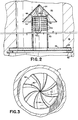
- the orifice in oriface plate 46 is covered by separator means having a stand pipe 62 which is cup shaped, to enclose the orifice and the stand pipe projects into the plenum chamber 40.
- the stand pipe 62 is closed at its upper end but has a plurality of radial perforations 62a in several axial planes extending downwardly from the closed top. These perforations 62a permit the passage of pressurized air from the plenum chamber 40 through the orifice plate 46 and conduit 28 to the region of the cutting cones 22.
- Perforations 62a are oriented perpendicular to the flow of air through the plenum chamber and are of sufficient size and number not to reduce the flow of air through into the stand pipe and through the orifice plate 46 which would correspond to that which would be permitted by the relative orifice size of plate 46. However, it will be observed that the perforations in stand pipe 62a are remote from the orifice ring 46. Preferably located axially between the orifice plate 46 and the perforations 62a, the passages 52 permit formation of the larger volume of a secondary flow of air to provide the major conveying streams. Covering the closed end of the stand pipe 62 is a conical fluid deflector 64 arranged coaxially with the stand pipe.
- deflector 64 extend radially beyond the walls of the stand pipe 65, and axially below the closed end of the stand pipe.
- the deflector 64 serves at least the function of an air flow deflector and may also provide flow acceleration.
- the cover also may be flatter or steeper, employ various other shapes, such as oval, and employ various types of curved conical shapes instead of straight line elements.
- the conical face of the deflector is preferably provided with vanes or fins 66, which in this embodiment are shown in spiral or semi-helical arrangements and which tend to cause a spiralling or swirling of the pressurized air fluid as it moves past deflector 64 in the plenum chamber 40 and toward the passages 52.
- the conical deflector 64 is supported relative to the closed end of stand pipe 62 by struts 68 which extend between and are fixed to the stand pipe and the deflector.
- the deflector 64 not only deflects the air coming toward the passages 52 but also, at the same time, due to the constriction between the deflector 64 and the walls of the plenum chamber 40, produces an orifice effect.
- the orifice effect creates a centrifugal action on the air tending to cause the heavier water particles, which are in the air to provide a wetting agent to control dust generated by the drilling operation, to precipitate out.
- the deflector 64 also necessitates a circuitous return of some of that air back to the perforations 62a.
- the deflector is placed so as not to obstruct those perforations 62a or otherwise impede the first flow of air through the orifice in plate 46.
- Air molecules are freer than heavier water particles to make the turn back upwardly under the deflector 64 to form the first flow of air relatively free of water.
- This first flow of air passes through the perforations 62a and down through the stand pipe 62 and the orifice in plate 46 and through conduit 28. Consequently, air which is relatively free of water reaches the cutting areas and the tendency to form mud and otherwise clog the drilling area due to high moisture content is substantially reduced.
- Air which may contain a considerable amount of water is more easily carried in the second flow of fluid out through the passages 52.
- water may tend to be precipitated out but during normal operation the rate of the second flow through passages 52 is such that no water accumulates in the plenum chamber adjacent the stand pipe 62.
- the stand pipe 62 is designed so that its perforations are always above water level, although the possibility exists that water may rise high enough to_enter the passages 52 which are placed below the perforations.
- that water is generally re-evaporated and carried outward by the second flow of air through passages 52 when drilling and the air supply is resumed.
- Air lubrication is accomplished by air taken in through air intake 70 or a plurality of similar intakes, into an associated passage 72.
- Each passage 72 is formed by a bore through the wall 12 of housing 30 from the plenum chamber to the outside, tilted from the radial away from the direction of flow into plenum chamber 40.
- a tubular member 70 placed within the bore 72 projects into the plenum chamber.
- Tubular member 70 may be cut on the bias to provide a deflector projecting into the plenum chamber 40.
- the deflector overhang allows the air moving into and through the plenum chamber to be deflected by the deflector portion of the tube 70 and requires the air to double back to turn into the tube 70. This allows air much more readily than water to turn into this devious course at tube 70, whereas, water-ladened air, or water particles, tends to go directly toward the bottom of the plenum chamber past tube 70.
- Passage 72 is closed to the outer wall by a plug 74.
- the flow of air proceeds down a passage 76 parallel to the axis, or a plurality of similar passages, into a segmented ring passage 78, similar to that used for oil lubrication at the interface between housing 30 and bit subassembly 14 as described in the aforesaid copending application.
- the ring passage 78 feeds feeder passages 80, in the bit subassembly running generally parallel to the axis.
- Passages 80 feed main lubrication passage 82 and various spur passages 84 off of passage 82 to bearing regions needing lubrication and cooling.
- Passage 82 is formed by boring and is closed at the outside wall by a plug, such as a screw as shown. The air lubrication which is accomplished in this manner is accomplished with air which is relatively free in moisture.
- the moisture in the air passing through the plenum chamber 40 is either carried directly out by the three streams constituting the second flow through passages 52 or is precipitated into a pool adjacent the stand pipe 62 as previously described. Water in the pool is quickly re- evaporated to be carried out by the three streams entering passages 52 (see Fig. 1) and thus is caused to bypass the cutting region of the tool. Therefore, moisture is not given a chance to cause problems by creating mud in the bottom of the bore hole and moisture problems are avoided in the working area of the drill bits, the cutting cones of the tools and the bearings thereof.
Landscapes
- Engineering & Computer Science (AREA)
- Life Sciences & Earth Sciences (AREA)
- Geology (AREA)
- Mining & Mineral Resources (AREA)
- Mechanical Engineering (AREA)
- Physics & Mathematics (AREA)
- Environmental & Geological Engineering (AREA)
- Fluid Mechanics (AREA)
- General Life Sciences & Earth Sciences (AREA)
- Geochemistry & Mineralogy (AREA)
- Earth Drilling (AREA)
Priority Applications (1)
| Application Number | Priority Date | Filing Date | Title |
|---|---|---|---|
| AT83306327T ATE39539T1 (de) | 1982-10-19 | 1983-10-18 | Bohrmeisselanordnung mit fluessigkeitsabscheider. |
Applications Claiming Priority (4)
| Application Number | Priority Date | Filing Date | Title |
|---|---|---|---|
| US06/435,239 US4541494A (en) | 1982-10-19 | 1982-10-19 | Drill bit assembly |
| US435239 | 1982-10-19 | ||
| US06/503,322 US4515229A (en) | 1983-06-10 | 1983-06-10 | Drill bit assembly with fluid separator |
| US503322 | 1983-06-10 |
Publications (3)
| Publication Number | Publication Date |
|---|---|
| EP0107475A2 true EP0107475A2 (de) | 1984-05-02 |
| EP0107475A3 EP0107475A3 (en) | 1986-02-05 |
| EP0107475B1 EP0107475B1 (de) | 1988-12-28 |
Family
ID=27030481
Family Applications (1)
| Application Number | Title | Priority Date | Filing Date |
|---|---|---|---|
| EP19830306327 Expired EP0107475B1 (de) | 1982-10-19 | 1983-10-18 | Bohrmeisselanordnung mit Flüssigkeitsabscheider |
Country Status (2)
| Country | Link |
|---|---|
| EP (1) | EP0107475B1 (de) |
| DE (1) | DE3378779D1 (de) |
Cited By (3)
| Publication number | Priority date | Publication date | Assignee | Title |
|---|---|---|---|---|
| AU2005248954B2 (en) * | 2005-12-23 | 2011-03-17 | John Brodie | Rock drill water separator |
| AU2008258269B2 (en) * | 2007-06-04 | 2015-04-23 | Cardinal Trading Company Pty Ltd | Apparatus for use in drilling |
| US9822589B2 (en) | 2014-12-05 | 2017-11-21 | Atlas Copco Secoroc Llc | Rotary drill bit air/water separator |
Families Citing this family (1)
| Publication number | Priority date | Publication date | Assignee | Title |
|---|---|---|---|---|
| US20250129673A1 (en) * | 2023-10-23 | 2025-04-24 | Schlumberger Technology Corporation | Devices, systems, and methods for a cutting element |
Family Cites Families (9)
| Publication number | Priority date | Publication date | Assignee | Title |
|---|---|---|---|---|
| US3123159A (en) * | 1964-03-03 | Jet underreaming | ||
| US2634101A (en) * | 1949-07-08 | 1953-04-07 | Sloan Pearl | Apparatus for accelerating the removal of cuttings from the bottom of wells |
| US2861780A (en) * | 1956-06-20 | 1958-11-25 | Jimmy L Butler | Means for cooling the cutters of drill bits |
| US2920872A (en) * | 1957-12-23 | 1960-01-12 | Hughes Tool Co | Water separator for air drilling |
| US3788408A (en) * | 1970-04-20 | 1974-01-29 | Dresser Ind | Rock bit water deflector and separator |
| US3924695A (en) * | 1974-10-02 | 1975-12-09 | John R Kennedy | Rotary drilling method and apparatus |
| US4083417A (en) * | 1976-11-12 | 1978-04-11 | Arnold James F | Jetting apparatus |
| DE2706290A1 (de) * | 1977-02-15 | 1978-08-17 | Skf Kugellagerfabriken Gmbh | Einrichtung zum schmieren der lager von schneidrollen eines rollenmeissels |
| US4287957A (en) * | 1980-05-27 | 1981-09-08 | Evans Robert F | Cooling a drilling tool component with a separate flow stream of reduced-temperature gaseous drilling fluid |
-
1983
- 1983-10-18 EP EP19830306327 patent/EP0107475B1/de not_active Expired
- 1983-10-18 DE DE8383306327T patent/DE3378779D1/de not_active Expired
Cited By (3)
| Publication number | Priority date | Publication date | Assignee | Title |
|---|---|---|---|---|
| AU2005248954B2 (en) * | 2005-12-23 | 2011-03-17 | John Brodie | Rock drill water separator |
| AU2008258269B2 (en) * | 2007-06-04 | 2015-04-23 | Cardinal Trading Company Pty Ltd | Apparatus for use in drilling |
| US9822589B2 (en) | 2014-12-05 | 2017-11-21 | Atlas Copco Secoroc Llc | Rotary drill bit air/water separator |
Also Published As
| Publication number | Publication date |
|---|---|
| EP0107475B1 (de) | 1988-12-28 |
| EP0107475A3 (en) | 1986-02-05 |
| DE3378779D1 (en) | 1989-02-02 |
Similar Documents
| Publication | Publication Date | Title |
|---|---|---|
| US4540055A (en) | Drill bit assembly having improved operational life | |
| US4515229A (en) | Drill bit assembly with fluid separator | |
| US5775443A (en) | Jet pump drilling apparatus and method | |
| US4533005A (en) | Adjustable nozzle | |
| CA1164856A (en) | Rotary drill bit | |
| US3112803A (en) | Diamond drill bit | |
| US4489793A (en) | Control method and apparatus for fluid delivery in a rotary drill string | |
| US4515227A (en) | Nozzle placement in a diamond rotating bit including a pilot bit | |
| SE460495B (sv) | Luftspaarskrapa vid jordborrkrona | |
| WO1996018020A1 (en) | Rotary cone drill bit with angled ramps | |
| US5601153A (en) | Rock bit nozzle diffuser | |
| US3055442A (en) | Drill | |
| GB2386388A (en) | Core bit having features for controlling flow split | |
| JPS6157788A (ja) | カツタ−アセンブリ | |
| CA1101837A (en) | Centrifugal water-air separation in earth drilling bits | |
| US6167975B1 (en) | One cone rotary drill bit featuring enhanced grooves | |
| US4457384A (en) | Water separator and backflow valve | |
| EP0107475B1 (de) | Bohrmeisselanordnung mit Flüssigkeitsabscheider | |
| CA1095502A (en) | Enhanced cross-flow with two jet drilling | |
| US3384192A (en) | Hydraulic jet bit | |
| EP3282083B1 (de) | Haltbarer bohrmeissel zum sprenglochbohren | |
| US2201270A (en) | Apparatus for allaying dust from rock drills | |
| EP2122107B1 (de) | Abstandshalter mit strahlablenker | |
| US2829867A (en) | Dust collecting head | |
| US4359115A (en) | Novel rotary drill bits and drilling process |
Legal Events
| Date | Code | Title | Description |
|---|---|---|---|
| PUAI | Public reference made under article 153(3) epc to a published international application that has entered the european phase |
Free format text: ORIGINAL CODE: 0009012 |
|
| AK | Designated contracting states |
Designated state(s): AT BE CH DE FR GB IT LI LU NL SE |
|
| PUAL | Search report despatched |
Free format text: ORIGINAL CODE: 0009013 |
|
| AK | Designated contracting states |
Designated state(s): AT BE CH DE FR GB IT LI LU NL SE |
|
| 17P | Request for examination filed |
Effective date: 19860725 |
|
| 17Q | First examination report despatched |
Effective date: 19870702 |
|
| GRAA | (expected) grant |
Free format text: ORIGINAL CODE: 0009210 |
|
| AK | Designated contracting states |
Kind code of ref document: B1 Designated state(s): AT BE CH DE FR GB IT LI LU NL SE |
|
| PG25 | Lapsed in a contracting state [announced via postgrant information from national office to epo] |
Ref country code: SE Effective date: 19881228 Ref country code: NL Effective date: 19881228 Ref country code: LI Effective date: 19881228 Ref country code: IT Free format text: LAPSE BECAUSE OF FAILURE TO SUBMIT A TRANSLATION OF THE DESCRIPTION OR TO PAY THE FEE WITHIN THE PRESCRIBED TIME-LIMIT;WARNING: LAPSES OF ITALIAN PATENTS WITH EFFECTIVE DATE BEFORE 2007 MAY HAVE OCCURRED AT ANY TIME BEFORE 2007. THE CORRECT EFFECTIVE DATE MAY BE DIFFERENT FROM THE ONE RECORDED. Effective date: 19881228 Ref country code: FR Free format text: THE PATENT HAS BEEN ANNULLED BY A DECISION OF A NATIONAL AUTHORITY Effective date: 19881228 Ref country code: CH Effective date: 19881228 Ref country code: BE Effective date: 19881228 Ref country code: AT Effective date: 19881228 |
|
| REF | Corresponds to: |
Ref document number: 39539 Country of ref document: AT Date of ref document: 19890115 Kind code of ref document: T |
|
| REF | Corresponds to: |
Ref document number: 3378779 Country of ref document: DE Date of ref document: 19890202 |
|
| REG | Reference to a national code |
Ref country code: CH Ref legal event code: PL |
|
| EN | Fr: translation not filed | ||
| NLV1 | Nl: lapsed or annulled due to failure to fulfill the requirements of art. 29p and 29m of the patents act | ||
| PG25 | Lapsed in a contracting state [announced via postgrant information from national office to epo] |
Ref country code: GB Effective date: 19891018 |
|
| PG25 | Lapsed in a contracting state [announced via postgrant information from national office to epo] |
Ref country code: LU Free format text: LAPSE BECAUSE OF NON-PAYMENT OF DUE FEES Effective date: 19891031 |
|
| PLBE | No opposition filed within time limit |
Free format text: ORIGINAL CODE: 0009261 |
|
| STAA | Information on the status of an ep patent application or granted ep patent |
Free format text: STATUS: NO OPPOSITION FILED WITHIN TIME LIMIT |
|
| 26N | No opposition filed | ||
| GBPC | Gb: european patent ceased through non-payment of renewal fee | ||
| PG25 | Lapsed in a contracting state [announced via postgrant information from national office to epo] |
Ref country code: DE Effective date: 19900703 |