EP0107425A2 - Radiation pattern change detection - Google Patents
Radiation pattern change detection Download PDFInfo
- Publication number
- EP0107425A2 EP0107425A2 EP83306065A EP83306065A EP0107425A2 EP 0107425 A2 EP0107425 A2 EP 0107425A2 EP 83306065 A EP83306065 A EP 83306065A EP 83306065 A EP83306065 A EP 83306065A EP 0107425 A2 EP0107425 A2 EP 0107425A2
- Authority
- EP
- European Patent Office
- Prior art keywords
- radiation
- change
- pattern
- sensitive
- sensing means
- Prior art date
- Legal status (The legal status is an assumption and is not a legal conclusion. Google has not performed a legal analysis and makes no representation as to the accuracy of the status listed.)
- Withdrawn
Links
- 230000005855 radiation Effects 0.000 title claims abstract description 80
- 230000008859 change Effects 0.000 title claims abstract description 37
- 238000001514 detection method Methods 0.000 title abstract description 9
- 230000003287 optical effect Effects 0.000 claims abstract description 26
- 238000000034 method Methods 0.000 claims description 12
- 238000005286 illumination Methods 0.000 description 11
- 230000000694 effects Effects 0.000 description 3
- 230000009467 reduction Effects 0.000 description 3
- 230000035945 sensitivity Effects 0.000 description 3
- FRLJSGOEGLARCA-UHFFFAOYSA-N cadmium sulfide Chemical compound [S-2].[Cd+2] FRLJSGOEGLARCA-UHFFFAOYSA-N 0.000 description 2
- 229910052980 cadmium sulfide Inorganic materials 0.000 description 2
- 230000001419 dependent effect Effects 0.000 description 2
- 238000004519 manufacturing process Methods 0.000 description 2
- 230000004048 modification Effects 0.000 description 2
- 238000012986 modification Methods 0.000 description 2
- 241001465754 Metazoa Species 0.000 description 1
- 208000003443 Unconsciousness Diseases 0.000 description 1
- 230000004075 alteration Effects 0.000 description 1
- 230000003321 amplification Effects 0.000 description 1
- 230000008901 benefit Effects 0.000 description 1
- 239000003990 capacitor Substances 0.000 description 1
- 230000003247 decreasing effect Effects 0.000 description 1
- 238000010586 diagram Methods 0.000 description 1
- 230000005670 electromagnetic radiation Effects 0.000 description 1
- 238000001914 filtration Methods 0.000 description 1
- 230000004907 flux Effects 0.000 description 1
- 231100001261 hazardous Toxicity 0.000 description 1
- 238000010438 heat treatment Methods 0.000 description 1
- 238000003384 imaging method Methods 0.000 description 1
- 238000009434 installation Methods 0.000 description 1
- 230000001678 irradiating effect Effects 0.000 description 1
- 238000000465 moulding Methods 0.000 description 1
- 238000003199 nucleic acid amplification method Methods 0.000 description 1
- 230000005693 optoelectronics Effects 0.000 description 1
- 230000008569 process Effects 0.000 description 1
- 230000000750 progressive effect Effects 0.000 description 1
- 238000002310 reflectometry Methods 0.000 description 1
- 230000000630 rising effect Effects 0.000 description 1
- 239000000126 substance Substances 0.000 description 1
- 238000009423 ventilation Methods 0.000 description 1
Images


Classifications
-
- G—PHYSICS
- G08—SIGNALLING
- G08B—SIGNALLING OR CALLING SYSTEMS; ORDER TELEGRAPHS; ALARM SYSTEMS
- G08B13/00—Burglar, theft or intruder alarms
- G08B13/18—Actuation by interference with heat, light, or radiation of shorter wavelength; Actuation by intruding sources of heat, light, or radiation of shorter wavelength
- G08B13/189—Actuation by interference with heat, light, or radiation of shorter wavelength; Actuation by intruding sources of heat, light, or radiation of shorter wavelength using passive radiation detection systems
- G08B13/194—Actuation by interference with heat, light, or radiation of shorter wavelength; Actuation by intruding sources of heat, light, or radiation of shorter wavelength using passive radiation detection systems using image scanning and comparing systems
- G08B13/196—Actuation by interference with heat, light, or radiation of shorter wavelength; Actuation by intruding sources of heat, light, or radiation of shorter wavelength using passive radiation detection systems using image scanning and comparing systems using television cameras
- G08B13/19602—Image analysis to detect motion of the intruder, e.g. by frame subtraction
-
- G—PHYSICS
- G08—SIGNALLING
- G08B—SIGNALLING OR CALLING SYSTEMS; ORDER TELEGRAPHS; ALARM SYSTEMS
- G08B13/00—Burglar, theft or intruder alarms
- G08B13/18—Actuation by interference with heat, light, or radiation of shorter wavelength; Actuation by intruding sources of heat, light, or radiation of shorter wavelength
- G08B13/189—Actuation by interference with heat, light, or radiation of shorter wavelength; Actuation by intruding sources of heat, light, or radiation of shorter wavelength using passive radiation detection systems
- G08B13/19—Actuation by interference with heat, light, or radiation of shorter wavelength; Actuation by intruding sources of heat, light, or radiation of shorter wavelength using passive radiation detection systems using infrared-radiation detection systems
- G08B13/191—Actuation by interference with heat, light, or radiation of shorter wavelength; Actuation by intruding sources of heat, light, or radiation of shorter wavelength using passive radiation detection systems using infrared-radiation detection systems using pyroelectric sensor means
-
- G—PHYSICS
- G08—SIGNALLING
- G08B—SIGNALLING OR CALLING SYSTEMS; ORDER TELEGRAPHS; ALARM SYSTEMS
- G08B13/00—Burglar, theft or intruder alarms
- G08B13/18—Actuation by interference with heat, light, or radiation of shorter wavelength; Actuation by intruding sources of heat, light, or radiation of shorter wavelength
- G08B13/189—Actuation by interference with heat, light, or radiation of shorter wavelength; Actuation by intruding sources of heat, light, or radiation of shorter wavelength using passive radiation detection systems
- G08B13/194—Actuation by interference with heat, light, or radiation of shorter wavelength; Actuation by intruding sources of heat, light, or radiation of shorter wavelength using passive radiation detection systems using image scanning and comparing systems
- G08B13/196—Actuation by interference with heat, light, or radiation of shorter wavelength; Actuation by intruding sources of heat, light, or radiation of shorter wavelength using passive radiation detection systems using image scanning and comparing systems using television cameras
- G08B13/19634—Electrical details of the system, e.g. component blocks for carrying out specific functions
Definitions
- This invention relates to the detection of a change in a pattern of radiation and is concerned especially, though not exclusively, with the detection of such a change as a result of the movement of an object and/or of its shadow and/or of an image of an object, such as, for example, a television picture thereof.
- radiation throughout this specification is to be taken to include ultra-violet radiation, visible light and infra- red radiation.
- the invention has for its aim the provision of an improved apparatus and method for the security, in the sense of protection from theft or improper handling, of works of art in general and pictures in particular.
- insurers of high value works of art do not favour having any devices in direct contact with a picture or, for that matter, its frame or mounting.
- An obvious and frequently used method of protection as aforesaid is to use "space” or “volume” detectors capable of indicating the intrusion of an object or person into a defined area, a signal being obtained by noting a change from steady state conditions such as, for example, the movement of the intruding object.
- infra-red radiation as one or more beams interrupted or modified in intensity by a moving object.
- passive system the thermal radiation from a human or animal body is detected.
- the present invention provides a technique of space or volume surveillance using optical methods depending on the illumination of a scene with, for example, visible and/or near infra-red radiation be this daylight or radiation from an artificial light. source, using inexpensive optical components and being capable of overcoming many of the difficulties referred to above.
- apparatus for detecting a change in a pattern of radiation incident on the apparatus, wherein lens means, a first sens- . ing means sensitive to said incident radiation and adapted to give a first output signal characteristic of said pattern, and a second such sensing means, adapted to give a second such output signal, said sensing means having different configurations and/or orientations of radiation-sensitive areas and said lens means together with said sensing means constituting an optical system, are arranged for incidence on said sensing means through said lens means of said radiation, and connected to comparator means in such a way that the latter receives said output signals, the arrangement being such that any change in said pattern of radiation causes a first consequent change in said first output signal and a second consequent change in said second output signal, said second consequent change being different from said first consequent change by virtue of said different configurations and/or orientations of radiation-sensitive areas, and said comparator means being arranged to supply a signal which is a function of the said differing output signals and hence indicative of a change in said pattern of radiation.
- the said sensing means may each comprise a combination of a radiation sensitive cell and a mask, the mask being interposed between the source of radiation and the cell and including alternate areas opaque to and transparent to the radiation.
- each sensing means may be a radiation sensitive cell having at least one radiation sensitive area formed in a pre-determined pattern.
- the apparatus can be arranged to survey a specified area and to operate at short or long range as determined by the configuration of the optical system employed. Large optical apertures can be used so as to achieve a low light capability without the performance of the apparatus being seriously affected by the consequent restriction in the depth of field.
- the apparatus can operate with substantially constant sensitivity from a very high illumination level down to a low and eventually a minimum level, and may be adapted to initiate an alarm at such a minimum illumination level.
- no focusing of the optical system is needed in, for example, a range of 2 metres to 100 metres.
- This embodiment at a high sensitivity setting can detect a walking child at a distance of 100 metres.
- optical system parameters By choice of optical system parameters the ability to detect a very small object and/or a very rapidly moving object can be so reduced as to lessen the possibility of a false alarm.
- the apparatus is substantially unaffected by air movements, by ambient temperature changes or by slow changes in ambient illumination.
- the apparatus responds equally well to light reflected from a moving object or to a "silhouette" of such an object. This means that shadows passing over a scene are detecting as moving objects.
- incandescent, gas discharge or flourescent lighting operating on normal alternating current supply (50Hz) or direct current supply is satisfactory and movement detection in a scene reproduced on a television screen or screens is possible in spite of the nature of the scanning process.
- the minimum speed of movement of an object to be detected can be set at such a low value that it becomes effectively impracticable to introduce or to remove an object from the field of view of the apparatus without detection. Further, the absence of lateral or vertical movement of an object will not avoid detection as movement towards or away from the apparatus will also yield a movement signal.
- the low power consumption of the apparatus permits the use of self contained batteries, thus avoiding any external connections.
- the alarm signal may, for example, be given either by a light signal or acoustically or both.
- the output signal from the comparator means produced by movement observed by the apparatus may be used or processed in accordance with any of the established techniques well known to those skilled in the art.
- a method of detecting a change in a pattern of radiation emanating, for example, from an article such as a work of art or from a scene under surveillance comprises causing the said radiation to form or to be so refracted that in the absence of obstruction or of further refraction it would form two essentially identical but spatially displaced images, causing predetermined zones of the radiation which forms or which would form one of the images to impinge on the radiation sensitive member of a first radiation sensitive device and predetermined but different zones of the radiation which forms or which would form the other image to impinge on the radiation sensitive member of a second radiation sensitive device, the sizes and dispositions of the said zones being such that when the article or scene under surveillance and hence the pattern of radiation emanating therefrom is undisturbed, the output signals from each of the radiation sensitive devices remain in a predetermined relationship with each other, but that when there is any change in the pattern of radiation forming the images, the resulting change or changes in the pattern of radiation incident on each of the said radiation sensitive devices will be different for each of the said devices and will cause one or
- the resulting change or changes may be used to activate an indicating device or an alarm.
- the radiation-sensitive devices may be light-sensitive cells, such as cadmium sulphide cells and preferably, the signal outputs from each of the radiation-sensitive devices are substantially equal when an article or scene, for example, under surveillance is undisturbed.
- the apparatus comprises twin optical systems in close juxtaposition, each consisting of lens means 1 arranged to produce an image of the scene under surveillance in an image plane 2.
- the images so produced will have the same information content and will be of the same brightness.
- Light passing through the image plane is gathered by means of a lens system 3 and the emerging light falls upon first and second devices 4a, 4b, the said devices being sensitive to the light.
- the devices 4a, 4b are opto-electronic transducers, such as light dependent resistors, for example, cadium sulphide cells.
- the optical arrangement is preferably one which gives no movement of the illumination on the cells when movement takes place in the scene and consequently at the image plane.
- the resistance of each device 4a, 4b gives a measure of the mean brightness of its related optical image.
- the two devices 4a, 4b are of equal sensitivity and are connected in an electrical bridge circuit such as that shown in Figure 2, the potential difference between output terminals 5 and 6 of the bridge circuit will remain zero at all times when the average illumination of each device is equal. Under these circumstances no potential difference will appear if there is a brightness change of the original scene.
- the longitudinal axes of the bars of one of the two optical systems is at an angle of, say, 90 degrees to the longitudinal axes of the bars of the other optical system.
- the devices 4a 4b together with their associated bar gratings 8a 8b define respectively a first and a second sensing means having different configurations of radiation-sensitive areas. For the unobstructed white scene, the mean value of optical flux reaching each of the devices 4a 4b is reduced by 50%.
- the output from the bridge circuit will represent the difference of the output signals from the devices. This is illustrated by curve c.
- curve c there will be a generally diagonal path of movement of the rectangle image 7 in relation to the bar gratings 8a, 8b, which will yield a zero output from the-bridge circuit. In fact, this is extremely unlikely to happen because regular geometric shapes and the uniform illumination of the field under surveillance rarely occur in practice. Further, the fact that the shadow of an object generally fails to follow a path identical to that of the object itself would introduce a further complication.
- the bars of the gratings 8a, 8b need not be straight and the slots need not be of uniform width along their lengths, provided that the obscuration is the same for both-of the sensing means.
- the output signals from the bridge circuit or other suitable comparator means may be amplified by low frequency alternating current amplifiers, and processed in any of the ways well understood by those skilled in the art.
- the initial stages of electrical amplification should preferably include, or perform as, a "low pass" filter such that frequency components above a chosen frequency shall not be appreciably amplified.
- a typical choice for the cut-off frequency is for example about 15Hz to 20Hz.thus permitting the use of light sources operating from an alternating current supply, which, in consequence, have some brightness modulation. This modulation will normally be at twice the supply frequency but may have components at the fundamental frequency.
- Such low pass filtering can be arranged to permit the apparatus to be used for viewing a television raster or rasters without disturbance from frame flicker frequencies.
- moulded optical components offer the possibility of constructing the complete optical assembly as a single moulding comprising lenses, masks and cell mounting, thus improving rigidity and reducing manufacturing and assembly costs.
- the devices 4a, 4b typically cadmium sulphide cells, although other types can of course be employed, could with advantage be manufactured as a single, three- electrode device having two radiation sensitive areas which could be made to have closely matching characteristics.
- the radiation sensitive devices may be made with the radiation sensitive areas in the form of strips separated by non-sensitive areas, thus eliminating the need for separate gratings 8a, 8b and the associated lenses 3. Such a form of apparatus is illustrated in Figure 6.
- FIG. 5 A further form of optical system is shown in Figure 5.
- a single imaging lens 1 is employed in conjunction with one of the various forms of "beam splitter" 9 such that two separate and identical images are formed and these are then used in the same manner as for the apparatus described with reference to Figures 1 to 3.
- a disadvantage of this system is that there is a reduction of about 50% in the intensity of the light or other radiation incident on each of the devices 4a and 4b. Further, the cost is higher due to the use of the beam splitter 9. The use of such an arrangement may, however, be justified when it is desired to view a scene with a more specialized and expensive optical system, such as for example a long range telephoto lens.
- the simplified diagram of the electrical circuit ( Figure 4) of the apparatus shows not only the devices 4a, 4b, the bridge circuit of Figure 2, the aforesaid low pass filter, an amplifier and a signal rectifier (all of conventional design and well understood by those skilled in the art), said rectifier yielding a positive going voltage when movement occurs in the scene under surveillance, but also a single comparator amplifier stage arranged to produce an alarm signal when the mean illumination on the devices 4a, 4b falls below an operationally acceptable minimum.
- the two devices 4a, 4b connected in series will draw current through a resistor 10, dependent on the incident illumination and the lower the illumination the higher the total resistance of the devices and, consequently the lower the current flowing through the resistor 10.
- a capacitor 11 is added to the circuit providing a resistance capacity time constant RC of suitably chosen magnitude.
- the radiation incident on the apparatus may be at a wavelength other than that of light, e.g. of infra-red or ultraviolet, and the change in the pattern of radiation need not necessarily be caused by the movement of an object, but may, as previously indicated, be due to the movement of, or some other change in, an image of such an object.
Landscapes
- Physics & Mathematics (AREA)
- General Physics & Mathematics (AREA)
- Engineering & Computer Science (AREA)
- Computer Vision & Pattern Recognition (AREA)
- Photometry And Measurement Of Optical Pulse Characteristics (AREA)
- Geophysics And Detection Of Objects (AREA)
- Burglar Alarm Systems (AREA)
Abstract
This invention relates to the detection of a change in a pattern of radiation and is concerned especially with the detection of such a change as a result of the movement of an object and/or its shadow and/or an image of an object, such as, for example, a television picture thereof. The term «radiation» is used to include ultra-violet radiation, visible light and infrared radiation.
In more detail there is provided an apparatus for detecting a change in a pattern of radiation incident on the apparatus, comprising lens means, a first sensing means sensitive to said incident radiation and adapted to give a first outpout signal characteristic of said pattern and a second such sensing means, adapted to give a cecond such output signal, said sensing means having different configurations and/or orientations of radiation-sensitive areas and said lens means together with said sensing means constituting an optical system, are arranged for incidence on said sensing means through said lens means of said radiation, and connected to comparator means in such a way that the latter receives said output signals, the arrangement being such that any change in said pattern of radiation causes a first consequent change in said first output signal and a second consequent change being different from said first consequent change by virtue of said different configurations and/or orientations of radiation-sensitive areas, and said comparator means being arranged to supply a signal which is a function of the said differing output signals and hence indicative of a change in said pattern of radiation.
Description
- This invention relates to the detection of a change in a pattern of radiation and is concerned especially, though not exclusively, with the detection of such a change as a result of the movement of an object and/or of its shadow and/or of an image of an object, such as, for example, a television picture thereof. The term "radiation" throughout this specification is to be taken to include ultra-violet radiation, visible light and infra- red radiation.
- In one of its applications, the invention has for its aim the provision of an improved apparatus and method for the security, in the sense of protection from theft or improper handling, of works of art in general and pictures in particular. In this connection, insurers of high value works of art do not favour having any devices in direct contact with a picture or, for that matter, its frame or mounting. In addition, when such a picture is displayed in a public gallery or museum or in the private premises of its owner, it is generally desired that nothing overt in the way of apparatus should detract from appreciation of the picture.
- An obvious and frequently used method of protection as aforesaid is to use "space" or "volume" detectors capable of indicating the intrusion of an object or person into a defined area, a signal being obtained by noting a change from steady state conditions such as, for example, the movement of the intruding object.
- This is most commonly achieved by irradiating the area under surveillance with either centimeter or millimeter wave energy or with ultrasonic acoustic energy and detecting standing wave or Doppler effects caused by a moving object. There are obvious difficulties in connection with the above. For example, electro-magnetic radiation cannot be readily constrained to a precise area due to restraints in aerial design and reflections from stationary objects and a tendency to "leak" through windows can lead to alarm signals from moving objects outside the area under surveillance. In the case of the acoustic approach there are difficulties in restricting the area under surveillance and false alarm conditions can be set up due to air movements such as draughts and thermal disturbances caused by central heating and ventilation, as well as by man made ultrasonic noise such as leaking compressed air or motor or engine noise. Both radio and acoustic devices have to be positioned carefully and frequencies have to be selected to avoid mutual interference between neighbouring equipment. In the case of radio detector equipment, at least in the United Kingdom, special licence clearance is needed.
- Other methods of detection make use of infra-red radiation as one or more beams interrupted or modified in intensity by a moving object. Alternatively, in a passive system the thermal radiation from a human or animal body is detected. There are difficulties associated with the techniques hereinbefore outlined due to the reflectivity or the absorptivity of clothing in the infra-red region and variations in ambient temperature, the latter being of most significance when detecting very small signals due to body radiation.
- Many ingenious techniques have been developed to minimise these various problems but they all have drawbacks and tend to increase the complexity and cost of the apparatus involved.
- The present invention provides a technique of space or volume surveillance using optical methods depending on the illumination of a scene with, for example, visible and/or near infra-red radiation be this daylight or radiation from an artificial light. source, using inexpensive optical components and being capable of overcoming many of the difficulties referred to above.
- According to the invention, there is provided apparatus for detecting a change in a pattern of radiation incident on the apparatus, wherein lens means, a first sens- . ing means sensitive to said incident radiation and adapted to give a first output signal characteristic of said pattern, and a second such sensing means, adapted to give a second such output signal, said sensing means having different configurations and/or orientations of radiation-sensitive areas and said lens means together with said sensing means constituting an optical system, are arranged for incidence on said sensing means through said lens means of said radiation, and connected to comparator means in such a way that the latter receives said output signals, the arrangement being such that any change in said pattern of radiation causes a first consequent change in said first output signal and a second consequent change in said second output signal, said second consequent change being different from said first consequent change by virtue of said different configurations and/or orientations of radiation-sensitive areas, and said comparator means being arranged to supply a signal which is a function of the said differing output signals and hence indicative of a change in said pattern of radiation.
- The said sensing means may each comprise a combination of a radiation sensitive cell and a mask, the mask being interposed between the source of radiation and the cell and including alternate areas opaque to and transparent to the radiation.
- Alternatively, each sensing means may be a radiation sensitive cell having at least one radiation sensitive area formed in a pre-determined pattern.
- The apparatus can be arranged to survey a specified area and to operate at short or long range as determined by the configuration of the optical system employed. Large optical apertures can be used so as to achieve a low light capability without the performance of the apparatus being seriously affected by the consequent restriction in the depth of field.
- The apparatus can operate with substantially constant sensitivity from a very high illumination level down to a low and eventually a minimum level, and may be adapted to initiate an alarm at such a minimum illumination level.
- In one embodiment of the invention, no focusing of the optical system is needed in, for example, a range of 2 metres to 100 metres. This embodiment at a high sensitivity setting can detect a walking child at a distance of 100 metres.
- By choice of optical system parameters the ability to detect a very small object and/or a very rapidly moving object can be so reduced as to lessen the possibility of a false alarm.
- The apparatus is substantially unaffected by air movements, by ambient temperature changes or by slow changes in ambient illumination. The apparatus responds equally well to light reflected from a moving object or to a "silhouette" of such an object. This means that shadows passing over a scene are detecting as moving objects.
- The nature of the iluumination is not critical. The use of incandescent, gas discharge or flourescent lighting operating on normal alternating current supply (50Hz) or direct current supply is satisfactory and movement detection in a scene reproduced on a television screen or screens is possible in spite of the nature of the scanning process.
- The minimum speed of movement of an object to be detected can be set at such a low value that it becomes effectively impracticable to introduce or to remove an object from the field of view of the apparatus without detection. Further, the absence of lateral or vertical movement of an object will not avoid detection as movement towards or away from the apparatus will also yield a movement signal.
- Successful tampering with the apparatus becomes extremely difficult because the movement of the apparatus is equivalent to movement of the complete scene and would cause an alarm to be initiated. The low power consumption of the apparatus permits the use of self contained batteries, thus avoiding any external connections. The alarm signal may, for example, be given either by a light signal or acoustically or both. The output signal from the comparator means produced by movement observed by the apparatus may be used or processed in accordance with any of the established techniques well known to those skilled in the art.
- A method of detecting a change in a pattern of radiation emanating, for example, from an article such as a work of art or from a scene under surveillance comprises causing the said radiation to form or to be so refracted that in the absence of obstruction or of further refraction it would form two essentially identical but spatially displaced images, causing predetermined zones of the radiation which forms or which would form one of the images to impinge on the radiation sensitive member of a first radiation sensitive device and predetermined but different zones of the radiation which forms or which would form the other image to impinge on the radiation sensitive member of a second radiation sensitive device, the sizes and dispositions of the said zones being such that when the article or scene under surveillance and hence the pattern of radiation emanating therefrom is undisturbed, the output signals from each of the radiation sensitive devices remain in a predetermined relationship with each other, but that when there is any change in the pattern of radiation forming the images, the resulting change or changes in the pattern of radiation incident on each of the said radiation sensitive devices will be different for each of the said devices and will cause one or more changes in the relationship between the output signals from them.
- The resulting change or changes may be used to activate an indicating device or an alarm.
- The radiation-sensitive devices may be light-sensitive cells, such as cadmium sulphide cells and preferably, the signal outputs from each of the radiation-sensitive devices are substantially equal when an article or scene, for example, under surveillance is undisturbed.
- One form of apparatus embodying the invention and modifications thereof will now be described, by way of example only, with reference to the accompanying diagrammatic drawings in which:-
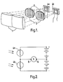
- Figure 1 is a perspective view of the basic optical integers of the apparatus;
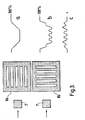
- Figure 2 shows an electrical bridge circuit employed in the apparatus;
- Figure 3 shows masks in the form of so-called "bar gratings" forming part of the sensing means of the apparatus, and the effect on the output signals from said sensing means and from the comparator means by a moving object detected by the apparatus;
- Figure 4 shows a simplified practical electrical circuit of the apparatus;
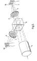
- Figure 5 shows the optical system of a modified form of the apparatus and
- Figure 6 is a fragmentary perspective view of yet another modification of the optical system of the apparatus.
- Referring firstly to Figures 1 to 3, the apparatus comprises twin optical systems in close juxtaposition, each consisting of lens means 1 arranged to produce an image of the scene under surveillance in an
image plane 2. The images so produced will have the same information content and will be of the same brightness. Light passing through the image plane is gathered by means of a lens system 3 and the emerging light falls upon first andsecond devices devices device - If the two
devices output terminals 5 and 6 of the bridge circuit will remain zero at all times when the average illumination of each device is equal. Under these circumstances no potential difference will appear if there is a brightness change of the original scene. - Let us now assume, that in the absence of the "bar gratings" hereinbefore mentioned (Figure 3) the scene being viewed is a plain white background and that a black rectangular object enters the viewed area from one side, traversing the area and leaving from the other side. The average brightness of both images of the scene will change, will become progessively less until the black rectangle is fully within the viewed area, will remain constant at this value until the black rectangle leaves the scene whereupon an increase in brightness to the original value will take place.
- Provided the characteristics of the two optical systems and their transducers are precisely matched, there will have been no electrical signal at the
bridge terminals 5,6. - In the
image plane 2 there are "bar gratings" 8a, 8b having equal bar and slot widths, as shown in Figure 3. However, the longitudinal axes of the bars of one of the two optical systems is at an angle of, say, 90 degrees to the longitudinal axes of the bars of the other optical system. Thus thedevices 4a 4b together with their associatedbar gratings 8a 8b define respectively a first and a second sensing means having different configurations of radiation-sensitive areas. For the unobstructed white scene, the mean value of optical flux reaching each of thedevices 4a 4b is reduced by 50%. - The introduction of a black rectangle 7 as aforesaid now produces an entirely different result. At first there will be a progressive reduction in light falling on both of the
devices 4a 4b but this reduction will not proceed at the same rate for both sensing means, and when the rectangle 7 is fully within the image area, the light on onedevice 4a (i.e. the one associated with the bar grating 8a) will remain constant at a reduced brightness (as shown by curve a) whereas the light on theother device 4b will alternate in strength by virtue of the associated bar grating 8b as shown by curve b, the frequency of the alterations being governed by the dimensions of the grating in relation to the size of the image of the rectangle 7 and its rate of movement across the grating. - As the electrical output signals of the
devices bar gratings 8a, 8b, which will yield a zero output from the-bridge circuit. In fact, this is extremely unlikely to happen because regular geometric shapes and the uniform illumination of the field under surveillance rarely occur in practice. Further, the fact that the shadow of an object generally fails to follow a path identical to that of the object itself would introduce a further complication. - The bars of the
gratings 8a, 8b need not be straight and the slots need not be of uniform width along their lengths, provided that the obscuration is the same for both-of the sensing means. - The output signals from the bridge circuit or other suitable comparator means may be amplified by low frequency alternating current amplifiers, and processed in any of the ways well understood by those skilled in the art.
- There is, however, a further aspect of the invention that suggests that the initial stages of electrical amplification should preferably include, or perform as, a "low pass" filter such that frequency components above a chosen frequency shall not be appreciably amplified. A typical choice for the cut-off frequency is for example about 15Hz to 20Hz.thus permitting the use of light sources operating from an alternating current supply, which, in consequence, have some brightness modulation. This modulation will normally be at twice the supply frequency but may have components at the fundamental frequency.
- Further, such low pass filtering can be arranged to permit the apparatus to be used for viewing a television raster or rasters without disturbance from frame flicker frequencies.
- In practice it can be shown that sharp focus and image perfection is not required in the apparatus described, provided the two sensing means and the associated optical systems are substantially identical, and it has been found possible to employ moulded components in the form of large aperture plastic aspheric lenses. Objects may lie at widely differing distances from the apparatus without detriment to its operation.
- The use of such moulded optical components offers the possibility of constructing the complete optical assembly as a single moulding comprising lenses, masks and cell mounting, thus improving rigidity and reducing manufacturing and assembly costs.
- Further, the
devices separate gratings 8a, 8b and the associated lenses 3. Such a form of apparatus is illustrated in Figure 6. - Experience shows that exact alignment of the two optical paths is unnecessary.
- A further form of optical system is shown in Figure 5. In this system a single imaging lens 1 is employed in conjunction with one of the various forms of "beam splitter" 9 such that two separate and identical images are formed and these are then used in the same manner as for the apparatus described with reference to Figures 1 to 3. A disadvantage of this system is that there is a reduction of about 50% in the intensity of the light or other radiation incident on each of the
devices beam splitter 9. The use of such an arrangement may, however, be justified when it is desired to view a scene with a more specialized and expensive optical system, such as for example a long range telephoto lens. - The simplified diagram of the electrical circuit (Figure 4) of the apparatus shows not only the
devices devices devices resistor 10, dependent on the incident illumination and the lower the illumination the higher the total resistance of the devices and, consequently the lower the current flowing through theresistor 10. This results in a rising voltage across the devices with decreasing illumination and the comparator stage relates this voltage to a pre-set reference voltage. The increasing voltage across the devices, on passing a critical reference value, will cause the comparator to change its output voltage and this signal can be used to trigger an alarm circuit. To render the comparator insensitive to momentary fluctuations of brightness, acapacitor 11 is added to the circuit providing a resistance capacity time constant RC of suitably chosen magnitude. - It will be appreciated that, although the invention has been particularly described with reference to an optical system suitable for the protection of works of art from theft and improper handling, the scope of the invention and its field of application are both very much broader. Thus, the radiation incident on the apparatus may be at a wavelength other than that of light, e.g. of infra-red or ultraviolet, and the change in the pattern of radiation need not necessarily be caused by the movement of an object, but may, as previously indicated, be due to the movement of, or some other change in, an image of such an object.
- Among the possible applications of apparatus according to the invention are those in which, a "warning"or "count" signal is required in the event of a change in a scene under surveillance, whilst others require a signal which represents an "alarm" condition with the necessary low incident of false alarms. The following are some of these applications:
- 1. Protection of individual works of art or exhibits.
- 2. Guarding access to strong rooms, strong room doors, safe deposits and safes.
- 3. General space protection.
- 4. Surveillance of security TV screens to warn of scene changes.
- 5. Watch over sleeping or unconscious patients in medical care.
- 6. "Baby" alarm.
- 7. Surveillance of entries and vehicle areas of car parks, particularly underground or multistorey car parks.
- 8. Remote surveillance of hostage conditions.
- 9. Remote counting of persons.
- 10. Remote counting of vehicles.
- 11. Remote counting of components etc. as in produc tion lines.
- 12. Warning of failure of moving apparatus particularly where conditions are dirty or hazardous, as in chemical plants and nuclear installations. For an application of this type the apparatus of the invention would be used in such a way that an output would be produced when movement ceases rather than when movement is detected. This could be done by causing the signal due to movement to hold open a normally closed switch in an alarm circuit. Cessation of movement would then remove the signal from the switch and thus allow it to close so that the alarm would be sounded.
Claims (7)
1. Apparatus for detecting a change in a pattern of radiation incident on the apparatus, comprising lens means, a first sensing means sensitive to said incident radiation and adapted to give a first output signal characteristic of said pattern, and a second such sensing means, adapted to give a second such output signal, said sensing means having different configurations and/or orientations of radiation-sensitive areas and said lens means together with said sensing means constituting an optical system, are arranged for incidence on said sensing means through said lens means of said radiation, and connected to comparator means in such a way that the latter receives said output signals, the arrangement being such that any change in said pattern of radiation causes a first consequent change by virtue of said different configurations and/or orientations of radiation-sensitive areas, and said comparator means being arranged to supply a signal which is a function of the said differing output signals and hence indicative of a change in said pattern of radiation.
2. Apparatus according to claim 1 wherein each sensing means comprises a combination of a radiation sensitive cell and a mask with the mask interposed between the source of radiation and the cell and including alternate areas which are opaque to and transparent to the radiation.
3. Apparatus according to claim 1 wherein each sensing means is a radiation sensitive cell having at least one sensitive area formed in a predetermined pattern.
4. Apparatus according to any preceding claim including an alarm or indicating device operable upon receipt of the output signal from the comparator.
5. Apparatus according to claim 3 or claim 4 wherein the radiation sensitive cell is light sensitive and wherein the signal outputs from each said cell are substantially equal in a normal undisturbed state.
6. A method of detecting a change in a pattern of radiation emanating from a subject under surveillance comprises causing the said radiation to form or to be so refracted that in the absence of obstruction or of further refraction it would form two essentially identical but spatially displaced images, causing predetermined zones of the radiation which forms or which would form one of the images to impinge on the radiation sensitive member of a first radiation sensitive device and predetermined but different zones of the radiation which forms or.which would form the other image to impinge on the radiation sensitive member of a second radiation sensitive device, the sizes and dispositions ofthe said zones being such that when the article or scene under surveillance and hence the pattern of radiation emanating therefrom is undisturbed, the output signals from each of the radiation sensitive devices remain in a predetermined relationship with each other, but that when there is any change in the pattern of radiation forming the images, the resulting change or changes in the pattern of radiation incident on each of the said radiation sensitive devices will be different for each of the said devices and will cause one or more changes in the relationship between the output signals from them.
7. A method according to claim 6 wherein the resulting change or changes is used to activate an alarm or indicating device.
Applications Claiming Priority (2)
| Application Number | Priority Date | Filing Date | Title |
|---|---|---|---|
| GB8230062 | 1982-10-21 | ||
| GB8230062 | 1982-10-21 |
Publications (2)
| Publication Number | Publication Date |
|---|---|
| EP0107425A2 true EP0107425A2 (en) | 1984-05-02 |
| EP0107425A3 EP0107425A3 (en) | 1984-11-14 |
Family
ID=10533745
Family Applications (1)
| Application Number | Title | Priority Date | Filing Date |
|---|---|---|---|
| EP83306065A Withdrawn EP0107425A3 (en) | 1982-10-21 | 1983-10-06 | Radiation pattern change detection |
Country Status (2)
| Country | Link |
|---|---|
| EP (1) | EP0107425A3 (en) |
| JP (1) | JPS5999278A (en) |
Cited By (4)
| Publication number | Priority date | Publication date | Assignee | Title |
|---|---|---|---|---|
| US7354574B2 (en) | 2002-11-07 | 2008-04-08 | Advanced Ocular Systems Limited | Treatment of ocular disease |
| WO2011158138A1 (en) * | 2010-06-14 | 2011-12-22 | Sony Ericsson Mobile Communications Ab | Spatial detection on an electronic device using optical coding |
| CN107886666A (en) * | 2017-12-14 | 2018-04-06 | 太仓鼎诚电子科技有限公司 | A kind of intelligent Wireless Alarm System |
| CN110197563A (en) * | 2018-02-27 | 2019-09-03 | 河北金锁安防工程股份有限公司 | Three-dimensional auto sleep type anti-theft system |
Families Citing this family (1)
| Publication number | Priority date | Publication date | Assignee | Title |
|---|---|---|---|---|
| JP6182323B2 (en) * | 2013-02-12 | 2017-08-16 | 株式会社メガチップス | Sensor device and sensor application equipment |
Citations (3)
| Publication number | Priority date | Publication date | Assignee | Title |
|---|---|---|---|---|
| US3928843A (en) * | 1974-06-24 | 1975-12-23 | Optical Coating Laboratory Inc | Dual channel infrared intrusion alarm system |
| GB1551541A (en) * | 1977-09-13 | 1979-08-30 | Bloice J A | Infrared intrusion detector system |
| DE2820304A1 (en) * | 1978-05-10 | 1979-11-22 | Joachim Kuhbier | IR detector system - has detectors facing each other, with memory stages to ensure that false signals are avoided |
-
1983
- 1983-10-06 EP EP83306065A patent/EP0107425A3/en not_active Withdrawn
- 1983-10-21 JP JP58198185A patent/JPS5999278A/en active Pending
Patent Citations (3)
| Publication number | Priority date | Publication date | Assignee | Title |
|---|---|---|---|---|
| US3928843A (en) * | 1974-06-24 | 1975-12-23 | Optical Coating Laboratory Inc | Dual channel infrared intrusion alarm system |
| GB1551541A (en) * | 1977-09-13 | 1979-08-30 | Bloice J A | Infrared intrusion detector system |
| DE2820304A1 (en) * | 1978-05-10 | 1979-11-22 | Joachim Kuhbier | IR detector system - has detectors facing each other, with memory stages to ensure that false signals are avoided |
Cited By (4)
| Publication number | Priority date | Publication date | Assignee | Title |
|---|---|---|---|---|
| US7354574B2 (en) | 2002-11-07 | 2008-04-08 | Advanced Ocular Systems Limited | Treatment of ocular disease |
| WO2011158138A1 (en) * | 2010-06-14 | 2011-12-22 | Sony Ericsson Mobile Communications Ab | Spatial detection on an electronic device using optical coding |
| CN107886666A (en) * | 2017-12-14 | 2018-04-06 | 太仓鼎诚电子科技有限公司 | A kind of intelligent Wireless Alarm System |
| CN110197563A (en) * | 2018-02-27 | 2019-09-03 | 河北金锁安防工程股份有限公司 | Three-dimensional auto sleep type anti-theft system |
Also Published As
| Publication number | Publication date |
|---|---|
| JPS5999278A (en) | 1984-06-07 |
| EP0107425A3 (en) | 1984-11-14 |
Similar Documents
| Publication | Publication Date | Title |
|---|---|---|
| US4734585A (en) | Passive infra-red sensor | |
| US4523095A (en) | Radiation detector with asymmetrical pattern | |
| US4342987A (en) | Intruder detection system | |
| US4364030A (en) | Intruder detection system | |
| JP3086406B2 (en) | Passive infrared human body detector | |
| KR100298473B1 (en) | Passive Infrared Detector | |
| US4318089A (en) | Infrared detector system | |
| US5045702A (en) | Infrared intrustion detector | |
| US3829693A (en) | Dual field of view intrusion detector | |
| US5486810A (en) | Infrared detector for detecting motion and fire and an alarm system including the same | |
| JPH0358050B2 (en) | ||
| ATE166737T1 (en) | INTRUSION DETECTOR | |
| JP2001500967A (en) | Passive infrared detector | |
| US4468658A (en) | Simplified intruder detection module | |
| US5420567A (en) | Combination fire/intrusion alarm detectors using active infared elements | |
| US5818337A (en) | Masked passive infrared intrusion detection device and method of operation therefore | |
| US3544988A (en) | Picture motion detection system | |
| US4535240A (en) | Intruder detection | |
| EP0107425A2 (en) | Radiation pattern change detection | |
| GB2411470A (en) | Passive infrared sensor | |
| ATE102726T1 (en) | VIDEO CONTROL FACILITIES. | |
| US8184003B1 (en) | Motion detection and locating apparatus and method | |
| JPS6120827A (en) | Informing device for area monitor | |
| GB2124363A (en) | Intruder detector | |
| JPS62222128A (en) | Passive infrared sensor |
Legal Events
| Date | Code | Title | Description |
|---|---|---|---|
| PUAI | Public reference made under article 153(3) epc to a published international application that has entered the european phase |
Free format text: ORIGINAL CODE: 0009012 |
|
| AK | Designated contracting states |
Designated state(s): DE FR GB IT |
|
| PUAL | Search report despatched |
Free format text: ORIGINAL CODE: 0009013 |
|
| AK | Designated contracting states |
Designated state(s): DE FR GB IT |
|
| STAA | Information on the status of an ep patent application or granted ep patent |
Free format text: STATUS: THE APPLICATION IS DEEMED TO BE WITHDRAWN |
|
| 18D | Application deemed to be withdrawn |
Effective date: 19850715 |
|
| RIN1 | Information on inventor provided before grant (corrected) |
Inventor name: WALTER, DEREK OSCAR |