EP0107408A2 - Verfahren zur Herstellung von Äthanol - Google Patents
Verfahren zur Herstellung von Äthanol Download PDFInfo
- Publication number
- EP0107408A2 EP0107408A2 EP83305949A EP83305949A EP0107408A2 EP 0107408 A2 EP0107408 A2 EP 0107408A2 EP 83305949 A EP83305949 A EP 83305949A EP 83305949 A EP83305949 A EP 83305949A EP 0107408 A2 EP0107408 A2 EP 0107408A2
- Authority
- EP
- European Patent Office
- Prior art keywords
- ethanol
- still
- biomass
- water
- condensate
- Prior art date
- Legal status (The legal status is an assumption and is not a legal conclusion. Google has not performed a legal analysis and makes no representation as to the accuracy of the status listed.)
- Ceased
Links
Images

Classifications
-
- B—PERFORMING OPERATIONS; TRANSPORTING
- B01—PHYSICAL OR CHEMICAL PROCESSES OR APPARATUS IN GENERAL
- B01D—SEPARATION
- B01D3/00—Distillation or related exchange processes in which liquids are contacted with gaseous media, e.g. stripping
- B01D3/001—Processes specially adapted for distillation or rectification of fermented solutions
-
- C—CHEMISTRY; METALLURGY
- C12—BIOCHEMISTRY; BEER; SPIRITS; WINE; VINEGAR; MICROBIOLOGY; ENZYMOLOGY; MUTATION OR GENETIC ENGINEERING
- C12P—FERMENTATION OR ENZYME-USING PROCESSES TO SYNTHESISE A DESIRED CHEMICAL COMPOUND OR COMPOSITION OR TO SEPARATE OPTICAL ISOMERS FROM A RACEMIC MIXTURE
- C12P7/00—Preparation of oxygen-containing organic compounds
- C12P7/02—Preparation of oxygen-containing organic compounds containing a hydroxy group
- C12P7/04—Preparation of oxygen-containing organic compounds containing a hydroxy group acyclic
- C12P7/06—Ethanol, i.e. non-beverage
-
- Y—GENERAL TAGGING OF NEW TECHNOLOGICAL DEVELOPMENTS; GENERAL TAGGING OF CROSS-SECTIONAL TECHNOLOGIES SPANNING OVER SEVERAL SECTIONS OF THE IPC; TECHNICAL SUBJECTS COVERED BY FORMER USPC CROSS-REFERENCE ART COLLECTIONS [XRACs] AND DIGESTS
- Y02—TECHNOLOGIES OR APPLICATIONS FOR MITIGATION OR ADAPTATION AGAINST CLIMATE CHANGE
- Y02E—REDUCTION OF GREENHOUSE GAS [GHG] EMISSIONS, RELATED TO ENERGY GENERATION, TRANSMISSION OR DISTRIBUTION
- Y02E50/00—Technologies for the production of fuel of non-fossil origin
- Y02E50/10—Biofuels, e.g. bio-diesel
-
- Y—GENERAL TAGGING OF NEW TECHNOLOGICAL DEVELOPMENTS; GENERAL TAGGING OF CROSS-SECTIONAL TECHNOLOGIES SPANNING OVER SEVERAL SECTIONS OF THE IPC; TECHNICAL SUBJECTS COVERED BY FORMER USPC CROSS-REFERENCE ART COLLECTIONS [XRACs] AND DIGESTS
- Y02—TECHNOLOGIES OR APPLICATIONS FOR MITIGATION OR ADAPTATION AGAINST CLIMATE CHANGE
- Y02P—CLIMATE CHANGE MITIGATION TECHNOLOGIES IN THE PRODUCTION OR PROCESSING OF GOODS
- Y02P20/00—Technologies relating to chemical industry
- Y02P20/10—Process efficiency
- Y02P20/129—Energy recovery, e.g. by cogeneration, H2recovery or pressure recovery turbines
Definitions
- This invention relates to a process which can employ solar or waste heat for the production of ethanol and dried feed.
- the process of the present invention provides a low scale technology for pasteurization and fermentation of a bianass axnbined with aqueous ethanol removal, preservation of the spent mash into a driec feed, and simple dehydration and distillation of the aqueous ethanol to fuel grade ethanol while recovering the dehydrating agent.
- the present invention may employ siaple solar stills which, excluding an inexpensive plastic cover, may be economically constructed from native materials.
- the entire process may be conducted in only two stills without complex plumbing and instrumentation.
- a dehydrating agent for use in this invention can be made locally from wood ashes. The process is leisurely and may be left unattended. Process stage changes are generally automatic and visibly cliscernable, thus operators need only minimal skills.
- aqueous ethanol mixture obtained from the fermentation process requires further processing to remove water therefrom to increase the ethanol concentration.
- Concentration of ethanol-water mixtures to fuel grade ethanol by distillation is well known. In commercial practice, of the total enrgy used in ethanol production, normally about one-half is used for distillation. Generally, a distillation collumn with 20 to 80 evaporations and condensations (each a so-called theoretical plate) achieves the difficult separation of water and ethanol.
- Distillation techniques are not the only means by which ethanol concentration can be achieved, however.
- Dehydration techniques for ethanol such as the preparation of anhydrws ethanol utilizing anhydrous potassium carbonate have been described as long ago as 1796 (A. Lowita, Crell's Chemical Annals, 1-22 (1796).
- dilute solutions of ethanol in water can be split into an aqueous phase and ethanol phase by adding substantial amounts of certain salts which results in a separation into a heavy bottom liquid layer containing mostly salt in water and a top liquid layer containing ethanol and often same water and salt.
- Ethanol-water separation using complex equipment and high temperature processes to dehydrate a concentrated ethanol-water mixture is disclosed in U.S. Patent No.
- a straight forward economical process combining the processes of pasteurization, fermentation, ethanol removal during and after fermentation, and spent biomass preservation within a single vessel has heretorfore been unknown.
- a practical and economical process for fuel grade or higher grade ethanol production using a chemical dehydrating agent in a low cost still with only one theoretical plate and the ability to use direct solar, low grade or high temperature heat while recovering the dehydrating agent has also heretofore been unknown. It is believed that the present invention provides such processes and hence, uniquely responds to an economic need highlighted by the increasing costs of energy and increasing requirements for practical fuels.
- ethanol is provided by pasteurizing a biomass, fermenting the biamass, and separating an ethanol-water mixture from the bianass which may be further dried to an animal feed, all in a single vessel.
- the ethanol-water mixture may then be subjected to distillation in a second still which contains a dehydrating agent or counter current extraction using the dehydrating agent which is regenerated by removing a portion of water therefrom and reused.
- the stills are suitably heated by solar heat or low grade waste heat, although heat from other sources may alternatively be used.
- Figure 1 illustrates the process steps of the present invention while Figures 2 through 4 illustrate three types of stills which can be used to carry out the process steps of the invention.
- the process of the present invention involves, in a first still, distilling aqueous ethanol from a fermenting or fermented biomass or other ethanol containing material and subsequently dewatering the biomass to provide a dried feed and, in a second still, increasing the ethanol ooncentration of aqueous ethanol by distillation with a dehydrating agent and subseguently dewatering the agent to regenerate it for reuse in the process.
- the process of the present invention is particularly suitable for stills having a single plate by which is meant stills adopted for simple distillation.
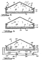
- FIG. 2 is a somewhat schematic vertical cross sectional view of a solar still, indicated generally by the numeral 10, having a base 12 with upwardly extending walls 14 defining a container which holds biomass 16 to be heated or heated and distilled.
- biomass 16 can be any ethanol-containing material.
- Walls 14 are surrounded by insulation 18 which should provide thermal insulation equivalent to about one inch of polystyrene foam.
- Solar still 10 has a light admitting sloping cover 20 which can be transparent plastic film, or alternatively glass, and can have a greenhouse shading curtain 34.
- Cover 20 has four functions. First, cover 20 isolates vapors 22 within interior 24 of still 10 from outside air. Second, cover 20 admits sunlight radiation 26 into interior 24 to heat biomass 16 and base 12.
- cover 20 is in contact with and is cooled by outside air and thus provides a cool surface upon which vapors 22 condense.
- cover 20 slopes from the horizontal, at least 7 degrees, to provide means for collecting condensed liquid 28 which flows on the undersurface of cover 20 down to trough 30 and then exits fran the still.
- still 10 operates in a conventional manner with radiant energy from the sun passing through cover 20 in direction 32 to heat the interior of still 10 but not cover 20 itself, which provides a relatively cool surface relative to the other surfaces of the still for condensation of distilled vapors thereon.
- Cover 20 can be made of plastic or glass, but plastic covers are preferred for reasons of economy. Although glass is water wettable, a plastic film modified to be water wettable on its lower side is most preferred as offering the best performance.
- FIG 3 is a somewhat schematic vertical cross-sectional view of a type of still, indicated generally by the numeral 110, that utilizes bottom heat.
- Bottom heat is supplied to the base of the still and can be low temperature heat found, for example, in liquids or gasses that have been used in cooling industrial processes or electrical generating plants or it may be suplied from solar collectors. In addition, this heat may be partially supplied by brine heated in various processes of this invention. Also, this bottom heat may be sapplied by high grade heat that is generally thought to be high temperature heat such as can be provided by a xmbustian process or the like or a concentrating type solar collector.
- Still 110 has a base 112 with walls 114 extending upwardly therefrom to define a container for bianass 116 to be heated, or heated and distilled. Walls 114 have insulation layer 118 which should provide thermal insulation equivalent to or greater than one inch of polystyrene foam. Still 110 has a sloping cover 120 that can be made of any heat conductive material with a water wettable undersurface. Cover 120 entraps vapars 122 within interior 124 of still 110, thus trappirig heat within the still but cover 120 is itself cooled by outside air and, hence, provides a cool undersurface upon which vapors 122 condense to provide distillate 128 which flows down to trough 130 and exits fran the still.
- Base 112 and bianass 116 are heated by heat fran an external heat source which is transferred thereto through a heat exchanger 132 located within or below base 112 or within biomass 116.
- the heat source for still 110 can be both bottom heat and solar energy.
- cover 120 be transparent to admit sunlight into still 110.
- the above stills are single-effect thermal devices primarily because of the conductiveness of covers 20 and 120.
- each stage of the distillation cycle may be optimized as well as some of the energy recycled. Therefore, the functions of the stills may be segregated such that a separate unit utilizing solar or bottan heat is used to raise the tenperature of the substance to be distilled, the liquid vaporized in an evaporation unit, and the distillate collected ]in a separate condenser device.
- the heat released during condensation may be used to heat additional evaporation units and/or may be used to heat the substances to be distilled. This reuse of heat is commonly enployed and is generally termed milti-effect distillation.
- FIG 4 is a somewhat schematic cross-sectional view of one type of still, indicated generally by the numeral 210 that allows separation and performance optimization of the still functions.
- Still 210 has a base 212 with walls 214 extending upwardly therefrom to. define a container for biomass 216 to be heated, or heated and distilled.
- the base and walls have insulaticn layer 218 which should provide thermal insulation equivalent to or greater than one inch polystyrene foam.
- Solar still 210 has a light transmitting sloping cover 220 which can be one or more layers of a transparent plastic film, or alternatively glass.
- Cover 220 entraps vapors 222 within interior 224 of still 210, thus trapping heat within the still.
- the vapors 222 are moved by air 240 from fan 241 across the still where the vapor 222 and air mixture from the still interior exits the still through conduit 232 and is passed into condenser 242.
- condenser 242 vapors condense providing distillate 243 while air 240 and vapors which did not condense are returned through conduit 234 to the still.
- Air 240 causes circulation inside still 210 to avoid stratification of air and vapors 222 therein.
- the condenser coils 244 are cooled by still feedstock 245 which increases in temperature by absorbing the released heat of condensation fran the vapors 240 and then passes through conduit 248 and enters the still as indicated by arrow 246.
- the still may additionally be equipped with trough 230 which collects distillate 228 from the underside of cover 220.
- Solar stills offer the "least cost" alternative for each of these criteria but deliver variable output dependent upon solar energy received, and lack functionality in certain geographic areas.
- a still utilizing waste heat offers a steady output and is in the lower range of the above criteria but requires, and must be located near, a source of low grade heat.
- a high terperature heat multi-effect still provides the highest output per land area utilized, is more location independent, and offers the possibility of incorporation into existing conventional distillation plants; but is at the high end of the complexity, operational and investment range.
- FIG. 1 A preferred process of the present irmentiay is illustrated schematically in Figure 1.
- a pulverized biomass 16 suitable for fermentation is heated in a still indicated by the numeral 11 which can be of the construction of still 10 or alternatively, still 110 or 210, to between about 65°C up to its boiling point to pasteurize the biaomass and vaporize some of the excess water therein.
- the water is distilled and can optionally be collected as indicated by numeral 31 foar recycling in the process or for other use.
- yeast acting materials are added at numeral 33 to the pasteurized biomass which is heated for fermenting of the bianass.
- the temperature of the bianass is maintained sufficiently high to maintain fermentation which is normally not above 44°C.
- the temperature can be controlled by means of a greenhouse shading curtain 34 for solar still 10 or by adjusting the flow of bottom heat for still 110.
- gaseous ethanol and water separate from the fermenting bianass, condense onto the cool surface of covers 20, 120, or condenser coils 244 and are collected as indicated at numeral 35.
- a second still indicated by the numeral 45 which can be of the same construction as still 10, 110 or 210, can then be employed to increase the ethanol concentration of aqueous ethanol which can be that of numerals 35 and 37 obtained from the first still.
- the second still contains a dehydrating agent 47 of the present invention.
- Aqueous ethanol collected from the fermentation and distillation of the biomass in the first still or alternatively any other aqueous ethanol mixture is added to the dehydrating agent containing still to form an aqueous composition 49.
- the dehydrating agent is hydrophilic in nature and preferably attracts or binds a substantial portion of the water in the ethanol-water mixture, thus increasing the ethanol concentration in the remaining ethanol-water mixture.
- the concentrated ethanol water mixture is then subjected to distillation for further separation to provide a further concentrated ethanol in water mixture as indicated by the numeral 51; or alternatively, if the concentrated ethanol-water mixture separates out as a separate upper phase from the water-oambining agent mixture, then it aey be either distilled or directly withdrawn. However, since a portion of the ethanol-water mixture generally remains in the lower phase which then mist be distilled, directly withdrawing the upper phase has minimal, if any, process advantage.
- the temperature of the concentrated ethanol-water mixture may be raised to at least 30°C up to its boiling point in the still to obtain a gas further enriched in ethanol content which contacts relatively cool surface of covers 20, or 120, or condenser 242 for collection of a distillate.
- the dehydrating agent is regenerated by removing a portion of the water from the brine as indicated by the numeral 57.
- the temperature of the brine can be increased to remove water from the brine. Water so removed may be collected as distillate and optionally may be reused with a biomass for fermentation or any other desired use.
- the dehydrating agent is regenerated and can be recycled to the initial state. In warm arid climates the dewatering process may take place in uncovered open vats 59 or may take place in openponds similar to those used for sea salt proctuction followed by return of the dried dehydrating agent to the still.
- these open ponds also may be constructed as and function as gradient or saturated solar ponds and supply heated brine mixtures to stills utilizing low grade heat or to evaporation devices. It should be appreciated that not all of the water need be removed fran the brine in order to recycle the dehydrating agent, but sufficient water must be removed so that the agent can effectively function to dehydrate the aqueous ethanol.
- Further concentration of the ethanol may be neoessary particularly if the ethanol is to be mixed with gasoline or used in certain chemical processes. If the dehydration agent in use does not provide a phase separation then the ethnol-water mixture 51 may be returned to still 45 containing the reconstituted agent 47 and the distillation, and dewatering steps repeated. However, by using a dehydrating agent that provides for phase separation, further ethanol concentration can take place outside the still in a sinple counter flow extraction tower 63 where the dehydrating agent 61 from the dewatering still or the solar pond enters near the top of the tower and the aqueous ethanol 51 enters near the base of the tower.
- the aqueous ethanol and the dehydrating agent flow counter to each other with a concentrated ethanol water mixture 65 exiting at the top of the tower and the diluted dehydrating agent 67 flowing from near the tower base.
- This diluted brine contains some ethanol and is subjected to distillation in the solar still.
- the concentrated ethanol-water mixture 65 generally contains some concentration of the dehydrating agent.
- the dehydrating agent is preferably removed, especially if the ethanol is to be used as an internal combustion engine fuel or as a solvent. Therefore, preferably the concentrated ethanol-water mixture 65 is distilled in still 69 or the dehydrating agent otherwise removed utilizing ion exchange techniques in ion exchange column 71. Suitable ion exchange apparatus and resins will be appareat to those skilled in the art. For example, if potassium carbonate is used as the dehydrating agent, Rohm and Haas IR120H beads may be used.
- Suitable dehydrating agents for use in the present invention preferentially attract or bind water relative to ethanol.
- the dehydrating agents suitable for use herein are: (1) chemically stable, (2) separate easily from water, (3) are not corrosive under the conditions of use, (4) do not react with ethanol, (5) are not vulnerable to bacterial attack, (6) are highly soluble in water, and (7) are readily available at low cast.
- Such agents include salts which have a solubility in water and which do not react with ethanol under the conditions of use, such as water soluble salts of weak acids.
- Suitable agents include water soluble salts, especially the alkali metal, calcium, barium and magnesium salts of boric acid, carbonic acid, acetic acid, propionic acid, thiosulfuric acid, citric acid, tartaric acid, and mixtures thereof.
- One preferred dehydrating agent is a mineral salt with a solubility in water greater than 30 grams per 100 grams water.
- Other preferred agents include the salts potassium carbonate, potassium sodium carbanate, sodium carbonate, potassium acetate and sodium acetate. These salts, including mixtures thereof, function well in solar stills and low grade heat stills as water binders. As potassium carbonate (“pot ash”) can economically be made fran wood ashes, it is the most preferred salt for use in developing countries.
- the solar still was constructed of galvanized steel and was 25 an square with a basin area of .0625 square meter.
- the front wall measured 2 cm in height and the rear 10 cm.
- the collection trough was adjacent to the front wall.
- the distillate outlet was located below the trough and the solution inlet was located in the rear wall.
- Exterior walls and base were surrounded with 2.5 cm thick polyurethane insulation.
- the still was covered with light transmissible 0.1 mn plastic (polystyrene) film with the underside treated to provide a wettable surface.
- 750 ml of whole bananas were ground in a food pulverizer (with outlet holes measuring 0.5 cm), loaded into the vat, and plaoed in direct sunlight for one day.
- the temperature within the solar vat was adequate for pasteurization at 72 degrees C in several hours. Liquid collected via the solar still collection trough was returned to the still in order to maintain volume at 750 ml.
- Example 1 The product of Example 1 was fermented and simultaneously distilled as follows using a shallow still and solar energy.
- the residual solution (750 ml ground bananas with peel) from Example 1 remained in the same solar still over which a shading curtain commonly used in greenhouse operation was placed to control the solar energy.
- a prepared yeast (dry bread and sherry wine yeasts) suspension (30 ml) was added to the 750 ml banana mixture in the evening when the mixture had cooled to 38 degrees C. Distillation began the next morning.
- Example 2 The product of Example 2 was treated further to yield a dried feed by drying in the same still as in Example 1.
- the residual solution of whole bananas from Example 2 remained in the same shallow still.
- the shading curtain was removed. Drying took place by solar evaporation.
- Ethanol was distilled from a fermented corn mash by use of a solar still in accordance with the following.
- Industrially fermented corn mash with an ethanol content of approximately 8 percent was used.
- the solar still was constructed of a 2.54 an thick wooden base placed over 2.54 an thick polyurethane insulation.
- the wood sides were 10 an high with two opposing sides containing 1.26 an aluminum channel condensation collection troughs mounted at a 4 percent slope.
- the basin liquid reservoir (0.836 square meters) was 0.159 an alumimm sheeting aovered with a heat absorbent black pigmented paint.
- Solution inlets and drains were constructed over the basis sideboards with a side inclination of 50 degrees.
- the Iight transmissible cover was 0.1 mm PVF film (polyvinyl fluoride). Eight liters (7,504 grams) of corn mash was loaded into the still early one morning. Distillate appeared in the collection troughs that afternoon.
- Fuel grade ethanol was produced from dilute ethanol using a solar still containing potash.
- the potash used was industrial grade 99 percent R 2 CO 3 .
- the solar still was constructed of galvanized steel and measured one meter square. The slope of the solar roof was 12 degrees with the rear wall 21 an high and the front 3 an high. A collection trough 2 cm wide was positioned parallel to the front wall and was provided with four connected outlets. Still loading was accomplished by means of a rear inlet connected to a distribution pipe.
- the basin was coated with a heat absorbent black paint while all exterior metal surfaces were covered with 2.54 cm polyurethane foam insulation.
- the light transmissible cover was a 0.318 an standard double strength window glass.
- Outputs collected were as follows: A total of 99.4 percent of the ethanol was recovered with a rise in concentration from 11.8 to 58.8 percent. At point “A” 95.8 percent of the ethanol had been removed at a 75 percent concentration and at point “B", 98.6 percent at a 70 percent concentration.
- Example 6 The potash solution used in Example 6 was recycled as follows. The residual from Example 6 (a mixture of 10.4 liters of water and 9.8 kilograms of potash) was left in the same shallow still. Output of the still was allowed to continue to reduce the potash solution to the original concentration which contained 4 liters water. The water removed is shown below:
- Potash was recrystallized from a brine solution using a solar still as follows.
- the residual solution from Example 7 (a mixture of 4.16 liters water and 9.8 kilograms potash) was left in the sane shallow still and solar dried. Over a four day period, an additional 1.9 liters of water was removed.
- the resultant solar dried potash (large crystals and chunks) was found to contain 19% water corresponding to K 2 CO 3 ⁇ 1.8 H 2 0.
- Evaporation rates of a solar still and a solar evaporation pond were compared.
- the still was constructed of stainless steel surrounded by 2.5 an foam insulation.
- the still was lined with a 7 mil black plastic film and measured 50 by 25 cm with a surface area of .125 square meter.
- the still cover was double strength window glass.
- the pond was built of 2.5 cm foam insulation with the same black plastic film liner and measured 30 an by 24 cm giving a surface area of .072 square meter.
- the still was loaded with 3 liters of a 2 to 1 volume ratio of water and potassium carbonate and the pond contained 7 liters of the same mixture. The still and pond were replenished each day.
- a comparison of concentrations of ethanol distillate were made using different concentrations of potash and water.
- the solar still was made of stainless steel and measured 500 by 250 an.
- the slope of the roof was 15 degrees.
- a 3 an wide collection through was positioned parallel to the front wall and provided with two connected outlets.
- Black polyethlene film of 0.2 mn thickness lined the basin and polyurethane foam of 2.54 an thickness insulated all exterior metal surfaces.
- the light transmissible cover was single-strength window glass.
- Example 7 An ethanol solution was concentrated by phase separation using solar dried crystalline potash of Example 8 which was subsequently reconstituted in the same still in accordance with the following.
- the 12 kilograms of solar dried potash crystals of Exanple 8 were left in the same solar still.
- Twelve (12) liters of a 10 percent ethanol-water solution were added and the mixture allowed to stand in the sun for one day with the collection trough cock closed.
- the mixture temperature increased from 20 degrees to 58 degrees C thereby increasing the solubility of the potassium carbonate mixture. That evening the concentrated ethanol solution that was layered above the potash-water solution was drained through the side of the still.
- Some overflow of the water-potash mixture was also collected and was separated from the ethanol water mixture by means of a separation funnel and returned to the still.
- the potash solution (including some 2.3 kilograms of potash crystals not in solution) was reconstituted as in Example 7.
- the ethanol-water solution measured 1.464 liters and contained 81 percent ethanol by volume and 19 percent water representing a 98.8 percent recovery of the initial ethanol.
- 46.3 grams of the 81 percent ethanol-water solution was evaluated and found to have a residue potassium carbonate content of about 300 ppm. No potassium carbonate was found in a 200 ml sample of the 81 percent ethanol-water solution which had been solar distilled.
- Example 6 A portion of the distillate from Example 6 (58.8 volumes percent or 53 percent by weight) was subjected to counter flow extraction to further concentrate the ethanol.
- the extractor consisted of four (4) 250 ml beakers (equal to an extractor of four stages) resting on stirring devices. Each beaker contained 22 grams potash and 20 grams water. 21.2 grams ethanol mixed with 18.8 grams water was added to the first beaker. The resultant top layer was removed and passed to the second beaker, with the sequence repeated until the top phase from the third beaker was placed in the fourth beaker. In order to achieve approximate steady state conditions, the above sequence was cycled four times by discarding the lower phase contents of the first beaker and adding a fourth beaker each cycle.
- a 3.1 wt% ethanol commercial light beer was distilled in a simple one plate still containing potash. 350 ml light beer and 320 ml dry potash were used.
- a still having substantially one theoretical plate and providing no reflux, was assembled from a conical-shaped glass distillation pot (Erlenmeyer type) with a side arm. The still was insulated with metal foil to prevent re-evaporation of the distillate. The arm was connected to a simple water cooled condenser-collector tube. The still was heated with either hot water or hot oil as required. The potash was placed in the still. After mixing in the beer the still was heated.
- the output totaled 12 g liquid and contained slightly less than 11 g ethanol or a 91 wt% ethanol concentration.
- a single plate distillation of 91 percent ethanol was carried out as follows to concentrate the ethanol in a simple single plate still containing potash and then recover the water from the potash.
- the materials used were 31.3 g water, 313.0 g ethanol (91 wt%, 94 vol% ethanol) and 125.2 g K 2 CO 3 .
- the still used was that of Example 12.
- the ethanol mixture was then added to the still and the temperature remained at 77.8°C for the ethanol distillation and then raised to 105 degrees C for the water distillation.
- the initial output was 324.1 g ethanol-water mixture containing 312.8 g ethanol (96.5 percent by weight) indicating a 99.9 percent recovery of the initial ethanol.
- the dried potash was found to weigh 121.8 g.
Landscapes
- Chemical & Material Sciences (AREA)
- Organic Chemistry (AREA)
- Wood Science & Technology (AREA)
- Engineering & Computer Science (AREA)
- Chemical Kinetics & Catalysis (AREA)
- Zoology (AREA)
- Life Sciences & Earth Sciences (AREA)
- Microbiology (AREA)
- Biotechnology (AREA)
- General Chemical & Material Sciences (AREA)
- Health & Medical Sciences (AREA)
- Biochemistry (AREA)
- Bioinformatics & Cheminformatics (AREA)
- General Engineering & Computer Science (AREA)
- General Health & Medical Sciences (AREA)
- Genetics & Genomics (AREA)
- Preparation Of Compounds By Using Micro-Organisms (AREA)
- Organic Low-Molecular-Weight Compounds And Preparation Thereof (AREA)
Applications Claiming Priority (4)
| Application Number | Priority Date | Filing Date | Title |
|---|---|---|---|
| US43078282A | 1982-09-30 | 1982-09-30 | |
| US430782 | 1982-09-30 | ||
| US53062183A | 1983-09-12 | 1983-09-12 | |
| US530621 | 1983-09-12 |
Publications (2)
| Publication Number | Publication Date |
|---|---|
| EP0107408A2 true EP0107408A2 (de) | 1984-05-02 |
| EP0107408A3 EP0107408A3 (de) | 1985-07-03 |
Family
ID=27028750
Family Applications (1)
| Application Number | Title | Priority Date | Filing Date |
|---|---|---|---|
| EP83305949A Ceased EP0107408A3 (de) | 1982-09-30 | 1983-09-30 | Verfahren zur Herstellung von Äthanol |
Country Status (4)
| Country | Link |
|---|---|
| EP (1) | EP0107408A3 (de) |
| AU (1) | AU1936283A (de) |
| BR (1) | BR8305508A (de) |
| ES (1) | ES526031A0 (de) |
Family Cites Families (7)
| Publication number | Priority date | Publication date | Assignee | Title |
|---|---|---|---|---|
| GB189136A (en) * | 1921-11-15 | 1923-10-04 | Barbet & Fils & Cie E | Improved continuous process and apparatus for the production of large quantities of absolute alcohol |
| FR728019A (fr) * | 1931-02-04 | 1932-06-28 | Degussa | Procédé et appareil pour l'épuration et la déshydratation de l'alcool éthylique et de mélanges de liquides organiques contenant de l'alcool éthylique |
| FR986875A (fr) * | 1949-03-24 | 1951-08-06 | Soc D Ets Barbet | Procédé et appareil pour la production de rhum ou d'eaux-de-vie |
| US4345974A (en) * | 1980-09-15 | 1982-08-24 | Mccarthy Walton W | Solar process |
| US4347321A (en) * | 1980-10-07 | 1982-08-31 | Bio-Systems Research, Inc. | Method and apparatus for producing alcohol |
| US4371623A (en) * | 1981-02-09 | 1983-02-01 | William N. Durkin | Solar still |
| US4395488A (en) * | 1981-09-14 | 1983-07-26 | Rowe Delton J | Drive-through pit production of ethanol |
-
1983
- 1983-09-22 AU AU19362/83A patent/AU1936283A/en not_active Abandoned
- 1983-09-28 ES ES526031A patent/ES526031A0/es active Granted
- 1983-09-30 EP EP83305949A patent/EP0107408A3/de not_active Ceased
- 1983-09-30 BR BR8305508A patent/BR8305508A/pt unknown
Also Published As
| Publication number | Publication date |
|---|---|
| BR8305508A (pt) | 1984-05-15 |
| ES8603370A1 (es) | 1985-12-16 |
| EP0107408A3 (de) | 1985-07-03 |
| ES526031A0 (es) | 1985-12-16 |
| AU1936283A (en) | 1984-04-05 |
Similar Documents
| Publication | Publication Date | Title |
|---|---|---|
| Maiorella et al. | Alcohol production and recovery | |
| US4345973A (en) | Vapor phase dehydration of aqueous alcohol mixtures | |
| de Souza Dias et al. | Sugarcane processing for ethanol and sugar in Brazil | |
| US4564595A (en) | Alcohol manufacturing process | |
| US4305790A (en) | Multiple effect distillation method and apparatus | |
| US20170298393A1 (en) | Processes and Systems for Alcohol Production and Recovery | |
| BR112019018873A2 (pt) | processo para produção de etanol combustível com o uso de amido de milho como matéria-prima. | |
| US4822737A (en) | Process for producing ethanol by fermentation | |
| JP2013514815A (ja) | アルコール回収および蒸留廃液副生成物の濃縮システムおよび方法 | |
| CN102482689A (zh) | 从稀水溶液回收高级醇 | |
| CA1140873B (en) | Production of volatile organic compound by continuous fermentation | |
| US4440861A (en) | Solar apparatus and process | |
| EP0107408A2 (de) | Verfahren zur Herstellung von Äthanol | |
| US4345974A (en) | Solar process | |
| RU2391407C2 (ru) | Способ и установка для получения смеси этанола и воды | |
| US4345972A (en) | Alcohol recovery process | |
| CN101293862A (zh) | 杀虫单离心母液制备高含量杀虫单及杀虫双的方法 | |
| Koutinas et al. | Continuous potable alcohol production by immobilized Zymomonas mobilis on γ‐alumina pellets | |
| US4487832A (en) | Process for making n-butyl butyrate | |
| Modl | Jilin fuel ethanol plant | |
| RU2041219C1 (ru) | Способ переработки растительного сырья для получения фурфурола в спиртово-дрожжевом производстве | |
| EP0081211A2 (de) | Konzentrierung von organischen Chemikalien aus verdünnten wässrigen Lösungen | |
| CA1127984A (en) | Method for the recovery of a volatile compound by fermentation of a carbohydrate material | |
| Wright | A Practical Handbook on the Distillation of Alcohol from Farm Products, Including the Processes of Malting... Etc: With Chapters on Alcoholometry and the De-naturing of Alcohol... | |
| SU1225841A1 (ru) | Непрерывный способ получени фурфурола |
Legal Events
| Date | Code | Title | Description |
|---|---|---|---|
| PUAI | Public reference made under article 153(3) epc to a published international application that has entered the european phase |
Free format text: ORIGINAL CODE: 0009012 |
|
| AK | Designated contracting states |
Designated state(s): FR GB IT |
|
| PUAL | Search report despatched |
Free format text: ORIGINAL CODE: 0009013 |
|
| AK | Designated contracting states |
Designated state(s): FR GB IT |
|
| 17P | Request for examination filed |
Effective date: 19851116 |
|
| 17Q | First examination report despatched |
Effective date: 19860915 |
|
| ITF | It: translation for a ep patent filed | ||
| STAA | Information on the status of an ep patent application or granted ep patent |
Free format text: STATUS: THE APPLICATION HAS BEEN REFUSED |
|
| 18R | Application refused |
Effective date: 19880429 |