EP0107294B1 - Reception signal processing apparatus in nuclear magnetic resonance diagnostic apparatus - Google Patents
Reception signal processing apparatus in nuclear magnetic resonance diagnostic apparatus Download PDFInfo
- Publication number
- EP0107294B1 EP0107294B1 EP83304971A EP83304971A EP0107294B1 EP 0107294 B1 EP0107294 B1 EP 0107294B1 EP 83304971 A EP83304971 A EP 83304971A EP 83304971 A EP83304971 A EP 83304971A EP 0107294 B1 EP0107294 B1 EP 0107294B1
- Authority
- EP
- European Patent Office
- Prior art keywords
- magnetic resonance
- nuclear magnetic
- phase
- signals
- reception signal
- Prior art date
- Legal status (The legal status is an assumption and is not a legal conclusion. Google has not performed a legal analysis and makes no representation as to the accuracy of the status listed.)
- Expired
Links
Images


Classifications
-
- G—PHYSICS
- G01—MEASURING; TESTING
- G01R—MEASURING ELECTRIC VARIABLES; MEASURING MAGNETIC VARIABLES
- G01R33/00—Arrangements or instruments for measuring magnetic variables
- G01R33/20—Arrangements or instruments for measuring magnetic variables involving magnetic resonance
- G01R33/28—Details of apparatus provided for in groups G01R33/44 - G01R33/64
- G01R33/32—Excitation or detection systems, e.g. using radio frequency signals
- G01R33/36—Electrical details, e.g. matching or coupling of the coil to the receiver
- G01R33/3621—NMR receivers or demodulators, e.g. preamplifiers, means for frequency modulation of the MR signal using a digital down converter, means for analog to digital conversion [ADC] or for filtering or processing of the MR signal such as bandpass filtering, resampling, decimation or interpolation
-
- G—PHYSICS
- G01—MEASURING; TESTING
- G01R—MEASURING ELECTRIC VARIABLES; MEASURING MAGNETIC VARIABLES
- G01R33/00—Arrangements or instruments for measuring magnetic variables
- G01R33/20—Arrangements or instruments for measuring magnetic variables involving magnetic resonance
- G01R33/44—Arrangements or instruments for measuring magnetic variables involving magnetic resonance using nuclear magnetic resonance [NMR]
- G01R33/48—NMR imaging systems
- G01R33/54—Signal processing systems, e.g. using pulse sequences ; Generation or control of pulse sequences; Operator console
Definitions
- This invention relates to nuclear magnetic resonance diagnostic apparatus to display as an image the distribution of the spin density or relaxation time of specified atomic nuclei existing in an object utilizing nuclear magnetic resonance (NMR) phenomena, more particularly to reception signal processing apparatus to process the received NMR signals at the preliminary stage of image formation.
- NMR nuclear magnetic resonance
- Nuclear magnetic resonance diagnostic apparatus developed recently are constructed to phase- demodulate the detected NMR signals with two reference waves having a 90° phase difference for using their frequency and phase information for image reconstruction.
- NMR signals F'c(t) and F's(t) obtained by modulation have relationships, which are represented by the first and second formulas, respectively, with the frequency spectrum p(w) which reflects the spin density or relaxation time of the atomic nuclei.
- p(w) is the frequency spectrum of a reception signal (which corresponds to the spin density and relaxation time of an atomic nucleus);
- Japanese Patent Publication No. JP-A-56-14146 describes a reception signal processing apparatus in nuclear magnetic resonance diagnostic apparatus to display as an image the distribution of the spin density or relaxation time of specified atomic nuclei existing in an object utilising nuclear magnetic resonance phenomena, the reception signal processing apparatus comprising:
- the present invention provides reception signal processing apparatus in nuclear magnetic resonance diagnostic apparatus to display as an image the distribution of the spin density or relaxation time of specified atomic nuclei existing in an object utilizing nuclear magnetic resonance phenomena, the reception signal processing apparatus comprising:
- NMR signals observed in fact are represented by the first and second formulas as described above. Developing the first and second formulas, they are as follows: Here,
- phase reference ⁇ In order to reduce the distortion of the frequency spectrum p(w) due to the phase difference ⁇ between the NMR signal and the reference wave, the value of phase reference ⁇ must be known.
- F'c(t) 2 +F's(t) 2 represents a value which is proportional to the magnitude of magnetization which induces an NMR signal.
- formulas (5) and (6) are obtained from the formulas (1') and (2'), respectively:
- Fc'(t) and Fs'(t) at that time are respectively: also,
- phase difference ⁇ can be found in accordance with the following formula (14) on the basis of Fc'(t) and Fs'(t): where t max is the time when F'c(t) 2 +Fs'(t) 2 is maximum.
- the frequency spectrum p(w) is represented as follows: where Pr'(w) and Pi'(w) represent a real part and imaginary part of the complex Fourier-transformation.
- the frequency spectrum may be obtained by correcting the phase difference by the following three methods.
- Fc(t) and Fs(t) are found on the basis of using formula (14) to determine ⁇ and using the observed signals Fc'(t) and Fs'(t), and then applying these in accordance with the formulas (15) and (16).
- the frequency spectrum is found by Fourier-transforming that Fc(t) and Fs(t).
- the observed signals Fc'(t) and Fs'(t) are Fourier transformed after transformation into complex space coordinate system. And the frequency spectrum is found by substituting ⁇ which is found with formula (14) into the real part of the formula (20).
- the observed signals Fc'(t) and Fs'(t) are Fourier transformed after transformation into complex space coordinate system. And the frequency spectrum is found by substituting ⁇ which is found with the imaginary part of formula (20) into the real part thereof.
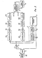
- an object 1 is placed in the static magnetic field Ho and also in the field of a transmission and reception signal coil 2 which generates a magnetic field perpendicular to the static magnetic field Ho.
- a tuner 3 operates to select an electromagnetic wave of specified frequency from the electromagnetic signal issued from transmission system 4, to be applied as an excitation pulse to coil 2, the frequency being the resonant frequency of the specified atomic nucleus such as hydrogen within the object 1.
- Amplifier 5 amplifies the NMR signal received by the coil 2 to deliver it to two phase demodulators 6A and 6B.
- a reference signal generator 7 being provided with a phase shifter 7A and a 90° phase converter 7B, generates two kinds of reference waves, each having the same frequency as the NMR signal but with phases differing from each other by 90°. The generated reference waves are supplied to the phase demodulators 6A and 6B, respectively.
- the two phase demodulators 6A and 6B phase demodulate the NMR signal with the reference wave to separately generate two analog signals Fc'(t) and Fs'(t), respectively.
- the separated signals Fc'(t) and Fs'(t) are amplified by amplifiers 8A and 8B, the high frequency component of the signals are blocked by low pass filters 9A and 9B and the signals are digitalized by analog-to-digital (A/D) converters 10A and 10B, respectively.
- A/D analog-to-digital converters
- This phase correction processor 11 is a digital calculation apparatus for finding the phase difference between the reference wave and NMR signal to produce the frequency spectrum without influence due to the phase difference. That is, the phase correction processor 11 performs a calculation in compliance with one of the routines as shown in Figs. 4 to 6 for phase correction in accordance with one of the above described three methods, thereby producing projection data p(i) to an image processor 12.
- Fc' (i max) and Fs' (i max) at the time when Fc'(i) 2 +Fs'(i) 2 assumes the maximum value Max are found and inputted to the phase correction processor 11.
- sin ⁇ is calculated based on values of Fs'(i max) and Max while cos ⁇ is calculated based on values of Fc'(i max) and Max.
- Fc(i) and Fs(i) are found based on values of cos ⁇ , sin ⁇ , Fc'(i) and Fs'(i) in accordance with the formulas (15) and (16).
- NFFT is the number of times of Fourier transformation, N being the number of calculations. It is thereby possible to obtain the data of Fc(1), Fc(2), ..., Fc(N), and Fs(1), Fs(2), ..., Fs(N). Fc(i) and Fs(i) are transformed to the frequency spectrum p(i) which is not influenced by ⁇ after Fouriertransformation.
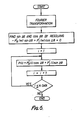
- the routine shown in Fig. 4 corresponds to the No. 1 method which has been described above.
- the routine of Fig. 5 corresponds to the No. 2 method above. That is, sin ⁇ and cos ⁇ are found based on values of Fc'(i) and Fs'(i) which are inputted to the phase correction processor 11, in a routine similar to that of Fig. 4.
- Fc'(i) and Fs'(i) are Fourier transformed after conversion to complex space coordinate system, p(i) is found in accordance with the real part of formula (20) based on the obtained values of Pr'(i), Pi'(i), cos ⁇ and sin ⁇ .
- NDATA is the number of acquisition times of the signals, and if there are N calculations, it is possible to obtain p(1), p(2), ..., p(N) as the frequency spectrum.
- the routine of Fig. 6 corresponds to the No. 3 method described above.
- Fc'(i) and Fs'(i) are Fourier transformed in compliance with formulas (18) and (19) after conversion to complex space coordinate system.
- Sin ⁇ and cos ⁇ next are found by putting the imaginary part of the formula (20) to zero.
- p(i) is found in accordance with the real part of the formula (20) based on values of Pr'(i) and Pi'(i) as obtained by Fourier transformation and the obtained values of sin ⁇ and cos ⁇ .
- the two signals are phase corrected by any one of the above described routines and are delivered to an image processing apparatus 12 to perform the imaging procedure as to spin density and relaxation time of the specified atomic nucleus such as hydrogen.
Description
- This invention relates to nuclear magnetic resonance diagnostic apparatus to display as an image the distribution of the spin density or relaxation time of specified atomic nuclei existing in an object utilizing nuclear magnetic resonance (NMR) phenomena, more particularly to reception signal processing apparatus to process the received NMR signals at the preliminary stage of image formation.
- Nuclear magnetic resonance diagnostic apparatus developed recently are constructed to phase- demodulate the detected NMR signals with two reference waves having a 90° phase difference for using their frequency and phase information for image reconstruction.
- Two kinds of NMR signals F'c(t) and F's(t) obtained by modulation have relationships, which are represented by the first and second formulas, respectively, with the frequency spectrum p(w) which reflects the spin density or relaxation time of the atomic nuclei.


- w is angular frequency
- t is time; and
- A0 is the phase difference between a reference wave and reception signal at a demodulation time.
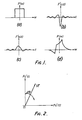
- However, if the two signals of the formulas above are Fourier transformed, for example, p(w) as shown in Figure 1(d) appears as F'c(t) and F's(t) shown in Figures 1(b) and (c) respectively. It is impossible to obtain p(w) as shown in Figure 1 (a) necessary to form an image. This is why the phase difference Δθ exists in the first and second formulas because both phases of the reference wave and the NMR signals are necessarily not in coincidence at the demodulation time.
- Consequently, in the conventional NMR apparatus, its operator has to manually adjust the phase relation between the reference wave and the NMR signal at the demodulation time to be coincident with each other, while observing the frequency spectrum after Fourier transformation. However, with such a manual adjustment, individual differences appear in the result and it takes an extremely long time for the adjustment.
- Japanese Patent Publication No. JP-A-56-14146 describes a reception signal processing apparatus in nuclear magnetic resonance diagnostic apparatus to display as an image the distribution of the spin density or relaxation time of specified atomic nuclei existing in an object utilising nuclear magnetic resonance phenomena, the reception signal processing apparatus comprising:
- means (8,9) for phase demodulating a nuclear magnetic resonance signal evoked by nuclear magnetic resonance phenomena in accordance with two reference waves the phase (0°, 90°) of which are different from one another by 90°;
- means (11,12) for digitalizing the separated two signals obtained by said phase demodulating means (8, 9); and
- phase correction processing means (13,14) for automatically correcting the phase difference between the reference waves and nuclear magnetic resonance signal for producing a frqeuency spectrum by processing said digitalized signals.
- It is an object of this invention to provide improved reception signal processing apparatus in nuclear magnetic resonance (NMR) diagnostic apparatus to correct automatically the influence due to the phase difference between the reference waves and the NMR signal when phase demodulating an NMR signal in accordance with two reference waves which have the same resonance frequency as the resonance signal and are different from one another by a 90° phase shift.
- Accordingly the present invention provides reception signal processing apparatus in nuclear magnetic resonance diagnostic apparatus to display as an image the distribution of the spin density or relaxation time of specified atomic nuclei existing in an object utilizing nuclear magnetic resonance phenomena, the reception signal processing apparatus comprising:
- means for phase demodulating a nuclear magnetic resonance signal evoked by nuclear magnetic resonance phenomena in accordance with two reference waves the phases of which are different from one another by 90°;
- means for digitalizing the separated two signals Fc'(t) and Fs'(t) obtained by said phase demodulating means whereby t is time; and
- phase correction processing means for automatically correcting the phase difference between the reference waves and nuclear magnetic resonance signal for producing a frequency spectrum by processing said digitalized signals,
- characterised in that said phase correction processing means comprises:
- means for determining the value tmax of the time t when the function [Fc'(t)]2+[Fs'(t)]2 reaches a maximum value;
- and means for calculating the phase correction angle as

- Figure 1(a) is a wave form chart illustrating the frequency spectrum of an NMR signal;
- Figures 1(b) and (c) are wave form charts illustrating two kinds of frequency spectra as observed at the time when the reference wave and NMR signal are different in phase from each other at the demodulation time;
- Fig. 1(d) is a wave form chart illustrating the frequency spectrum obtained by Fourier transformation of the two kinds of NMR signals;
- Fig. 2 is a graphical representation illustrating a relationship between the magnetization victor and the two kinds of NMR signals;
- Fig. 3 is a schematic block diagram illustrating the construction of an embodiment of this invention; and
- Figs. 4 to 6 are flow charts illustrating the different methods of phase correction which can be carried out by the apparatus according to the invention.
- NMR signals observed in fact are represented by the first and second formulas as described above. Developing the first and second formulas, they are as follows:


- In order to reduce the distortion of the frequency spectrum p(w) due to the phase difference Δθ between the NMR signal and the reference wave, the value of phase reference Δθ must be known.
- There are two kinds of methods for finding the value of the phase difference.
- In accordance with the first method, F'c(t)2+F's(t)2 represents a value which is proportional to the magnitude of magnetization which induces an NMR signal. Here, the following formulas (5) and (6) are obtained from the formulas (1') and (2'), respectively:


- Therefore,

-


- Consequently, Fc(t)2+Fs(t)2 and Fc'(t)2+Fs'(t)2 are maximum at t=0, Fc'(t) and Fs'(t) at that time are respectively:


- There is diagramatically illustrated in Fig. 2 the relationship among the above formulas (11), (12) and (13).
- Consequently, the phase difference Δθ can be found in accordance with the following formula (14) on the basis of Fc'(t) and Fs'(t):

- In accordance with the second method resolving the aforementioned formu)as(1') and (2') for Fc(t) and Fs(t):


- Representing Fc(t) and Fs(t) in imaginary space coordinates, they are:

- Here, if assuming F(t)=Fc(t)+j Fs(t) and F'(t)=Fc'(t)+j Fs'(t), the formula (17) is:

- By Fourier-transforming the formula (18), the frequency spectrum p(w) is represented as follows:

- Also, transforming the formula (19), the following formula is obtained:

- Since P(w) is a real function, the imaginary part in the formula (20) comes to zero. Accordingly, it is possible to find Δθ utilizing -Pr'(w) sin Δθ+Pi'(w) cos Δθ=0.
- By using Δθ found by one of the above methods, the frequency spectrum may be obtained by correcting the phase difference by the following three methods.
- First, Fc(t) and Fs(t) are found on the basis of using formula (14) to determine Δθ and using the observed signals Fc'(t) and Fs'(t), and then applying these in accordance with the formulas (15) and (16). Next, the frequency spectrum is found by Fourier-transforming that Fc(t) and Fs(t).
- The observed signals Fc'(t) and Fs'(t) are Fourier transformed after transformation into complex space coordinate system. And the frequency spectrum is found by substituting θθ which is found with formula (14) into the real part of the formula (20).
- The observed signals Fc'(t) and Fs'(t) are Fourier transformed after transformation into complex space coordinate system. And the frequency spectrum is found by substituting Δθ which is found with the imaginary part of formula (20) into the real part thereof.
- One embodiment of the invention in which the aforementioned principle is embodied will now be explained referring to the Figures.
- In Fig. 3, an
object 1 is placed in the static magnetic field Ho and also in the field of a transmission andreception signal coil 2 which generates a magnetic field perpendicular to the static magnetic field Ho. Atuner 3 operates to select an electromagnetic wave of specified frequency from the electromagnetic signal issued from transmission system 4, to be applied as an excitation pulse tocoil 2, the frequency being the resonant frequency of the specified atomic nucleus such as hydrogen within theobject 1.Amplifier 5 amplifies the NMR signal received by thecoil 2 to deliver it to twophase demodulators phase shifter 7A and a 90°phase converter 7B, generates two kinds of reference waves, each having the same frequency as the NMR signal but with phases differing from each other by 90°. The generated reference waves are supplied to thephase demodulators - The two
phase demodulators amplifiers low pass filters converters phase correction processor 11. - This
phase correction processor 11 is a digital calculation apparatus for finding the phase difference between the reference wave and NMR signal to produce the frequency spectrum without influence due to the phase difference. That is, thephase correction processor 11 performs a calculation in compliance with one of the routines as shown in Figs. 4 to 6 for phase correction in accordance with one of the above described three methods, thereby producing projection data p(i) to animage processor 12. - Referring first to the routine of Fig. 4, Fc' (i max) and Fs' (i max), at the time when Fc'(i)2+Fs'(i)2 assumes the maximum value Max are found and inputted to the
phase correction processor 11. Next, sin Δθ is calculated based on values of Fs'(i max) and Max while cos Δθ is calculated based on values of Fc'(i max) and Max. Fc(i) and Fs(i) are found based on values of cos Δθ, sin Δθ, Fc'(i) and Fs'(i) in accordance with the formulas (15) and (16). - NFFT is the number of times of Fourier transformation, N being the number of calculations. It is thereby possible to obtain the data of Fc(1), Fc(2), ..., Fc(N), and Fs(1), Fs(2), ..., Fs(N). Fc(i) and Fs(i) are transformed to the frequency spectrum p(i) which is not influenced by Δθ after Fouriertransformation. The routine shown in Fig. 4 corresponds to the No. 1 method which has been described above.
- The routine of Fig. 5 corresponds to the No. 2 method above. That is, sin Δθ and cos Δθ are found based on values of Fc'(i) and Fs'(i) which are inputted to the
phase correction processor 11, in a routine similar to that of Fig. 4. Next, Fc'(i) and Fs'(i) are Fourier transformed after conversion to complex space coordinate system, p(i) is found in accordance with the real part of formula (20) based on the obtained values of Pr'(i), Pi'(i), cos Δθ and sin Δθ. NDATA is the number of acquisition times of the signals, and if there are N calculations, it is possible to obtain p(1), p(2), ..., p(N) as the frequency spectrum. - The routine of Fig. 6 corresponds to the No. 3 method described above. Fc'(i) and Fs'(i) are Fourier transformed in compliance with formulas (18) and (19) after conversion to complex space coordinate system. Sin Δθ and cos Δθ next are found by putting the imaginary part of the formula (20) to zero. p(i) is found in accordance with the real part of the formula (20) based on values of Pr'(i) and Pi'(i) as obtained by Fourier transformation and the obtained values of sin Δθ and cos Δθ.
- The two signals are phase corrected by any one of the above described routines and are delivered to an
image processing apparatus 12 to perform the imaging procedure as to spin density and relaxation time of the specified atomic nucleus such as hydrogen. - According to the construction as described above in detail, it is possible to automatically correct the influence due to the phase difference between the reference wave and NMR signal, to obtain an accurate frequency spectrum which is produced by demodulating the NMR signal with two reference waves differing from each other by 90° in phase and Fourier transforming the digitalized two signals Fc'(i) and Fs'(i) or two signals Fc(i) and Fs(i).
- It will be apparent, to those skilled in the art, that modifications and variations can be made in the preferred embodiment disclosed herein without departing from the scope of the invention.
Claims (2)

Applications Claiming Priority (2)
| Application Number | Priority Date | Filing Date | Title |
|---|---|---|---|
| JP57149773A JPS5938636A (en) | 1982-08-28 | 1982-08-28 | Nuclear magnetic resonance apparatus |
| JP149773/82 | 1982-08-28 |
Publications (3)
| Publication Number | Publication Date |
|---|---|
| EP0107294A2 EP0107294A2 (en) | 1984-05-02 |
| EP0107294A3 EP0107294A3 (en) | 1985-11-06 |
| EP0107294B1 true EP0107294B1 (en) | 1989-06-14 |
Family
ID=15482411
Family Applications (1)
| Application Number | Title | Priority Date | Filing Date |
|---|---|---|---|
| EP83304971A Expired EP0107294B1 (en) | 1982-08-28 | 1983-08-26 | Reception signal processing apparatus in nuclear magnetic resonance diagnostic apparatus |
Country Status (4)
| Country | Link |
|---|---|
| US (1) | US4611172A (en) |
| EP (1) | EP0107294B1 (en) |
| JP (1) | JPS5938636A (en) |
| DE (1) | DE3380072D1 (en) |
Families Citing this family (20)
| Publication number | Priority date | Publication date | Assignee | Title |
|---|---|---|---|---|
| JPS5938637A (en) * | 1982-08-28 | 1984-03-02 | Toshiba Corp | Nuclear magnetic resonance apparatus |
| US4766382A (en) * | 1984-05-17 | 1988-08-23 | Jeol Ltd. | Two-dimensional nuclear magnetic resonance spectrometry |
| JPS61745A (en) * | 1984-06-13 | 1986-01-06 | Toshiba Corp | Nmr apparatus |
| JPS6117054A (en) * | 1984-07-03 | 1986-01-25 | Yokogawa Medical Syst Ltd | Nuclear magnetic resonance tomography apparatus |
| US4724388A (en) * | 1985-06-07 | 1988-02-09 | Hitachi, Ltd. | Magnetic resonance imaging method |
| JPS628747A (en) * | 1985-07-04 | 1987-01-16 | 株式会社東芝 | Magnetic resonance imaging apparatus |
| NL8502871A (en) * | 1985-10-22 | 1987-05-18 | Philips Nv | METHOD AND APPARATUS FOR PHASE CORRECTING MRI IMAGES. |
| JPS62198741A (en) * | 1986-02-26 | 1987-09-02 | Jeol Ltd | Automatic phase correction system for nuclear magnetic resonance system |
| JPH0821114B2 (en) * | 1986-12-10 | 1996-03-04 | 三洋電機株式会社 | Sales data controller for vending machines |
| NL8701195A (en) * | 1987-05-19 | 1988-12-16 | Philips Nv | M.R.I.-DEVICE WITH DIGITAL TRANSMITTER / RECEIVER. |
| DE3855288T2 (en) * | 1987-06-24 | 1996-09-19 | Picker Int Inc | Magnetic resonance imaging method and apparatus |
| US4881033A (en) * | 1987-06-24 | 1989-11-14 | Picker International, Inc. | Noise-reduced synthetic T2 weighted images |
| JP2642362B2 (en) * | 1987-09-30 | 1997-08-20 | 株式会社東芝 | Magnetic resonance imaging |
| JP2598038B2 (en) * | 1987-09-30 | 1997-04-09 | 株式会社東芝 | Magnetic resonance imaging |
| NL8702701A (en) * | 1987-11-12 | 1989-06-01 | Philips Nv | METHOD AND APPARATUS FOR AUTOMATIC PHASE CORRECTION OF COMPLEX NMR SPECTRA. |
| US4857846A (en) * | 1988-03-31 | 1989-08-15 | The Regents Of The University Of California | Rapid MRI using multiple receivers producing multiply phase-encoded data derived from a single NMR response |
| JPH0228713A (en) * | 1988-04-26 | 1990-01-30 | Mitsubishi Electric Corp | Device and method for acquiring signal |
| EP0384770B1 (en) * | 1989-02-23 | 1999-04-28 | Kabushiki Kaisha Toshiba | Magnetic resonance imaging system |
| US5510711A (en) * | 1994-08-05 | 1996-04-23 | Picker International, Inc. | Digital combination and correction of quadrature magnetic resonance receiver coils |
| CN103135079B (en) * | 2011-11-30 | 2015-11-25 | 西门子(深圳)磁共振有限公司 | The method of reseptance of magnetic resonance signal, receiving system and magnetic resonance imaging system |
Family Cites Families (10)
| Publication number | Priority date | Publication date | Assignee | Title |
|---|---|---|---|---|
| US2758219A (en) * | 1955-05-25 | 1956-08-07 | Frank N Miller | Single-control variable phase-shift network |
| US3634760A (en) * | 1970-06-22 | 1972-01-11 | Electronique Informatique Soc | Frequency spectrum analyzer with fft computer |
| US4171511A (en) * | 1978-04-14 | 1979-10-16 | Varian Associates, Inc. | Automatic field-frequency lock in an NMR spectrometer |
| GB1584949A (en) * | 1978-05-25 | 1981-02-18 | Emi Ltd | Imaging systems |
| US4471305A (en) * | 1978-07-20 | 1984-09-11 | The Regents Of The University Of Calif. | Method and apparatus for rapid NMR imaging of nuclear parameters with an object |
| JPS5516229A (en) * | 1978-07-21 | 1980-02-04 | Hitachi Ltd | Fourier transformation type nuclear magnetic resonance device |
| GB2037999B (en) * | 1978-12-13 | 1983-01-06 | Emi Ltd | Imaging systems |
| JPS5828542B2 (en) * | 1979-07-16 | 1983-06-16 | 日本電子株式会社 | Sweep type nuclear magnetic resonance apparatus |
| GB2076540B (en) * | 1980-05-21 | 1984-02-01 | Emi Ltd | Sampling arrangement for nmr imaging apparatus |
| JPS5890154A (en) * | 1981-11-25 | 1983-05-28 | Hitachi Ltd | Tester utilizing nuclear magnetic resonance |
-
1982
- 1982-08-28 JP JP57149773A patent/JPS5938636A/en active Granted
-
1983
- 1983-08-26 EP EP83304971A patent/EP0107294B1/en not_active Expired
- 1983-08-26 DE DE8383304971T patent/DE3380072D1/en not_active Expired
- 1983-08-29 US US06/527,565 patent/US4611172A/en not_active Expired - Lifetime
Also Published As
| Publication number | Publication date |
|---|---|
| JPH0553495B2 (en) | 1993-08-10 |
| EP0107294A3 (en) | 1985-11-06 |
| DE3380072D1 (en) | 1989-07-20 |
| EP0107294A2 (en) | 1984-05-02 |
| US4611172A (en) | 1986-09-09 |
| JPS5938636A (en) | 1984-03-02 |
Similar Documents
| Publication | Publication Date | Title |
|---|---|---|
| EP0107294B1 (en) | Reception signal processing apparatus in nuclear magnetic resonance diagnostic apparatus | |
| US4780675A (en) | Conjugate symmetry magnetic resonance imaging | |
| KR910004654B1 (en) | Automatic rf frequency adjustment for magnetic resonance scanner | |
| EP0104781B1 (en) | Reception signal processing apparatus in nuclear magnetic resonance diagnostic apparatus | |
| EP0219206B1 (en) | Phase sensitive detection in multislice magnetic resonance imaging systems | |
| US6697507B1 (en) | Ghost artifact reduction | |
| JPH1094531A (en) | Method and apparatus for generating rf pulse envelope | |
| EP0314790A1 (en) | Method of correcting image distortion for nmr imaging apparatus | |
| GB2171803A (en) | Method of correcting phase and shading in nuclear magnetic resonance tomographic devices | |
| EP0119802A2 (en) | Nuclear magnetic resonance diagnostic apparatus | |
| US5184073A (en) | Method for correcting phase errors in a nuclear magnetic resonance signal and device for realizing same | |
| JPH03264046A (en) | Method and device for nuclear magnetic resonance imaging | |
| EP0204569B1 (en) | Non-harmonic nmr spin echo imaging | |
| JP3183915B2 (en) | Magnetic resonance imaging equipment | |
| US4340862A (en) | Imaging systems | |
| US4902974A (en) | Phase correcting method in a magnetic resonance imaging system and device for realizing the same | |
| US4965520A (en) | Magnetic resonance imaging method | |
| US4689562A (en) | NMR Imaging method and system | |
| EP0390175A2 (en) | Multi-echo NMR imaging method | |
| US5471141A (en) | Method and apparatus for regulating radio frequency pulse | |
| US4885549A (en) | Method of phase and amplitude correction of NMR signals using a reference marker | |
| EP0339090A1 (en) | Nmr imaging method | |
| US5929638A (en) | MR method and device for carrying out the method | |
| KR870001353B1 (en) | Apparatus in nuclear magnetic resonance | |
| JPH0755219B2 (en) | MRI equipment |
Legal Events
| Date | Code | Title | Description |
|---|---|---|---|
| PUAI | Public reference made under article 153(3) epc to a published international application that has entered the european phase |
Free format text: ORIGINAL CODE: 0009012 |
|
| AK | Designated contracting states |
Designated state(s): DE FR GB NL |
|
| RAP1 | Party data changed (applicant data changed or rights of an application transferred) |
Owner name: KABUSHIKI KAISHA TOSHIBA |
|
| PUAL | Search report despatched |
Free format text: ORIGINAL CODE: 0009013 |
|
| AK | Designated contracting states |
Designated state(s): DE FR GB NL |
|
| 17P | Request for examination filed |
Effective date: 19860425 |
|
| 17Q | First examination report despatched |
Effective date: 19871126 |
|
| GRAA | (expected) grant |
Free format text: ORIGINAL CODE: 0009210 |
|
| AK | Designated contracting states |
Kind code of ref document: B1 Designated state(s): DE FR GB NL |
|
| REF | Corresponds to: |
Ref document number: 3380072 Country of ref document: DE Date of ref document: 19890720 |
|
| ET | Fr: translation filed | ||
| PLBE | No opposition filed within time limit |
Free format text: ORIGINAL CODE: 0009261 |
|
| STAA | Information on the status of an ep patent application or granted ep patent |
Free format text: STATUS: NO OPPOSITION FILED WITHIN TIME LIMIT |
|
| 26N | No opposition filed | ||
| PGFP | Annual fee paid to national office [announced via postgrant information from national office to epo] |
Ref country code: FR Payment date: 19970811 Year of fee payment: 15 |
|
| PGFP | Annual fee paid to national office [announced via postgrant information from national office to epo] |
Ref country code: GB Payment date: 19970818 Year of fee payment: 15 |
|
| PG25 | Lapsed in a contracting state [announced via postgrant information from national office to epo] |
Ref country code: GB Free format text: LAPSE BECAUSE OF NON-PAYMENT OF DUE FEES Effective date: 19980826 |
|
| GBPC | Gb: european patent ceased through non-payment of renewal fee |
Effective date: 19980826 |
|
| PG25 | Lapsed in a contracting state [announced via postgrant information from national office to epo] |
Ref country code: FR Free format text: LAPSE BECAUSE OF NON-PAYMENT OF DUE FEES Effective date: 19990430 |
|
| REG | Reference to a national code |
Ref country code: FR Ref legal event code: ST |
|
| PGFP | Annual fee paid to national office [announced via postgrant information from national office to epo] |
Ref country code: NL Payment date: 20020829 Year of fee payment: 20 |
|
| PGFP | Annual fee paid to national office [announced via postgrant information from national office to epo] |
Ref country code: DE Payment date: 20020904 Year of fee payment: 20 |
|
| PG25 | Lapsed in a contracting state [announced via postgrant information from national office to epo] |
Ref country code: NL Free format text: LAPSE BECAUSE OF EXPIRATION OF PROTECTION Effective date: 20030826 |
|
| NLV7 | Nl: ceased due to reaching the maximum lifetime of a patent |
Effective date: 20030826 |