EP0107263A2 - Mensch-Maschine Schnittstelle - Google Patents
Mensch-Maschine Schnittstelle Download PDFInfo
- Publication number
- EP0107263A2 EP0107263A2 EP83301773A EP83301773A EP0107263A2 EP 0107263 A2 EP0107263 A2 EP 0107263A2 EP 83301773 A EP83301773 A EP 83301773A EP 83301773 A EP83301773 A EP 83301773A EP 0107263 A2 EP0107263 A2 EP 0107263A2
- Authority
- EP
- European Patent Office
- Prior art keywords
- man
- bus
- display
- machine interface
- menu
- Prior art date
- Legal status (The legal status is an assumption and is not a legal conclusion. Google has not performed a legal analysis and makes no representation as to the accuracy of the status listed.)
- Withdrawn
Links
Images


Classifications
-
- G—PHYSICS
- G06—COMPUTING OR CALCULATING; COUNTING
- G06F—ELECTRIC DIGITAL DATA PROCESSING
- G06F9/00—Arrangements for program control, e.g. control units
- G06F9/06—Arrangements for program control, e.g. control units using stored programs, i.e. using an internal store of processing equipment to receive or retain programs
- G06F9/46—Multiprogramming arrangements
- G06F9/48—Program initiating; Program switching, e.g. by interrupt
- G06F9/4806—Task transfer initiation or dispatching
- G06F9/4812—Task transfer initiation or dispatching by interrupt, e.g. masked
- G06F9/4825—Interrupt from clock, e.g. time of day
-
- G—PHYSICS
- G06—COMPUTING OR CALCULATING; COUNTING
- G06F—ELECTRIC DIGITAL DATA PROCESSING
- G06F1/00—Details not covered by groups G06F3/00 - G06F13/00 and G06F21/00
- G06F1/04—Generating or distributing clock signals or signals derived directly therefrom
- G06F1/14—Time supervision arrangements, e.g. real time clock
-
- G—PHYSICS
- G06—COMPUTING OR CALCULATING; COUNTING
- G06F—ELECTRIC DIGITAL DATA PROCESSING
- G06F11/00—Error detection; Error correction; Monitoring
-
- G—PHYSICS
- G06—COMPUTING OR CALCULATING; COUNTING
- G06F—ELECTRIC DIGITAL DATA PROCESSING
- G06F11/00—Error detection; Error correction; Monitoring
- G06F11/07—Responding to the occurrence of a fault, e.g. fault tolerance
- G06F11/0703—Error or fault processing not based on redundancy, i.e. by taking additional measures to deal with the error or fault not making use of redundancy in operation, in hardware, or in data representation
- G06F11/0706—Error or fault processing not based on redundancy, i.e. by taking additional measures to deal with the error or fault not making use of redundancy in operation, in hardware, or in data representation the processing taking place on a specific hardware platform or in a specific software environment
- G06F11/0736—Error or fault processing not based on redundancy, i.e. by taking additional measures to deal with the error or fault not making use of redundancy in operation, in hardware, or in data representation the processing taking place on a specific hardware platform or in a specific software environment in functional embedded systems, i.e. in a data processing system designed as a combination of hardware and software dedicated to performing a certain function
-
- G—PHYSICS
- G06—COMPUTING OR CALCULATING; COUNTING
- G06F—ELECTRIC DIGITAL DATA PROCESSING
- G06F11/00—Error detection; Error correction; Monitoring
- G06F11/07—Responding to the occurrence of a fault, e.g. fault tolerance
- G06F11/0703—Error or fault processing not based on redundancy, i.e. by taking additional measures to deal with the error or fault not making use of redundancy in operation, in hardware, or in data representation
- G06F11/0751—Error or fault detection not based on redundancy
- G06F11/0754—Error or fault detection not based on redundancy by exceeding limits
- G06F11/0757—Error or fault detection not based on redundancy by exceeding limits by exceeding a time limit, i.e. time-out, e.g. watchdogs
-
- G—PHYSICS
- G06—COMPUTING OR CALCULATING; COUNTING
- G06F—ELECTRIC DIGITAL DATA PROCESSING
- G06F11/00—Error detection; Error correction; Monitoring
- G06F11/07—Responding to the occurrence of a fault, e.g. fault tolerance
- G06F11/0703—Error or fault processing not based on redundancy, i.e. by taking additional measures to deal with the error or fault not making use of redundancy in operation, in hardware, or in data representation
- G06F11/0751—Error or fault detection not based on redundancy
- G06F11/0763—Error or fault detection not based on redundancy by bit configuration check, e.g. of formats or tags
-
- G—PHYSICS
- G06—COMPUTING OR CALCULATING; COUNTING
- G06F—ELECTRIC DIGITAL DATA PROCESSING
- G06F11/00—Error detection; Error correction; Monitoring
- G06F11/07—Responding to the occurrence of a fault, e.g. fault tolerance
- G06F11/0703—Error or fault processing not based on redundancy, i.e. by taking additional measures to deal with the error or fault not making use of redundancy in operation, in hardware, or in data representation
- G06F11/0766—Error or fault reporting or storing
- G06F11/0772—Means for error signaling, e.g. using interrupts, exception flags, dedicated error registers
-
- G—PHYSICS
- G06—COMPUTING OR CALCULATING; COUNTING
- G06F—ELECTRIC DIGITAL DATA PROCESSING
- G06F11/00—Error detection; Error correction; Monitoring
- G06F11/07—Responding to the occurrence of a fault, e.g. fault tolerance
- G06F11/08—Error detection or correction by redundancy in data representation, e.g. by using checking codes
- G06F11/10—Adding special bits or symbols to the coded information, e.g. parity check, casting out 9's or 11's
- G06F11/1008—Adding special bits or symbols to the coded information, e.g. parity check, casting out 9's or 11's in individual solid state devices
- G06F11/1044—Adding special bits or symbols to the coded information, e.g. parity check, casting out 9's or 11's in individual solid state devices with specific ECC/EDC distribution
-
- G—PHYSICS
- G06—COMPUTING OR CALCULATING; COUNTING
- G06F—ELECTRIC DIGITAL DATA PROCESSING
- G06F13/00—Interconnection of, or transfer of information or other signals between, memories, input/output devices or central processing units
- G06F13/10—Program control for peripheral devices
- G06F13/12—Program control for peripheral devices using hardware independent of the central processor, e.g. channel or peripheral processor
- G06F13/124—Program control for peripheral devices using hardware independent of the central processor, e.g. channel or peripheral processor where hardware is a sequential transfer control unit, e.g. microprocessor, peripheral processor or state-machine
- G06F13/128—Program control for peripheral devices using hardware independent of the central processor, e.g. channel or peripheral processor where hardware is a sequential transfer control unit, e.g. microprocessor, peripheral processor or state-machine for dedicated transfers to a network
-
- G—PHYSICS
- G06—COMPUTING OR CALCULATING; COUNTING
- G06F—ELECTRIC DIGITAL DATA PROCESSING
- G06F13/00—Interconnection of, or transfer of information or other signals between, memories, input/output devices or central processing units
- G06F13/14—Handling requests for interconnection or transfer
- G06F13/20—Handling requests for interconnection or transfer for access to input/output bus
- G06F13/24—Handling requests for interconnection or transfer for access to input/output bus using interrupt
- G06F13/26—Handling requests for interconnection or transfer for access to input/output bus using interrupt with priority control
-
- G—PHYSICS
- G06—COMPUTING OR CALCULATING; COUNTING
- G06F—ELECTRIC DIGITAL DATA PROCESSING
- G06F13/00—Interconnection of, or transfer of information or other signals between, memories, input/output devices or central processing units
- G06F13/14—Handling requests for interconnection or transfer
- G06F13/36—Handling requests for interconnection or transfer for access to common bus or bus system
- G06F13/368—Handling requests for interconnection or transfer for access to common bus or bus system with decentralised access control
- G06F13/37—Handling requests for interconnection or transfer for access to common bus or bus system with decentralised access control using a physical-position-dependent priority, e.g. daisy chain, round robin or token passing
-
- G—PHYSICS
- G06—COMPUTING OR CALCULATING; COUNTING
- G06F—ELECTRIC DIGITAL DATA PROCESSING
- G06F13/00—Interconnection of, or transfer of information or other signals between, memories, input/output devices or central processing units
- G06F13/38—Information transfer, e.g. on bus
- G06F13/42—Bus transfer protocol, e.g. handshake; Synchronisation
- G06F13/4204—Bus transfer protocol, e.g. handshake; Synchronisation on a parallel bus
- G06F13/4208—Bus transfer protocol, e.g. handshake; Synchronisation on a parallel bus being a system bus, e.g. VME bus, Futurebus, Multibus
- G06F13/4213—Bus transfer protocol, e.g. handshake; Synchronisation on a parallel bus being a system bus, e.g. VME bus, Futurebus, Multibus with asynchronous protocol
-
- G—PHYSICS
- G06—COMPUTING OR CALCULATING; COUNTING
- G06F—ELECTRIC DIGITAL DATA PROCESSING
- G06F3/00—Input arrangements for transferring data to be processed into a form capable of being handled by the computer; Output arrangements for transferring data from processing unit to output unit, e.g. interface arrangements
- G06F3/06—Digital input from, or digital output to, record carriers, e.g. RAID, emulated record carriers or networked record carriers
- G06F3/0601—Interfaces specially adapted for storage systems
-
- G—PHYSICS
- G06—COMPUTING OR CALCULATING; COUNTING
- G06F—ELECTRIC DIGITAL DATA PROCESSING
- G06F9/00—Arrangements for program control, e.g. control units
- G06F9/06—Arrangements for program control, e.g. control units using stored programs, i.e. using an internal store of processing equipment to receive or retain programs
- G06F9/44—Arrangements for executing specific programs
-
- G—PHYSICS
- G06—COMPUTING OR CALCULATING; COUNTING
- G06F—ELECTRIC DIGITAL DATA PROCESSING
- G06F9/00—Arrangements for program control, e.g. control units
- G06F9/06—Arrangements for program control, e.g. control units using stored programs, i.e. using an internal store of processing equipment to receive or retain programs
- G06F9/46—Multiprogramming arrangements
- G06F9/48—Program initiating; Program switching, e.g. by interrupt
- G06F9/4806—Task transfer initiation or dispatching
- G06F9/4843—Task transfer initiation or dispatching by program, e.g. task dispatcher, supervisor, operating system
- G06F9/4881—Scheduling strategies for dispatcher, e.g. round robin, multi-level priority queues
-
- G—PHYSICS
- G06—COMPUTING OR CALCULATING; COUNTING
- G06F—ELECTRIC DIGITAL DATA PROCESSING
- G06F9/00—Arrangements for program control, e.g. control units
- G06F9/06—Arrangements for program control, e.g. control units using stored programs, i.e. using an internal store of processing equipment to receive or retain programs
- G06F9/46—Multiprogramming arrangements
- G06F9/52—Program synchronisation; Mutual exclusion, e.g. by means of semaphores
-
- G—PHYSICS
- G09—EDUCATION; CRYPTOGRAPHY; DISPLAY; ADVERTISING; SEALS
- G09G—ARRANGEMENTS OR CIRCUITS FOR CONTROL OF INDICATING DEVICES USING STATIC MEANS TO PRESENT VARIABLE INFORMATION
- G09G5/00—Control arrangements or circuits for visual indicators common to cathode-ray tube indicators and other visual indicators
- G09G5/02—Control arrangements or circuits for visual indicators common to cathode-ray tube indicators and other visual indicators characterised by the way in which colour is displayed
- G09G5/022—Control arrangements or circuits for visual indicators common to cathode-ray tube indicators and other visual indicators characterised by the way in which colour is displayed using memory planes
-
- G—PHYSICS
- G09—EDUCATION; CRYPTOGRAPHY; DISPLAY; ADVERTISING; SEALS
- G09G—ARRANGEMENTS OR CIRCUITS FOR CONTROL OF INDICATING DEVICES USING STATIC MEANS TO PRESENT VARIABLE INFORMATION
- G09G5/00—Control arrangements or circuits for visual indicators common to cathode-ray tube indicators and other visual indicators
- G09G5/36—Control arrangements or circuits for visual indicators common to cathode-ray tube indicators and other visual indicators characterised by the display of a graphic pattern, e.g. using an all-points-addressable [APA] memory
- G09G5/39—Control of the bit-mapped memory
- G09G5/393—Arrangements for updating the contents of the bit-mapped memory
-
- F—MECHANICAL ENGINEERING; LIGHTING; HEATING; WEAPONS; BLASTING
- F02—COMBUSTION ENGINES; HOT-GAS OR COMBUSTION-PRODUCT ENGINE PLANTS
- F02B—INTERNAL-COMBUSTION PISTON ENGINES; COMBUSTION ENGINES IN GENERAL
- F02B75/00—Other engines
- F02B75/02—Engines characterised by their cycles, e.g. six-stroke
- F02B2075/022—Engines characterised by their cycles, e.g. six-stroke having less than six strokes per cycle
- F02B2075/025—Engines characterised by their cycles, e.g. six-stroke having less than six strokes per cycle two
-
- G—PHYSICS
- G05—CONTROLLING; REGULATING
- G05B—CONTROL OR REGULATING SYSTEMS IN GENERAL; FUNCTIONAL ELEMENTS OF SUCH SYSTEMS; MONITORING OR TESTING ARRANGEMENTS FOR SUCH SYSTEMS OR ELEMENTS
- G05B2219/00—Program-control systems
- G05B2219/30—Nc systems
- G05B2219/36—Nc in input of data, input key till input tape
- G05B2219/36168—Touchscreen
-
- G—PHYSICS
- G06—COMPUTING OR CALCULATING; COUNTING
- G06F—ELECTRIC DIGITAL DATA PROCESSING
- G06F3/00—Input arrangements for transferring data to be processed into a form capable of being handled by the computer; Output arrangements for transferring data from processing unit to output unit, e.g. interface arrangements
- G06F3/06—Digital input from, or digital output to, record carriers, e.g. RAID, emulated record carriers or networked record carriers
- G06F3/0601—Interfaces specially adapted for storage systems
- G06F3/0668—Interfaces specially adapted for storage systems adopting a particular infrastructure
- G06F3/0671—In-line storage system
- G06F3/0673—Single storage device
-
- Y—GENERAL TAGGING OF NEW TECHNOLOGICAL DEVELOPMENTS; GENERAL TAGGING OF CROSS-SECTIONAL TECHNOLOGIES SPANNING OVER SEVERAL SECTIONS OF THE IPC; TECHNICAL SUBJECTS COVERED BY FORMER USPC CROSS-REFERENCE ART COLLECTIONS [XRACs] AND DIGESTS
- Y02—TECHNOLOGIES OR APPLICATIONS FOR MITIGATION OR ADAPTATION AGAINST CLIMATE CHANGE
- Y02P—CLIMATE CHANGE MITIGATION TECHNOLOGIES IN THE PRODUCTION OR PROCESSING OF GOODS
- Y02P80/00—Climate change mitigation technologies for sector-wide applications
- Y02P80/10—Efficient use of energy, e.g. using compressed air or pressurized fluid as energy carrier
Definitions
- the present invention is directed to machines that interface with other machines, sensors, and control elements that combine to control and monitor processes, especially industrial processes.
- man-machine interfaces for designing, configuring and monitoring an overall process by designing, configuring and monitoring the interconnection of control and monitoring devices used to form an overall control plan.
- control and monitoring devices include programmable controllers, robots, valves, and various sensing devices including liquid level sensors, temperature sensors, pressure sensors, and the like.
- a typical prior art system with these capabilities is the TDC-2000 system of Honeywell, Inc.
- multiple monitors and associated keyboards are utilized to oversee plant operations which in combination with various process interfaces provides for the overall monitoring and alarm annunciation of the entire process.
- a fundamental difference between this prior art system and the present man-machine interface is that the former utilizes dedicated keyboards for the selection of the portion of the plant to be displayed as well as for responding to alarm conditions and for setting various parameters.
- the present invention when utilized for operator monitoring and control need not use a keyboard, but instead performs its functions through graphic displays with the response by the operator made through a touch screen associated with the monitor. In this way, the man-machine interface can be made more user friendly. It is also more flexible with respect to the type of response required by the operator and the way that the response is input by the operator. Indeed, the present invention provides for generation of screen generated "buttons" which can change color upon activation by the operator and which can take on various colors and blinking states to draw attention to the response required. This overall graphic display approach is believed to be much more operator friendly and is readily adaptable to changing circumstances of the process under control.
- the present invention provides a man-machine interface with a built-in high level graphic language having commands which provide easy design and configuration of the overall process to be controlled.
- the high level graphic language includes built-in templates defining particular graphic designs which further helps the designer and configurer to generate a desired overall configuration of the process to be initialized or modified and in the way it is to be monitored and controlled.
- up to sixteen different colors from 512 permissible colors may be simultaneously displayed in each of a plurality of zones; each zone occupying a region of the CRT screen. In this way, simulation of pen recorders with multiple colors can be obtained with a high resolution, in - cluding accurate color line depiction with the new neighborhood of line crossings, something hitherto believed to be unobtainable.
- the present invention also incorporates other video features including the ability to shift sub-pictures on the screen and to manipulate the screen information in a high speed dynamic fashion which further enhances the graphic capability and therefore man-machine friendliness of the present invention.
- the present invention provides the means for implementing such graphics in a straightforward fashion as well as providing greater graphic capabilities.
- Anaconda Advanced Technology (ANATEC) of Los Angeles, CA. provides a process control system with CRT monitors, which like the Honeywell TDC-2000, utilizes keyboards in association with monitors for operator overseeing and control and further utilizes a computer control and display system called CRIS P R for implementing the desired process.
- the graphics associated with this sytem utilize 256 standard engineering symbols and characters to implement the displays and to design overview and process loop control. Each symbol and character occupies a given screen area (typically on the order of fifty pixels) and in each such area only two colors (background and foreground) can be displayed. Although such screen areas are relatively small, graphic representations of intersecting lines cannot show such lines as two distinct colors if the background is to have a unique color.
- the high level graphic language of the present invention is procedurally oriented without dedicated symbol types and thereby the colors associated with any subset of the screen is not limited to two colors as determined by the symbol type but can be any one of up to sixteen different colors for the corresponding zone in which that portion of the screen resides. This color determination can be made on the pixel level for each pixel in the zone. Differently colored intersecting or adjacent lines are thus possible in combination with a unique background color.
- the end result is that the graphic displays of the present invention provide high color resolution on a pixel by pixel basis which is easy to implement and modify.
- VIDEO SPEC TM subsystem Another CRT based operator work station for process control is that of the Foxboro Co., of Foxboro, MA., known as VIDEO SPEC TM subsystem.
- the VIDEO SPEC subsystem is a subset of the SPEC 200 R management control system sold by Foxboro.
- the subsystem is the vehicle by which display and response to the overall process is made by the operator. Process overviews, trends, records of variables and alarm summaries are available with this system.
- It like the previously mentioned prior art process control systems, utilizes a keyboard in association with a monitor(s) for selection of the process portions to be overseen as well as to provide input to the overall process.
- the use of a graphic display which is touch sensitive for operator input is neither described nor suggested by these prior art systems.
- the CRT in the Foxboro system may be used to label associated keys on the keyboard through alignment with the keys, the actual implementation of buttons and other devices on the display for user input and control is not shown or suggested by this product.
- a distributed process control system called the DCI-4000 by Fischer & Porter Co. of Warminster, PA. utilizes a black and white TV scan CRT terminal with an associated special keyboard that is used as the operator panel.
- This product is described in the issue of Control Engineering at pages 56-57.
- This system like the others, provides for both summary display and detailed display of the overall process and provides for input by the operator of set points and other responses as
- a man-machine interface for design, configuration and operation of a distributed control system is disclosed.
- the man-machine interface is a cathode ray tube (CRT) based machine through which an operator can, among other things, oversee the state of the process under control, details of that process if desired, an overview of the alarm status of the process, and the ability to change set points and other variables, either in response to desired modifications or in response to alarm situations.
- the man-machine interface is connected to the process under control through a communications link, such as the MODBUS TM communications system or by a high speed communications systems, such as the MODW A Y TM local area network communications system, both systems owned and developed by the present assignee.
- Interconnected by the communications link to the man-machine interface can be programmable controllers, robots, and any other process control interface for accepting analog or digital inputs and for providing analog or digital outputs.
- additional input devices include be temperature sensors, pressure sensors, fluid level height sensors, and ON/OFF switch positions, while the output devices include solenoid controlled valves, relays and the like.
- Such external devices may interface with the communications link via programmable controllers or through a dedicated process control interface.
- the man-machine interface comprises several different types of modules which can be combined in various ways to present the desired configuration for the user. These modules can be broadly broken into two categories; “intelligent modules” containing a central processing unit (CPU) and “dumb modules” lacking an internal CPU.
- modules can be broadly broken into two categories; “intelligent modules” containing a central processing unit (CPU) and “dumb modules” lacking an internal CPU.
- the man-machine interface comprises an overall processing pair containing a CPU module and a random access memory (RAM) module, a floppy disk controller module, a video graphics pair containing a video CPU module and a video RAM module, the video graphics pair connected to a CRT monitor having a touch sensitive screen.
- an operator can oversee the entire process under control and may specify - through appropriate interaction with the touch sensitive screen - commands obtaining for details of any desired portion of the process and commands for manipulating the value of set points and other parameters in the process within designated constraints.
- the man-machine interface automatically presents to the operator alarm conditions, including the alarm locations.
- the MMI also provides the necessary graphic information to allow the operator to take corrective actions.
- the man-machine interface in this arrangement does not require a keyboard for operator use. Indeed, the operator may perform all his/her functions through the touch screen.
- the man-machine interface may also be used to design and configure graphic subpictures to form overall pictures used to represent a desired process.
- the man-machine interface allows the designer and configurer to implement a desired process control arrangement through the process control interface equipment (that is, the programmable controllers, robots, and other devices which physically interface with the process under control) via the communications link.
- the man-machine interface makes use of the touch sensitive monitor screen as well as a dedicated keyboard which interfaces with the monitor so as to input the desired data regarding the process loops to be controlled, the process control interface equipment to be utilized and all other necessary information needed to state the desired process control scheme.
- the man-machine interface provides relatively high resolution CRT graphics which provide wide flexibility in the color information that can be presented to the user.
- the screen is broken down into a plurality of zones, each zone providing up to sixteen different colors selectable for each pixel in the zone.
- the 16 colors from each zone are selected from one of four color palettes.
- Each color palette in turn selects its colors from up to 512 separate colors.
- a zone comprises eighty pixels of graphic information and thus each of those eighty pixels can be selected to have any one of the zone colors.
- bit shifters and what are known as bit bangers, the display presented to the user can be quickly modified so as to allow shifting of subpictures to the left, right, up or down, as well as to provide rapid changes to the subpictures or overall picture (such as having invisible information suddently appear on the screen) depending upon the nature of the graphic changes desired.
- Hardware implementation of these features provides a real time display which can rapidly change depending upon the needs of the user.
- the graphics can present complicated displays, including simulated pen chart recorders where each simulated recorder has a different color and where intersection of the recorder traces is accurately presented.
- the man-machine interface also includes a high level graphics language so as to facilitate design and configuration of the overall process control.
- This high level graphics language includes the use of cosmic, global and local variables wherein variable type can change with its value. That is, the variable value includes information as to its type which greatly facilitates ovariable usage.
- the graphics language also has statis and dynamic commands for facilitating graphic display update on a real time basis.
- the man-machine interface incorporates a new bus structure which has a 200 pin format.
- This format includes a subset of the 200 pins for use as a dedicated private bus between designated boards (modules) forming the man-machine interface.
- the remainder of this overall bus forms a public bus through which most MMI modules communicate via a bus arbitration technique.
- the CPU module communicates via the private bus with the memory module so as to provide rapid access of data to and from the CPU module and the memory module without burdening the public bus through which the other modules communicate.
- the man-machine interface also incorporates a bus arbitration technique which allows a second CPU module to be added to the man-machine interface in a way that does not appreciably degrade the overall communications on the public bus by the remaining modules by providing a maximum dedicated percentage of the bus time to the second CPU.
- the man-machine interface incorporates a software technique interrupt.
- This technique is a new type of interrupt mechanism which provided queuing of interrupts and placing interrupt information into a designated area of the memory module which can only be accessed by the device to whom the interrupt is intended.
- interrupt priority can be altered by the interrupting module if the interrupting module is designated as having the ability to cause its interrupt message to be interleafed with other interrupt messages intended for some other module. The overall result is that this interrupt mechanism is very flexible and yet secure from interference by other modules.
- the man-machine interface also utilizes an improved watchdog timer (WDT) associated with most of the modules.
- WDT watchdog timer
- This WDT can only be retriggered if complementary information is presented to the watchdog timer within a designated time period.
- An arming circuit id also provided for reliable initialization of the WTD.
- the man-machine interface further incorporates an electronic fence which protects a designated region of memory in the memory module from access by other modules through the public bus.
- communicatons through the public bus can only be made to non-fenced regions of the memory module (sometimes referred to herein as "shared memory") while the CPU module through the private bus can access any portion of the memory module regardless of the fence position.
- shared memory non-fenced regions of the memory module
- the CPU module through the private bus can access any portion of the memory module regardless of the fence position.
- programs and data which are to be used solely by the CPU can be fully protected from inadvertent change through other modules communicating on the public bus.
- the present invention provides interleafing of modules within the slots of the man-machine interface. This facilitates easy MMI reconfigurations. dictated by the process. Trending and other features are capable with this system as they are on the other prior art systems noted above.
- the present invention further incorporates various details of construction including a new type of interrupt mechanism called a "soft interrupt" system, a new bus architecture for interconnection of the man-machine interface modules, including a bus arbitration scheme which allows for efficient addition of a second central processing unit without degrading the overall operation of the man-machine interface, a memory module fence for protecting a portion of memory from use other than via the CPU module, and improved watchdog timers which oversee all operations performed by the modules forming the man-machine interface so as to insure proper operation and to minimize disruption of the system due to malfunction of any module forming the man-machine interface.
- a new type of interrupt mechanism called a "soft interrupt" system
- a new bus architecture for interconnection of the man-machine interface modules, including a bus arbitration scheme which allows for efficient addition of a second central processing unit without degrading the overall operation of the man-machine interface, a memory module fence for protecting a portion of memory from use other than via the CPU module, and improved watchdog timers which oversee all operations performed by the
- a further object of the present invention is to provide a man-machine interface of the above description which provides operator input solely by a touch sensitive cathode ray tube (CRT) screen.
- CRT cathode ray tube
- a still further object of the present invention is to provide a man-machine interface of the above description which utilizes a user friendly high level graphic language for facilitating the design and configuration of the overall process to be controlled.
- An additional object of the present invention is a man-machine interface wherein the graphic language provides for variable generation wherein the variable type is embodied in the variable value, thereby facilitating variable use and execution.
- Another object of the present invention is a man-machine interface wherein the graphic language for static and dynamic commands for providing real-time update of screen displays by limiting update information to areas designated by dynamic commands.
- Another object of the present invention is to provide a man-machine interface in which the color graphics provide that each of a plurality of zones forming the overall screen can have any one of a plurality of colors forming a palette of colors and whereby each pixel in each zone may have any of the colors from the particular palette for that zone.
- a still further object of the present invention is to provide a man-machine interface in which the displayed images on the screen incorporate definable subpictures and wherein the viceo hardware in response to graphic language commands can shift the sub p ictures on the screen in a rapid and efficient manner through the use of bit shifters and wherein high speed variations of the displayed subpictures can be implemented through use of bit bangers.
- a still further object of the present invention is to provide a man-machine interface incorporating a bus structure in which a subset of the bus is dedicated for private port communications (private bus) between designated types of boards forming the man-machine interface; thereby limiting the remainder of the bus (public bus portion) to common communications by the boards, whereby loading of the public bus is minimized.
- a still further object of the present invention is to provide a man-machine interface in which the central processing unit (CPU) module can communicate with the random access memory module through the private bus and whereby a selectable region of the memory module memory space can be accessible only by the CPU module through the private bus but not accessible by other boards forming the man-machine interface through the public bus; and further wherein this boundary (fence) is determined after power start up by the CPU module depending upon the needs of the CPU.
- CPU central processing unit
- a still further object of the present invention is to provide a man-machine interface in which boards forming the man-machine interface may interrupt other boards through a soft interrupt technique whereby the interrupt message is stored in a dedicated portion of shared memory and is accessible only by the board to whom the interrupt is intended and further wherein this soft interrupt technique provides for the priori-tizing of interrupts and the interleafing of interrupts by an interrupting board if the board has such interleafing capability.
- Another object of the present invention is to provide a man-machine interface in which the public bus allocation to the boards can allow for the addition of a second CPU module; whereby the second CPU module can obtain control of the public bus (token ownership) for up to some fixed percentage of the bys cycles and wherein the remaining boards can individually obtain bus token ownership during the remainder of the bus cycles on a rotating prioritized basis; and further wherein transfer of bus control (token ownership) to the second CPU module causes the previous token owner board to remember the fact so that bus control returns to that previous board upon completion of bus control the second CPU module.
- a still further object of the present invention is to provide a man-machine interface incorporating improved watchdog timers for each board, wherein each watchdog timer can only be retriggered by the associated board if the complement of the previous retrigger signal is generated; thereby preventing the watchdog timer from being inadvertently retriggered during fault conditions.
- a still further object of the present invention is to provide a man-machine interface which provides for design, configuration and use (operator control) of the interface without the need of computer knowledge.
- a man-machine interface (MMI) 20 comprises a plurality of modules which can include a first central processing unit (CPU) module 22, a random access memory module 24, a video CPU module 26, a video random access memory (RAM) module 28, a floppy disk control module 30, a Winchester hard disk controller module 32, a general purpose communications module 34, a high speed local area network interface module 36, a second CPU module 38, and a second video CPU module 40 and associated video RAM memory 42.
- the second video CPU 40 and video RAM module 42 as well as the second CPU, the hard disk controller 32, general purpose communications module 34 and local area network interface module 36 need not form the overall MMI. That is, the man-machine interface can comprise only the CPU module 22, the random access memory module 24, a video CPU module 26, a video memory module 28, and a floppy disk module 30.
- the CPU module 22 can connect to an industrial data communication highway bus 44 through means of a serial port 46.
- the data highway 44 can be of the type which communicates data via the RS 232C protocol and in the preferred embodiment of the present invention is part of a data highway communication sold and maintained by the present assignee, known as the MODBUS TM communication system.
- Interconnected to such a communication system can be a plurality of programmable controllers 48 and other interfacing devices 50 such as printers, computers and any other devices which utilize an RS 232C communication port.
- the CPU 22 has a second port 52 which can communicate with a computer 54 or other device.
- a third serial port 56 can interconnect the CPU 22 with a printer 58. These serial ports also correspond to the RS 232C format.
- the CPU 22 has a 9-bit port 60 which is optically isolated and is used as an output device for error logging.
- a private port 45 connects to a private bus 94 (forming part of overall bus 93) for direct communication to RAM 24.
- the video CPU (VID CPU) 26 interfaces with a cathode ray tube (CRT) color monitor 62 through two ports 64 and 66, the first for transferral of red, green, blue and sync video signals and the second port for a serial RS 232C port which connects to an interface logic module 67 forming part of CRT monitor 62.
- the interface logic module 67 receives parallel data signals via bus 69 interfacing with keyboard 68 and receives X-Y cartesian coordinate information from touch screen 70 via bus 71. The information is then buffered for transferral to the video CPU through bus 73 interfacing with CPU port 66.
- a private port 41 interfaces the video CPU with the video RAM by private bus 94.
- the video monitor 62 can also have its own auxiliary port 63 which contains the RGB and sync signals received from the video CPU 26 for transferral to a slave CRT monitor 62'.
- the floppy disk control module 30 comprises from two to four ports 75 which in turn respectively interface with floppy disk drive units 76.
- the general purpose communication module 34 comprises up to four serial ports 78 which can then interface with any device operating with standard RS 232C serial communications such as computers, printers and other types of digital apparatus.
- the floppy disk controller module 30 also comprises a serial port 81 of the RS 232C format which is intended for primary use as a diagnostic port for the floppy disk controller.
- the video RAM 28 has a port 80 which can optionally interface with a plotter for generating hard copy of a given video display as presented on screen 72.
- a private port 83 interfaces with private bus 94 for communication with the video CPU.
- the local area network interface 36 comprises a high speed data communication port 82 which interfaces with a coaxial cable 84 or other medium forming the local area network date path and in turn interfaces with other digital devices 86 which can include computers, programmable controllers, robots, printers, other man-machine interfaces, and the like forming an overall local area network such as that described in pending U.S. Patent Application Serial No. 241,688, entitled MULTI-STATION TOKEN PASS COMMUNICATION SYSTEM, assigned to the present assignee.
- the hard disk controller module 32 interfaces through port 87 to bus 88 connected to one or more Winchester disk drives 90 which in turn may communicate with one or more floppy disk drives 76' for retrieval and storage of digital data from the Winchester hard disks.
- Public bus 92 is the common portion of an overall bus 93 which includes a private port bus 94.
- the overall bus 93 comprises up to 200 lines while the private ported bus 94 can comprise up to 60 lines with the remainder to the common bus 92.
- each of the modules shown in FIGURE 1 are preferably fabricated onto a single board with each board slidably engaging into one of the slots 96 formed in the rearward portion of the man-machine interface 20.
- Each slot terminates in a backplane formed by two 100 pin connectors 98 (shown in phantom). These connectors provide the physical connection of the board to both the private port (private bus 94) portion of the overall bus 93 and to the public bus 92 portion of the overall bus 93.
- Only the CPU boards 22 and 38 and the video CPU boards 26 and 40 utilize the private bus 94 with associated memory boards.
- the CPU 22 utilizes it so as to have quick access to memory module 24 without causing a time allocation problem with respect to common bus 92.
- the video CPU 26 utilizes the private bus 94 for accessing the video memory 28 which has no other direct connection with any of the other modules forming the man-machine interface.
- the man-machine interface has a module housing 31 for the storage of modules 22, 24, 26, 28, 30, 32, 34, 36, 38, 40 and 42.
- modules 22, 24, 26, 28, 30, 32, 34, 36, 38, 40 and 42 can be stored in the housing at any one time, but more modules can be stored in larger versions of the housing.
- the frontal termination of the housing has access to the floppy disk drives 76 and to power ON/OFF controls 100.
- FIGURE 4 illustrates the man-machine interface 20 comprising two monitors 62, one having a keyboard 68 for use by designers and configurators while the second monitor 62' is designed for primary use by plant operators and does not include a keyboard.
- the man-machine interface modules are stored within housing 31 with the monitors placed on desk portion 104.
- man-machine interface 20 can be considered as having an industrial graphics processor 106 comprising the CPU module 22, the memory module 24 and the floppy disk control module 30 and one or two independent video stations 108 each comprising a video CPU module 26, a video random access memory module 28, a CRT color monitor 62 and optionally a keyboard 68 and slave monitor 62'.
- the video station 108 is a medium resolution color CRT monitor that may be furnished with related equipment such as the keyboard 68. There are three types of video stations which can be utilized. These types are set forth in Table 1.
- user input to the man-machine interface is primarily via the touch panel 70 associated with screen 72 of a video station 108.
- the man-machine interface 20 is self-diagnosing; that is, each printed circuit board forming one of the modules shown in FIGURE 1 is furnished with self-diagnosing hardware including, as shown in FIGURE 2, a status light 49 that indicates a board failure and two light emitting diodes 51 that identify the type of failure.
- the LED's can be pulsed to indicate a number which is then identified with a particular error condition.
- lights 134-148 as shown in FIGURE 3 mount to the man-machine interface to indicate an error within the industrial graphics processor portion 106 or in the video station portion 108 and indicate any self-diagnosed hardware error.
- the software utilized by the man-machine interface includes the following:
- the man-machine interface hardware runs under control of the industrial computer multi-tasking re-entrant real time disk operating system forming part of the MMI.
- the operating system provides a run time environment for the tasks that comprises the MMI graphics software.
- the graphics software supports the features set forth in Table 3.
- STANDARD TEMPLATES can be CONFIGURED for a specific user application. If the user desires DISPLAYS different from those that can be configured from STANDARD TEMPLATES, the graphics software enables the user to customize the STANDARD TEMPLATES and to DESIGN and CONFIGURE CUSTOM TEMPLATES via the designer and configurator modes.
- the libraries of STANDARD TEMPLATES furnished with the man-machine interface include general STANDARD TEMPLATE library, a process industry STANDARD TEMPLATE library, and a discrete parts manufacturing industry STANDARD TEMPLATE library.
- the general STANDARD TEMPLATE library includes the STANDARD TEMPLATES set forth in Table 4.
- the process industry STANDARD TEMPLATE library includes overview, group, and recipe table STANDARD TEMPLATES.
- TEMPLATE library includes motor control center bucket STANDARD TEMPLATES.
- STANDARD TEMPLATES present visual simulation of analog controllers and other panel mounted devices onto screen 72 associated with monitor 62 (see FIGURE 1) and enable an operator to control these devices by simply touching their images as shown on the screen.
- the man-machine interface 20 is self programming. That is, many user applications can be installed solely by configuring the STANDARD TEMPLATES supplied with the man-machine interface.
- CUSTOM TEMPLATES are DESIGNED in the designer mode by touching menu buttons and viewing the effects of each button touched as to the template displayed as it is being DESIGNED.
- the man-machine interface is self documenting.
- the designer mode main MENU presents a print BUTTON that, when touched, causes the DISPLAY LANGUAGE COMMANDS that comprise a TEMPLATE to be listed on a hard copy device such as printer 58.
- the configurator MENU presents a print BUTTON, that when touched, causes the DISPLAY LANGUAGE COMMANDS that comprise a DISPLAY to be also listed on a hard copy device such as printer 58.
- the data base editor MENU further presents a print BUTTON that, when touched, causes the name and attributes of each element in the PLANT DATA BASE to be listed on a hard copy device.
- Each STANDARD TEMPLATE that presents an image has a configurer selectable print BUTTON that, when touched in operator mode, causes the current screen contents to be output on a hard copy device such as plotter 59.
- a permanent record is maintained regarding template generation, configurator interconnection of templates, as well as the name and attributes of each element of a plant data base to be maintained for their reference.
- the man-machine interface is intended to meet a wide variety of user applications in both the discrete parts manufacturing industry and the process control industry.
- the man-machine interface can be installed so as to perform any of the following functions:
- the man-machine interface can be used by a process plant operator to monitor, inspect and modify process operating parameters such as the set point of direct digital controllers as implemented through an interconnected programmable controller.
- the operator can have an overview of the entire plant process and through the modifying capabilities is able to redefine set points and, if necessary, to take corrective action depending upon the desired plant process modification or change as a result of changing conditions.
- the man-machine interface In order for the man-machine interface to perform such monitoring, inspecting and modifying processes to an overall plant process, it is necessary that the MMI be "built” to operate in this fashion so as to perform the same functions as those performed by a process plant instrument control panel; that is, it must be able to convey to the operator the overall state of affairs of the plant process and in a manner which does not require the operator to overview hundreds of instruments distributed widely in an operator controlled center. Indeed, the man-machine interface is able to convey to the operator through use of one or more monitors 62 all the plant information needed to monitor, inspect and modify its parameters as needed.
- an overview template which is a visible template, depicts the current value, set point and alarm status of the real or derived analog or Boolean data points to be monitored.
- a group template also a visible template, provides detailed information on eight real or derived analog or Boolean data points.
- Such a group template can be used to obtain detailed information concerning a portion of the plant process for which closer inspection is desired.
- the overview template thus provides the most important information concerning all points in the plant process while the group template provides the detailed information as required by the operator.
- the group template allows analog points to be shown as an analog controller or as an indicator faceplate all through the graphics presented onto monitor 62.
- a point template which is also a visible template, provides detailed information and operator selectable.current value trending of a single real or derived analog data point.
- the analog data point may be shown as an analog controller faceplate and its internal adjustments or as an analog indicator faceplate. Through this trending capability, the operator can view the historical variations of a selected process point to determine if that particular point is operating properly over an extended period of time.
- a multi-trend template which is also a visible template, allows the operator to present recent value trending of from one to six real or derived analog data points from historical data logged over the preceding eight hours, all present on a single set of axes. Through such trending capabilities, the operator can quickly monitor the overall performance of the process and in particular, data points of particular interest.
- STANDARD TEMPLATES may be used as lower level SUBPICTURES to build a machine operator interface that performs the same functions as a machine operator's panel.
- CUSTOM DISPLAY the following STANDARD TEMPLATES are available in a wide variety of shapes and sizes so as to allow the operator to monitor and alter the operation of the machine.
- These STANDARD TEMPLATES are: BUTTON TEMPLATES, LIGHT TEMPLATES, NUMERIC DISPLAY TEMPLATES and associated NUMERIC KEYPAD TEMPLATES, and MOTOR CONTROL CENTER BUCKET TEMPLATES.
- These STANDARD TEMPLATES can then be configured by the CONFIGURER in the configuration mode to generate a CUSTOM DISPLAY which will yield a graphical display of a machine operator interface as desired.
- the man-machine interface can be used in lieu of a general purpose minicomputer to acquire data from a network of programmable controllers and to display their data for operator inspection.
- the man-machine interface When the man-machine interface is in the designer mode, it provides the flexibility and power of a high level programming language enabling the design of custom templates so as to perform functions that include the following:
- the man-machine interface when in the designer mode provides the following features that are useful in performing calculations and evaluating logical expressions, including
- the man-machine interface can be used in lieu of an alarm annunciator to annunciate, silence, acknowledge and clear alarms.
- the following STANDARD TEMPLATES can be used in a manner as described previously to build an alarm _ annunciator:
- a current value report can be defined by configuring the standard report template forming part of the man-machine interface.
- the standard report template writes configurer defined text strings and current values of variables in a pre-defined format to a configurer selected physical (logical) unit such as a video station screen, a user defined hard copy device, or a floppy disk file.
- the logical unit is selected by configuring an output stream variable with an actual logical physical device name.
- An historical data report can be defined by configuring the standard shift report template furnished with the man-machine interface.
- the standard shift report template writes configurer defined text strings and historical (within the most recent eight hours) values of variables in a pre-defined format to a configurer specified logical device.
- a standard recipe table template forming part of the man-machine interface depicts the recipe data for a pre-defined process (batch or continuous) in tabular form. All entries in the table may be modified by the operator. The following operator support features are provided on the standard recipe table template.
- custom displays generated in the designer and/or configurator mode.
- a custom report is generated by interpreting a custom display that writes text strings and/or numbers in a format different from that available with the MMI standard report template and to specify the logical unit (control/display unit such as monitor 62, a user display hard copy device such as printer 58, a floppy disk file such as on a floppy disk drive 76, or a file within a Winchester hard disk such as drive 90) (see FIGURE 1).
- the particular logical unit is selected by configuring an output stream variable with an actual physical device name.
- Data is logged to a floppy disk or printer by interpreting a custom display that typically writes one record of numbers to a disk and is caused to run periodically at a specified interval by another custom display.
- Custom historical trending capability provides the historical trending beyond that provided by the STANDARD TEMPLATE of reporting an eight hour trend.
- Custom historical trending may be created in designer mode by using the data base array capability of the man-machine interface and the file access capability of the display language.
- the designer mode provides the support facilities needed to implement this function via CUSTOM TEMPLATES.
- Specified process variables are accumulated continuously and their history displayed in chart form upon demand or at scheduled intervals. The acquisition of historical data takes place continuously and independently of the current screen content.
- the current value trends can be implemented through use of the STANDARD POINT TEMPLATE and/or the STANDARD multi-trend TEMPLATE while recent (that is, within the last eight hours) historical data reports can be generated using the STANDARD Shift Log TEMPLATE.
- a custom template can be designed to detect the recipe data in tabular form.
- Such a custom template normally provides the operator with support features similar to those provided the STANDARD Recipe Table TEMPLATE.
- a custom display is designed that calls the STANDARD TEMPLATES set forth under the subheading Machine Operator Interface, and uses them as lower level SUBPICTURES.
- Process flow diagrams can dynamically depict actual process operating conditions and field device statuses.
- Such diagrams require custom displays that are specified to a user's application.
- an industrial graphics processor 106 can comprise a CPU 22, an associated memory board 24, a floppy disk controller module 30 with associated floppy disk drives 76. Communications are made through use of bus 93 including common bus 92 and private ported bus 94. Each module is formed on a separate printed circuit card which is mounted within one of the slots 107 of the MMI module housing 31 as seen in FIGURE 2. Each floppy disk drive 76 contains an eight inch disk of double-sided, double-density format with a usable capacity of one megabyte.
- the industrial graphics processor also includes two power supplies 110 for providing the necessary operating voltages for the modules and disk drives forming the man-machine interface (see FIGURES 1 and 3).
- the industrial graphics processor is a stand-alone system based on a family of eight and sixteen bit microprocessors having an address space of 16 megabytes and supports optional hardware including floating point arithmetic processors, floppy and Winchester disks for program/data storage with power supply capability to support the optional devices.
- FIGURES 5A, 5B, and 5C illustrate three typical configurations of the man-machine interface 20.
- FIGURE 5A shows the MMI, with a single touch sensitive monitor 62 and a removable keyboard 68.
- FIGURE 5B shows the MMI with a first monitor 62' having a removable keyboard 68, and a second monitor 62'' without a touch panel 70 (see FIGURE 1).
- This latter monitor is normally used for backup visual display or for displaying information related to the first monitor.
- FIGURE 5C illustrates the MMI with two monitors 62' and 62", both with touch panels for operator control.
- FIGURE 5D shows a 14MI configuration with a touch sensitive monitor 62 and a slave station 62' control by the output of first monitor 62.
- the industrial graphics processor includes the features set forth in Table 5.
- each module may be arbitrarily interspersed in the slots of the MMI housing 31.
- the random access memory module 24 must be placed adjacent to the CPU module 22 and the video RAM module 28 must be placed adjacent to the video CPU module 26. This is a requirement of these pairs due to the use of the private bus 94 for each of these pairs.
- the overall bus 93 comprises a public bus 92 interconnecting the modules and a private bus 94 used to interconnect certain types of modules, such as the CPU module 22 to the memory module 24.
- the bus 93 has a universal processor bus architecture capable of supporting one or more processors as well as a host of local interfaces for memories, intelligent peripheral devices including floppy disk controllers, Winchester hard disk controllers and communication interfaces.
- the bus structure utilizes an extension of the Institute of Electronic Engineer Standard (IEEE( P796 specification for a Microprocessor System Bus Standard.
- IEEE Institute of Electronic Engineer Standard
- the present bus 93 however uses a 200 pin two-piece connector and can electrically support sixteen slots, each slot for one module board.
- the memory module 24 associated with this bus as well as the peripheral controls associated therewith are designed to allow the CPU module 22 to be upgradable for use with a larger microprocessor having a physical address space of up to sixteen megabytes such as the Intel Corporation 286 TM microprocessor. Details of the bus structure are presented in a separate section entitled "Bus Structure”.
- the CPU module 22 is a 16 bit central processing unit that supports a 16 bit data path, 16 megabytes of address space, a hardware floating point arithmetic option corresponding to the IEEE standard, three RS232-C serial ports 46, 52 and 56 for asynchronous/ synchronous communications and bit oriented protocols, a programmable real time clock having a fifteen second per month maximum error if operated within the ambient temperature range of fl - 70°C, and two watchdog timers.
- the floppy disk control module 30 is a microprocessor based module that supports up to four eight inch disk drives 76, single or double sided, single or double density (IBM 3740 TM single density or IBM 34 TM double density format), with a maximum storage capacity of 4 megabytes.
- the memory module is a dual random access system that supports up to 1 megabyte of dynamic random access memory (DRAM) a 16 bit data path, 2 bit error detection and 1 bit error correction circuitry.
- the hardware is provided to allow the operating system of the man-machine interface to log corrected errors.
- the memory module can be configured for parity error detect only or error correcting, although error correcting is disclosed in this preferred embodiment.
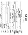
- the video CPU module 26 and video random access memory RAM 28 form a board pair for providing intelligent color graphics; featuring an on board Intel 8088 TM microprocessor, a program memory, video refresh memory, and color and zone memories.
- each video station 108 (see FIGURE 1) generates an RS172 type video signal with 312 displayed non-interlaced lines 112 with 480 picture elements (pixels 113) per line.
- the line rate is 19.9 kilohertz.
- the picture comprises four memory planes 114 each comprising 480 x 312 bits of information.
- the 480 pixels per line are divided into fifteen zones (such as zone 115 shown in phantom), each zone representing 32 pixels of a line.
- Each zone also represents 32 lines, so that the area of each zone (except the bottom most zones) represent 32 x 32 pixels, or 1024 pixels.
- 10 x 15 or 150 zones which comprise the screen area shown in FIGURE 7.
- the actual color determined for each displayed pixel is determined by a double decoding process as best seen in FIGURE 6.
- the 150 zones are represented by a zone map 117 where each zone has two bits of information.
- the zone map is divided into two planes 118 and 119 where each zone has a single bit in each plane.
- the output from the zone map is decoded by a two to four decoder 120 since two bits can represent four combinations.
- four bit planes 114 are utilized for each pixel. That is, each pixel has one bit of information in each bit plane or four bits of information total.
- These four bits of information are decoded by a four to sixteen decoder 122 with their selection of the sixteen permissible outputs are transferred to the color palettes 124, 125, 126 and 127.
- Each color palette has sixteen selectable 9-bit words or entries 129, with each 9-bit entry representing one of 512 possible physical colors.
- the zone map determines which of the four color palettes is to be selected for each zone, and the bit plane decoder 122 determines which of the sixteen words in that palette is to be used for generating the desired color for each pixel therein.
- the output from the color palettes is transferred to a digital-to-analog converter (DAC) 128 for determining the selection and intensity for each of the red, blue and green colors generated by the monitor.
- the outputs from the digital-to-analog converters 128 are transferred to the monitor 62 by 75 ohm coaxial cables.
- the three color signals and the synchronization signal are shown in FIGURE 1 as transferred to the monitor over composite bus 77.
- the video CPU 26 also includes logic for high speed graphic processing capability including the use of shifters and bit bangers as explained more fully in a later section entitled "Video CPU module".
- the shifters allow fast shifting of areas or patterns horizontally or vertically on screen 72, and the bangers enable superposition of one or more patterns over another pattern at higher speed than that possible through sole use of a central processing unit.
- the video CPU module 26 and video RAM module28 support a serial interface link through port 66 to monitor 62 over bus 73 for the receipt of keystroke information from keyboard 68 and for future use with a joy stick or "mouse" (see Bell Laboratories Patent No. 3,541,541 entitled "X-Y Position Indicator For a Display System".
- digitized touch coordinates from the monitor and touch screen 70 are multiplexed on the same bus.
- a POWER ON key switch 100 is located on the man-machine interface housing 31 as best seen in FIGURE 3. It has three positions; namely POWER OFF, POWER ON, and a MOMENTARY SYSTEM RESET.
- a four position diagnostic switch 132 (shown in phantom) is mounted within housing 31 with its positions being NORMAL SYSTEM OPERATION, REPEAT CONFIDENCE TEST, SYSTEM DIAGNOSTICS, and SERVICE CENTER DIAGNOSTICS.
- the POWER ON switch 100 and the front door 133 to housing 31 are keyed as hotel "master slaves" so that access to DIAGNOSTIC SWITCH 132 requires that both keys be in the ON position.
- four additional indicators 134, 135, 136, and 137 respectfully indicate, when ON, that all DC voltages are within specification, that the system is running properly, that an error has been detected, and that the unit is in a diagnostic mode.
- each module has four indicators 49, 49', 50, and 51' which indicate the following:
- the man-machine interface can interface through CPU module 22 via port 46 to a network communication bus 44 which in turn connects to programmable controllers 48 and other digital devices 50 such as computers, printers and the like.
- the man-machine interface may with respect to such a communication system such as the MODBUS TM network communication system, act as a primary station for a host protocol or act as a slave station for a slave protocol.
- the man-machine interface responds to requests from other units on the bus 44.
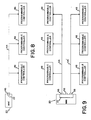
- FIGURE 8 illustrates a topology where the man-machine interface functions as a master to a family of one or more multi-drop PC's interconnected to bus 44.
- FIGURE 9 illustrates the topology where the man-machine interface utilizes ports 46 and 52 to act as hosts to two network communication buses 44 and 44', each bus interconnected to a plurality of programmable controllers 48.
- the remaining port 56 on the CPU module 22 could be used to attach to a printer such as shown in FIGURE 1.
- FIGURE 10 illustrates a topology in which the man-machine interface 20 is a host relative to programmable controllers 48 interconnected through the communication bus 44, but appears as a slave to CPU 54'.
- the man-machine interface 20 is the master as to PC's 44 but in turn is the slave to the corresponding CPU.
- the host computer may determine that an alternate data value is resident within the programmable controllers by asynchronously performing reads and writes with respect to the man-machine interface data base.
- man-machine interface as interconnected with the data communication bus 44.
- man-machine interface can, through a local area network interface module 36, be utilized with a high speed local area'network using common bus 84, including such networks using token pass systems such as those described in pending U.S. Patent Application Serial No. 241,688, entitled “Multi-Station Token Pass Communication System", and assigned to the present assignee.
- each video station 108 comprises a video CPU module 26, a video random access memory module 28, a monitor 62 and an optional keyboard 68.
- the video station is the main vehicle for operator interaction with the man-machine interface 20.
- Each video station provides a 15-1/2 inch (39.37 cm) by 11-1/2 inch (29.21 cm) flicker free medium resolution color CRT monitor (such as a Hitachi Corporation Model 8M1719 monitor) with a resolution of 480 pixels in the horizontal direction by 311 non-interlaced lines in the vertical direction, the screen being able to support 512 possible color combinations generated by the video CPU 26.
- the usable screen area is approximately 15-3/8 inches ( 39.03 cm) in the horizontal direction by 10 inches (25.4 cm) in the vertical direction.
- the linear pixel density (pixels, inch) is the same in the horizontal and vertical directions resulting in a square pixel that enables normal (round) circles to be drawn on the screen.
- the screen 72 is covered by a transparent touch sensitive panel 70 (such as an EloGraphics Inc., Oak Ridge, Tennessee model E270-19 or Sierra Con-Intrex Products, Chatsworth, California, model TBD) that senses the operator's finger position.
- the touch-station electronics within the monitor 62 digitize this to an accuracy of .1 inch ( 2.5 mm) at the screen center.
- Each touch station can be furnished with an optional detachable keyboard 68 (such as a Microswitch, Division of Honeywell Corp., Freeport, Illinois, catalog list K57282-98SC24) that includes specialized function keys for supporting graphic applications.
- a separate numerical key pad is provided together with cursor control keys.
- the keyboard can accommodate a future joy stick as an option.
- the joy stick may be plugged directly into the graphics processor 106 with the possible addition of a "mouse" (see Bell Laboratories U.S. Patent No. 3,541,541) interfacing to the graphics processor through a separate interface board.
- each video station has an auxiliary red, green, blue and sync port 63 which can be used to drive a slave station monitor 62'.
- the primary function of the slave station is to display the same image that is carried on the primary video station monitor.
- a post output contact 95 can be provided to start a hard copy device such as plotter 59 communicating with the video station through RAM module 28.
- a beeper 61 is provided with the monitor for variable pitch annunciation.
- a volume control 97 is mounted on the rear of the station while an isolated output 99 is provided for customer connection to his or her own audio amplifier system.
- a programmable contact output 65 is provided for switching up to 250 VAC at 1 ampere so as to function as a programmable alarm output relay.
- a lamp 101 is provided for POWER ON indication and a second lamp 103 is provided for an ON LINE indication.
- a degauss BUTTON 105 is also provided for degaussing the screen.
- the hardware shown in FIGURE 1 runs under control of the multi-tasking real-time disk operating system.
- the operating system provides a run time environment for the tasks that comprise the display language graphic software.
- the display language graphic software supports the features previously set forth in Table 3.
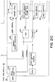
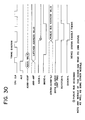
- the host software executed by the CPU module 22 interfaces with designers, configurers and operators via a set of standard menus that are accessed by a hierchical structure as set forth in FIGURE 11.
- Each of the menus includes a HELP BUTTON which, when touched, presents to the user a HELP MENU dedicated to the particular menu previously presented.
- the HELP MENU describes how to use the particular menu previously shown and it contains a CONTINUE BUTTON that, when touched, causes the particular previous menu to reappear.
- the user places the diagnostic key switch 132 (see FIGURE 3) in position 1 (normal operation) and turns on the POWER ON key switch 100.
- the man-machine interface startup sequence performs the steps set forth in Table 6.
- the mode for the selection of a mode enables designers and configurers to select designer or configurator modes respectively which are not visible to operators. This selection mode process also enables programmers to directly address the MMI operating system.
- the graphics software moves a particular control/display unit to the selection mode from its current mode when one of the following events occurs:
- the mode selection menu presents the following BUTTONS on the screen for user interaction; namely, "Help”, “Design”, “Configure”, “Operate”, and “Executive”.
- Touching the design button moves the particular control/ display unit from the mode selection mode to the designer mode and causes the object selection menu (described later) to be presented.
- Touching the OPERATOR BUTTON moves the particular control/ display unit from the mode selection mode to the operator mode, causing the graphic software to begin running the initial user application display task previously defined by the CONFIGURER. Normally, this running causes the user application's main menu to appear on the control/display unit's screen.
- the designer mode enables designers to design custom templates.
- a designer may create subpictures to form displays.
- Subpictures are components of displays and are comprised of graphic and non-graphic display language commands.
- Subpictures can be composed of other subpictures, allowing the user to create and manipulate displays of any complexity.
- Display language commands are generated by the user in an interactive environment using a touch screen and soft keys.
- Subpictures and displays may be grouped functionally, hierarchically, or logically.
- Subpictures may be edited in an interactive manner using single stepping, deletion, and insertion.
- user aids such as graticules, gravity points and automatic redrawing, provide a comfortable environment for creating displays at all levels of complexity.
- the designer editor program allows a user to create and edit a set of files containing graphic language commands. This is achieved in an interactive environment using a color graphics terminal 62 equipped with a touch panel 70 (see FIGURE 1).
- each graphic command is created, its visual effect (if any) is echoed on the screen.
- the user may step forward and backwards through the file, inserting and . deleting commands as required.
- the screen shows the graphic representation of the commands up to the current file position. The user may, however, choose to see . the entire graphic file rather than just up to the current file position.
- a secondary function of the designer editor program is to create and edit character and color libraries. These are stored as separate files and may be selected in preference to the default characters and colors which are provided.
- buttons 121 see FIGURE 7
- keyboard 68 see FIGURE 1
- the soft buttons are colored areas on the screen, each labelled with a helpful text string, which executes a given function when pressed.
- buttons are quite large, so they are grouped into "menus" - one menu on the screen at any one time. This increases the amount of screen available for drawing and is more pleasing for the user since he/she has fewer buttons to choose from at each stage.
- the MMI is able to replace one menu with another in less than 200 milliseconds, so the user does not notice an appreciable delay.
- Some menus use the entire screen area in order to provide large, easy to use, soft buttons. This causes the screen contents to be temporarily lost, but redraw time is predicted to be less than one second, so the user is not held back while the display is regenerated.
- the user has the option of displaying part of the command file in textual form. This involves the use of a scrolling buffer area 152 on the screen and shows several commands in near-English form.
- the buffer scrolls up and down such that the current command is at the center of the buffer. Previous commands are shown above and later commands (if any) are shown below.
- the current command may have several arguments, such as an X coordinate, Y coordinate, etc. One of these is marked to signify that it is the "Current Argument". This is the first argument by default, but the user can step through the arguments as desired.
- the user has the ability to position the Text Window anywhere on the screen. He/She may choose to move it to an unused portion of the screen if it is interfering with the current drawing. By default, it is shown at the lower left corner of the screen.
- the designer editor program structure consists the following four basic units:
- the display commands are stored in temporary buffers and are written to permanent files at the conclusion of the editing session. These files may later be read back into the temporary buffers for further processing.
- the interpreter is used to draw the command file and is invoked by the Designer Editor as each edit is made. Reference is made to the appropriate character and color libraries.
- a subpicture is a collection of display language commands that perform a logical function. This function may be graphical or non-graphical in nature.
- a subpicture may contain the display language commands to draw a motor start button on the screen, displaying the state of the motor by the button color.
- it may contain the display language commands to perform the calculations that determine the average downtime for all motors.
- a subpicture is a display file entity and can contain any of the graphical commands described later.
- subpictures can support the following additional capability:
- the non-graphical display language commands include expression calculations and control flow. Subpictures are stored as filed in directories.
- a display is a collection of one or more subpictures that make up a cohesive, unifying action. This action may be graphical or nongraphical in nature. Displays are interpreted as tasks that may be created, aborted or scheduled. Displays are made up of subpictures copied from libraries and various directories. Subpictures for a given display may come from a single directory, thereby facilitating the organization of displays in any desirable manner. Displays are different from subpictures in that they also contain information of their composition, their scheduling, and their links with other displays. This extra information is determined through the configuration process.
- Displays are stored as files in directories.
- the MMI has the capability to support a variety of invisible displays.
- Invisible displays may run automatically once initiated but are capable of being started and stopped by the operator, scheduled at different rates, and used for a broad range of activities, such as history processing (e.g., data compression for trends and other data), derived point calculations (some derived point calculations can be part of the data acquisition phase), and customized alarm monitoring.
- history processing e.g., data compression for trends and other data
- derived point calculations e.g., data compression for trends and other data
- derived point calculations e.g., derived point calculations can be part of the data acquisition phase
- customized alarm monitoring e.g., derived point calculations, and customized alarm monitoring.
- Up to eight invisible displays can run concurrently. There is no limit to the number of different invisible displays that can be scheduled.
- Task scheduling may be changed dynamically, either by explicit control from the designer or by internal determination. Tasks may be spawned or destroyed dynamically, either through direct intervention of the designer or under control of a supervisory task that acknowledges their completion or startup.
- Each domain may be individually opened and concurrently written to by a display task that is being interpreted.
- the MMI contains a hierarchical directory and file system in which the leaves are files and the nodes are directories.
- a directory is simply a list of files.
- the MMI directories typically list files consisting of subpictures, displays, templates and application specific data.
- the MMI also supports the notion of libraries. Libraries can be considered special directories in that they contain no other directories, they contain only standard templates, color definitions, text font definitions and symbol font definitions; and in the case of standard templates, standard color libraries and standard character libraries, they are read only.
- transactions consisting of subpicture and display creation, deletion, and modification emanate from a single directory. This eliminates naming problems as well as problems due to multiple copies of the same (or slightly modified) file.
- the MMI graphics software moves a particular control/display unit to the designer mode from the mode selection mode when the mode selection menu appears on the unit's screen and the design button is touches.
- the designer mode provides the following menus to support design of custom templates:
- the object selection menu enables a designer either to address complete directories via the directory options menu or to address individual templates, displays and subpictures in a particular directory via the subpicture design options menu.
- the directory options menu enables a designer to select a disk volume, to select, create and delete individual directories and to list the names of all directories.
- the subpicture design options menu enables a designer to create, delete and copy templates, displays and sub p ictures within a particular directory, to list the names of the templates, displays and subpictures within a particular directory and to request design of a specific template, display or subpicture within a particular directory.
- the graphics software begins running a designer editor program, that enables the designer to build and modify a specific template, display, or subpicture.
- the designer editor program When the designer editor program begins running, it presents the designer editor main menu to the user.
- the designer editor main menu enables the designer to select or access menus that select one of a group of designer editor secondary menus, (described below), each one of which enables the designer to return to the designer editor main menu.
- Each designer editor secondary menu is dedicated to a particular type of function (e.g., generate move or draw command, define plot or trend, etc.) supported by or accessed via the designer editor program.
- the editor also presents a group of function buttons in a small, user selectable area of the screen. The remainder of the screen is used to depict the image produced by interpreting the current contents of the template, display or subpicture being designed. Touching one of the function buttons causes the designer editor to perform a single function, for example, the addition of a particular display language command to the template, display or subpicture.
- the special function menus are each used to obtain a specific item of information from a designer.
- a special function menu is requested via either the designer editor main menu and/or a designer editor secondary menu whenever the item of information obtained through the special function menu is required by an option selected on the requesting menu.
- the object selection menu is used in both the designer mode and the configurator mode, and is depicted in FIGURE 11.
- the object selection menu presents the following buttons to the user: directories, subpictures, help, and select mode.
- Touching the subpicture button causes one of the following two events to occur:
- Touching the select mode button moves the particular touch station from the designer mode to the mode selection mode, causing the mode selection menu to appear on the screen.
- the directory options menu is used in both the designer mode and the configurator mode, as shown in FIGURE 11.
- the directory options menu presents the following buttons:
- the directory options menu only supports access to directories that have been created using the create directory button. Directories created directly by users via the operating system utilities cannot be accessed via the directory option menu.
- Touching the select volume button enables a designer or configurer to enter, via the keyboard, the name of the current disk volume to which all directory references are to apply.
- Touching the select directory button enables a designer or configurer to enter, via the keyboard, the name of the current directory in which all files are to be stored and retrieved.
- Touching the list directories button causes the names of all directories stored on the floppy disk drives to be listed on the screen.
- Touching the create directory button enables a designer or configurer to enter, via the keyboard, the name of a new directory that is immediately created.
- Touching the delete directory button enables a designer or configurer to enter, via the keyboard, the name of a directory that is immediately deleted.
- Touching the select mode button moves the particular control/ display unit from the designer mode to the mode selection mode, causing the mode selection menu to appear on the unit's screen.
- Touching the select object button causes the object selection menu to be presented.
- the subpicture design options menu presents the following buttons:
- Touching the create subpicture button enables a designer to enter, via the keyboard, the name of a new subpicture that is immediately created.
- Touching the delete subpicture button enables a designer to enter, via the keyboard, the name of a subpicture that is immediately deleted.
- Touching the copy subpicture button enables a designer to enter, via the keyboard, the name of an existing subpicture and its respective directory and the name of a new subpicture in the current directory to which the existing subpicture is immediately copied.
- Touching the list subpictures button causes the names of all displays, subpictures and templates in the current directory to be listed on the screen.
- Touching the edit subpicture button enables a designer to enter, via the keyboard, the name of a file of display language commands which is to be edited. As soon as the subpicture name is entered, the following events occur:
- Touching the select mode button moves the particular control/ display unit from the designer mode to the mode selection mode, causing the mode selection menu to appear on the unit's screen.
- the designer editor is a program that enables a designer to build and modify a file of display language commands, (i.e., a template, display or subpicture), one command at a time.
- a file of display language commands i.e., a template, display or subpicture
- the designer editor program resembles a line oriented text editor in that it maintains a pointer to a current location in the file being designed.
- a designer directs the designer editor to perform a single function, for example, addition of a particular display language command to the file being designed at the current file location, by touching a function button on one of the designer editor secondary menus.
- the screen contents include:
- the utility menu presents a relocate menu button, that when touched, enables the designer to relocate the menu to another screen location by touching the new screen location.
- the designer editor main menu presents the following buttons that are used to select the designer editor's secondary menus:
- Touching the control function button causes the control functions menu to be presented.
- Touching the edit functions button causes the edit functions menu to be presented.
- Touching the move and draw button causes the move and draw menu to be presented.
- Touching the character functions button causes the character functions menu to be presented.
- Touching the plots and trends button causes the plots and trends menu to be presented.
- Touching the utility button causes the utility menu to be presented.
- Touching the color functions button causes the color functions menu to be presented.
- Touching the subpictures button causes the subpictures menu to be presented.
- Touching the variables button causes the variables menu to be presented.
- Touching the calculation button causes the keyboard menu to be presented.
- a display language command is added to the display file being edited, at the current file location, that when interpreted in operator mode, causes the value of the named parameter to be set equal to the current value of the entered expression.
- the expression has no data types associated with parameters, but instead the data itself carries a type identifier.
- the interpreter accepts and operates on any data type. No type checking is performed or necessary. This greatly facilitates program development and execution.
- Touching the database functions button causes the database functions menu to be presented. Touching the I/O functions button causes the I/O function menus to be displayed. Touching the end button causes the display file being designed to be stored to disk and causes the subpicture design options menu to reappear. Touching the print button causes the contents of the file currently being designed to be printed on the default graphic hard copy device defined in the logic-to-physical unit mapping display.
- the character library editor and the color library editor are separate programs having their own menus that can be invoked from the character functions menu and the color functions menu respectively.
- Real expressions may contain the operators +, -, * , /, and (exponentiation).
- Arithmetic constants may be expressed in decimal format, integer format or scientific (E) notation.
- Real expressions may contain the arithmetic functions abs (x) , sqr (x) , sin (x) , cos(x), exp (x) , ln (x) , sqrt(x), and arctan(x); where x is a real expression.
- Boolean expressions may contain the Pascal predicate odd (x).
- Boolean expressions may contain the predicate eof, which returns the value true when the channel currently open is at the end of a file and false when the channel currently open is not at the end of a file.
- Expressions may contain any level of parentheses, e.g., a*(b* (c+d)).
- the function "connected”, when applied to a database variable, returns the value True when the variable is configured for update/download from/to a PC by the data acquisition package and otherwise returns the value False.
- the function valid when applied to a database variable, returns the value True when a display has previously validated the variable's value and otherwise returns the value False.
- the function enabled when applied to a database variable, returns the value True when the value of the variable may be modified by an active display and the database package otherwise returns the value False.
- a function also exists to convert an array of PC registers into a text string and vice versa. This can impact DAP and database as well. Functions also exist to test or set a bit in a PC register in the database.
- the currently selected foreground color and the currently selected background color is displayed on all of the designer editor's menus.
- the current cursor position is visibly identified and blinking.
- the control functions menu presents the following buttons:
- Touch buttons may be designed into a screen picture via the "Define Button” function button. These touch buttons may be designed to call another picture or portion of a picture, change a data base boolean, jog an analog variable, with hold-down for continuous slew and auto repeat, initiate the "change an analog or logical” procedure, and initiate any calculation, display, procedure or computer “process” that has been designed in designer mode.
- Some touch buttons that are usually designed into the visible displays include tag callup, alarm acknowledge, last display, and help.
- the function buttons presented solely by the control functions menu perform the functions and/or generate the display language commands as set forth in Table 7.
- the edit functions MENU presents the following function BUTTONS:
- the move and draw menu presents the following function buttons:
- buttons presented solely by the move and draw menu perform the functions and/or generate the display language commands set forth in Table 9.
- a standard text library is provided that defines the fonts for a standard ASCII set (95 upper and lower case characters) in a 6 x 8 cell.
- Two standard sizes of characters are provided; namely, 6 x 8 and 6 x 6 dot matrices (with a 48 character set).
- buttons presented solely by the character functions menu perform the functions and/or generate the display language commands as set forth in Table 11.
- the character functions menu presents read commands to enable real, integer, boolean and character string data to be read from disk files.
- Real data may be read in either scientific or integer notation.
- chart_height chart height in screen units (pixels)
- This conversion operator is normally used on the height argument of a bar or point but may be used in arguments to other commands as well; thereby permitting more sophisticated scaled drawings.
- This function may be used in a numeric expression in display language. It yields the following real value: (upper - Lower) / number of intervals
- the purpose of this function is to permit placing things like tick marks and labels on the screen at places which are significant in terms of engineering units.
- a trend is a graphical representation of data corresponding to that written with a pen on paper as the paper moves.
- a trend may be in one of two formats: either a bar or a point chart. Bar charts are by far the most readable. Each unique item trended can be linked to a different color.
- a chart may have a threshold value associated with each data point. Whenever that threshold value is exceeded, another color specified by the designer is utilized. Trends may move in any perpendicular direction (e.g., up, down, left, right) but typically move from right to left.
- Each point chart may have at most six scales, three on each side. These scales may be represented in floating point. Each point chart may trend the values of between one and six variables.
- Bar charts can have a maximum of 2 data points plotted per chart. Bar charts may have a color linked to a value, so that the color of a bar varies with its height. A third color is also mapped for any overlap regions.
- buttons presented solely by the plots and trends menu and used to operate display language commands are described in Table 12.
- the utility menu presents the following function buttons:
- buttons presented solely by the utility menu perform the functions and/or generate the display language commands as set forth in Table 13.
- the color functions menu presents the following function buttons:
- the colors are organized into four color palettes 124, 125, 126 and 127 containing 16 colors (entries 129) each.
- the screen is divided into a 15 x 10 grid, each grid called a "zone" (e.g., zone 115).
- the color palettes are mapped to the grid, thus determining which color palette is used at a given screen position.
- a common use for this feature is to map the user's area of the screen to one color palette and the system's area of the screen to another color palette.
- the individual color palette entries are read by the hardware that controls the gun intensities.
- Any symbol in any display can be made dynamic. If it is a discrete symbol (on/off) it can change color or shape with change in state; it also can change its position (in X and/or Y coordinates) and any of its dimensions. Examples include pumps, motors, valves, and pipes (lines). Similarly, analog signals can be used to change symbols. Examples include bar graphs, reservoir levels in tanks, etc.
- buttons presented solely by the color functions menu perform the functions and/or generate the display language commands as set forth in Table 14.
- the subpictures menu presents the following function buttons:
- Table 15 describes the buttons presented by the subpictures menu along with the functions and/or the display language commands generated.
- the variables menu presents the following function buttons:
- parameters that are created in a calling subpicture, or in global variables and local variables may be used as scalars or arrays of the type boolean, real or character string.
- the length of a character string is defined by its use.
- buttons presented by the variables menu perform the functions and/or generate the display language commands set forth in Table 16.
- the database functions menu presents the following function buttons:
- buttons presented by the database functions menu perform the functions and/or generate the display language commands set forth in Table 17.
- the I/O Functions Menu presents the following buttons:
- buttons presented by the I/O functions menu perform the functions and/or generate the display language commands as set forth in Table 18.
- logical unit numbers and physical devices The relationship between logical unit numbers and physical devices is fixed; that is, a particular logical unit number always refers to a specific physical device.
- Operator capability to reroute an I/O stream from one I/O device to another I/O device can be implemented via a display that: (1) opens a stream to each of the potential I/O devices; (2) selects the stream to which all read and write commands currently apply via a select stream command having a parameterized logical unit number; and (3) enables the operator to modify the value of the parameterized logical unit number.
- the character library editor is a program that enables a designer to create, select, delete, and modify character libraries.
- the character library editor program is invoked by touching the edit character library button on the character functions menu, as described earlier.
- buttons presented by the character library editor menu perform the functions set forth in Table 19.
- the color library editor is a program that enables a designer to create, select, delete and modify color libraries.
- the color library editor program is invoked by touching the edit color library button on the color functions menu, as ddescribed earlier.
- the color library editor menu presents the following function buttons:
- buttons presented by the color library editor menu perform the functions set forth in Table 20.
- the menus described in this subsection are used to get a specific item of information from the user. When this is achieved, the secondary (main) menu which invoked the function menu is resumed.
- Each function menu is also equipped with a "Quit" button which, when touched, aborts the current command action and immediately returns the program to the calling menu.
- Each zone button is set to the current palette number when pressed.
- Each zone button increments its palette assignment by 1 each time it is pressed (module 3).
- the configurator mode enables configurers to configure templates.
- the man-machine interface graphics software moves a particular control/ display unit to the configurator mode from the mode selection mode when the mode selection menu appears on the unit's screen and the configure button is touched.
- the man-machine interface configurator mode provides the following menus to support configuration of templates:
- the object selection menu enables a configurer to address complete directories via the directory options menu or to address individual templates, displays and subpictures in a particular directory via the configurator mode main menu.
- the directory options menu enables a configurer to select, create and delete individual directories and to list the names of all directories.
- the configurator mode main menu enables a configurer to delete and copy templates, displays and subpictures within a particular directory, to list the names of templates, displays and subpictures within a particular directory, and to request editing of the plant data base.
- the graphics software supports the request via the configurator editor program, described above.
- the configurator menu is presented.
- the database editor menu is presented.
- Two of the designer editor function menus described above, the digitizer menu and the keyboard menu, are also accessed via the configurator menu whenever an item of information obtained through the digitizer or keyboard menu is required by an option selected on the configurator or database editor menu.
- a template is configured is highly dependent on how it was designed. For example, if a template has within it a subpicture of a control loop, there are various ways this part of the template could be configured depending on how it was designed. Examples of two extreme cases are as follows:
- the above examples suggest that a template may be arbitrarily complicated or easy to configure depending on how cleverly it is designed. Therefore, to insure consistency within configurator mode, guidelines for designing templates have been established.
- Parameters have no types:
- the data value for a parameter may be any of the following types: irectory name, display name, real number constant, integer constant, logical value constant, plant data base mnemonic (or part of one; as above), string constant, color, or palette name.
- Type conversion is performed automatically by the interpreter when possible. This facilitates configuration since the user need not concern himself/herself with the data types for the variable.
- a typical template may have many subpictures, each requiring parameters similar to the example above.
- the configurator menu aids the configurer in naming these parameters by "walking" him/her through the template, subpicture by subpicture, parameter by parameter, asking for a value or mnemonic for each parameter. Again, the order in which the walk through occurs depends on how the template was designed.
- the configurator mode main menu presents the following buttons:
- Touching the delete subpicture button enables a configurer to enter, via the keyboard, the name of a subpicture that is immediately deleted after confirmation.
- Touching the copy subpicture button enables a configurer to enter, via the keyboard, the name of an existing subpicture and the name of a new subpicture to which the existing subpicture is immediately copied.
- Touching the list subpicture button causes the names of all displays, subpictures and templates in the current directory to be listed on the screen.
- Touching the configure subpicture button enables a configurer to enter, via the keyboard, the name of a file containing display language commands which are to be configured or re-configured. As soon as the file name is entered, the configurator menu is presented, enabling the configurer to configure or re-configure the entered file.
- Touching the edit plant data base button causes the database editor menu to be presented, enabling the configurer to define or maintain the plant data base.
- Touching the configure communications system button causes the configure communications system menu to be presented, enabling the configurer to change the default values of the communication interface parameters (e.g., baud rate, parity, stop bit) so as to match programmable controller (PC) parameters.
- the communication interface parameters e.g., baud rate, parity, stop bit
- Touching the select mode button moves the particular touch station from the configurator mode to the mode selection mode, causing the mode selection menu to be presented.
- Touching the select object button causes the object selection menu to be presented.
- the configurator editor is a program that performs five functions:
- Functions 1, 2, and 4 are supported via the configurator menu.
- Function 3 is supported via the database editor menu.
- the configurator editor program is compatible with both the procedure oriented design method and the object oriented design method supported by the designer editor program.
- FIGURE 11B illustrates the structure chart of the configurator editor.
- the configurator menu presents the following buttons:
- the configurator menu is presented with a graphic representation of the current display file and an optional text window in the same manner as a secondary designer editor menu is presented.
- buttons presented by the configurator menu function are set forth in Table 21.
- the database editor menu presents the following buttons:
- buttons presented by the database editor menu function are set forth in Table 22.
- the Edit Coil/Register menu presents the following buttons:
- buttons presented by the Edit Coil/Register menu function are set forth in Table 23.
- a port selection menu is first presented. After a port is selected, the configurer port menu is presented. This menu is used to configure all serial ports in the system and to assign ports to communications systems functions.
- the initial man-machine interface has three serial ports associated with the CPU module for interfacing with user equipment. The user configures each port's hardware characteristics and he assigns communications system functions to some of the ports.
- One or two ports of the three may be communications system master ports on which up to 32 PC's can be connected. Any of the ports (up to two initially) may be assigned to printers. Any one port may be assigned as a communications system slave. This port then accepts communications system commands from a host computer.
- the configure communications system menu presents the following buttons:
- buttons presented by the configure communications system are set forth in Table 24.
- the operator mode enables operators to control and/or monitor an industrial plant by viewing images and touching buttons depicted on the screen by visible displays.
- the graphics software moves a particular video station to the operator mode under the following circumstances:
- the initial user application display task specified by the configurer via the configurator menu begins running for the station at an intermediate priority.
- the operating system's executive level menu is presented and the operator mode is exited.
- the initial user application display task and any other display tasks that run in the operator mode are user configured. Therefore, both the visible displays and invisible displays being interpreted at any given time for a particular video station that is in the operator mode are user selectable by one of the following two methods:
- a display file that has been configured as operator mode disk resident is only brought into memory when a spawn or chain command is executed that require the file be memory resident.
- Programmable controllers of the present assignee can be connected on a common bus which has a low to medium speed centralized data communications system.
- this centralized system there is a single dedicated host computer and up to 32 remote programmable controllers.
- the system is capable of communications over a distance of 15,000 feet with limited distance modems or any distance over phone lines with modems.
- the acquisition and dissemination of data is done as follows:
- the plant data base is the mechanism by which displays are linked with the user application.
- a typical application can be controlled via programmable controllers (PC's).
- PC's programmable controllers
- Each PC contains a number of internal variables which can be read from or written to graphic displays. These PC internal variables come in two varieties; namely, coils and registers. Each coil or register is assigned a reference number. PC's are also assigned reference numbers so that in a multi-PC application, each PC coil or register can be uniquely specified with a programmable controller number and a register/coil number.
- the mechanism by which programmable controllers communicate with each other and with graphics is via the communications system.
- the plant data base contains a reflection of the application's coils and registers. Displays read and write to the plant data base as though they were directly conversing with programmable controllers. The plant data base is continuously maintained to reflect the current state of the PC variables via the data acquisition package which communicates to the PC's.
- the data acquisition package performs the following functions asynchronously with respect to the remainder of the graphics software:
- the data acquisition package When the data acquisition package is communicating with devices on the network, it attempts to maximize throughput. In severe cases where the data is totally scattered throughout the network, the data acquisition package may not attempt any data transfers and may abort operations.
- the data acquisition package automatically modifies and re-optimizes its operation each time a configurer installs a display that in any way redefines the plant data base.
- DAP data acquisition package
- the plant data base contains two datatypes, called coil and register, to reflect the naming convention used in programmable controllers. Coils are boolean (true/false) variables whereas registers are real variables. While internally to the PC's registers are integer values, the capability is provided for automatic conversion to engineering units on input (and conversion back on output) so that the displays need only deal with real values.
- Each database element has a user assigned name by which it can be referred.
- the name is hierarchical in nature. This means that logically related database items can be grouped together in convenient ways. This capability is especially useful when configuring templates, since many data base elements can be referred to with a single reference. '
- Autolog Facility An attribute of every database element is the Autolog Facility. This feature allows all operator changes to the database to be automatically logged. This facility can be switched on or off from displays.
- every datapoint can be assigned a protection level. Lockout from modification to the datapoint is automatic if the security level of the operator is not sufficient. Six levels of protection are provided.
- Elements in the database may be designated as being "connected" to a register or coil in a particular PC. Although displays use the database as though they are directly communicating with PC's, the data acquisition package actually does the communication.
- Each database element may be assigned a scan rate so that it may reflect the actual changes occurring in a PC within a certain time interval. Also, when a connected database element is modified from a display, the new value is written out to the PC by the data acquisition package. Consideration is given to the concept of polling PC's only for (1) variables presently on the screen, (2) alarmed variables, and (3) other specifically requested variables.
- DBM database management
- a database is assigned to a display at configuration time and the ability exists to copy one database to another so that the only remaining task for the configurer is to change the PC routing.
- the user need not specify the database prefix thereafter. However, the user can explicitly request or connect an item in another database by referring to the full name.
- Two databases are provided as defaults at system configuration, one for system data and one for process variables. These are named /SYS/ and /DBO/. If no database is specified, /DBO/ is the default database.
- Two default database handles are provided to correspond to the two default databases. These are internal variables not available to the user but available to application programs through cosmic memory. Within this specification the names pDBO and pSYS are used for these handles.
- the database called /SYS/ is for system data and contains the following default elements:
- the user may add system variables if desired.
- the password for each touch-station serviced by an Industrial Graphics Processor (IGP) is stored in the IGP's /SYS/database and is accessible via a reserved identifier.
- IGP Industrial Graphics Processor
- a display might have a subpicture which contains the following variables:
- the subpicture was designed to have one parameter named X.
- process variables exist for each of the display variables, but the names are cumbersome:
- the user can resolve all references by passing PLANT22. AREA18. GROUP2. STEAMTANK. PRESSURELOOP for the parameter X.
- the MMI can search for subnames in the database.
- the result of this type of request is called a database handle.
- This handle tells the database manager where to start searching for a name (It can be thought of as a variable which holds a prefix).
- a dbHandle can be thought of as a pointer to one of the modes.
- the above example can be visualized as follows:
- a database descriptor is a record which describes a datapoint both in form and where it comes from (internally or from a programmable controller).
- Each field within a descriptor is modifiable through a DBM function while it is specific to that field.
- the register data type is a real number.
- an automatic conversion takes place between PC register units and engineering units.
- the fields Span and Zero are provided.
- the field Eng Units is provided to save six character string to describe the engineering units used.
- the fields maximum limit and minimum limit are provided to limit the maximum and minimum values that an operator may assign to the engineering unit's value.
- the coil datatype is a boolean value (true/false).
- the operating system's Executive Level Display allows user access to all of the executive level commands. These executive commands include the following:
- Diagnostics typically provide powerful tools to assist during the manufacture, field analysis, and repair of computer based systems. Two additional levels of diagnostics are required. The first requirement is that on a power up reset, each processor executes a self test to insure the integrity of its respective board prior to each board going on line. The second requirement is to have continuous testing of the hardware while the system is on line and running, to insure the integrity of the operational system and to permit shutdown of a malfunctioning system. This second level of diagnostic support is under direct control of the system operating system (OS).
- OS system operating system
- run time validity checks In addition to the run time diagnostics which look specifically for hardware faults in a running system, the operational software performs validity checks on its own internal operations. Although these run time validity checks are not technically a diagnostic, they can be useful in detecting hardware failures, even though the actual failure may not be isolated. For example, in a debugged software system, stack underflow/overflow may be indicative of a CPU memory failure. There are two levels of run time validity checks:
- the purpose of a power up confidence test is to provide a self test capability on each CPU based board.
- the power up confidence test resides in on-board PROM/EPROM. Errors detected are reported externally via onboard light emitting diodes (LED's) (49, 49', 51, 51', see FIGURE 2) and internally via the bus status registers in the individual boards.
- the confidence test is a GO-NO-GO test.
- the board (module) is tested to whatever extent possible, without requiring off-board hardware. If the module uses a second module (e.g. the CPU module and memory module) to form a board set, then the confidence test executes from the hardware resident on the module with the CPU. Examples are:
- the confidence test can be executed repeatedly for maintenance purposes by setting the diagnostic switch. Some examples ot typical confidence tests are listed below:
- the confidence test is used to facilitate system repair by isolating failures to a board level but is not used to repair the boards themselves.
- the module If the module passes the confidence test, it hands off control to the operating system software located on the same on-board PROM/EPROM. If the confidence test detects an error, control is retained indefinitely by the power up diagnostic, thereby preventing the system from utilizing defective equipment. An exception is the floppy disk controller module 30 (FIGURE 1) which hands over to the operating system bootstrap on I/O failures due to drive or media failure and which can better be reported via the video station 108 through the operating system software.
- a reset is required to restart the system if an error occurs.
- a power up reset invokes the power up confidence test.
- the confidence test is designed to test all possible hardware . options. Hardware jumpers are available on each board (module) to indicate which options are present.
- run time diagnostics The purpose of run time diagnostics is to detect hardware failures in a running system.
- the run time diagnostics are under control of the operating system. All hardware that can be tested in a manner which does not interfere with the execution of the operational software is tested.
- the run time diagnostics handle failures in a manner similar to the confidence test. Any fatal error takes the module off line in whatever fashion the system software deems appropriate. After the board is off line the error is reported to the user.
- Run Time Diagnostics are:
- Run time diagnostics accomplish two objectives, as outlined below.
- Run time diagnostics provide continuous testing of system hardware in a manner which does not noticeably affect system software. It should be noted that some of the tests contained in the confidence test may not be practical in the run time diagnostics. For example, the RS-232C ports cannot be placed in loopback mode without the risk of losing input characters (unless the operating system can schedule this event).
- the confidence test is restricted to testing on-board hardware. During the execution of run time diagnostics, it may be reasonable to test some of the hardware off-board, such as a limited portion of global memory and interface.
- run time diagnostics are more comprehensive than the power up confidence test.
- the man-machine interface can be configured in the field to have a variety of options: from 1 to 2 touch or réelle stations and multiple serial outputs and from 1 to 4 floppy disks to Winchester hard disks. In a normal computer system this implies a complex system generation procedure. Some configuration changes, such as the number of floppy disk drives, do not require separate disks but are detected at initial bootstrap of the system.
- the application specific portion of the system generation process occurs in configurator mode.
- the user defines the user list and associated access privileges as well as network topology.
- the image displayed at the secondary display unit may be controlled by the primary control/display unit.
- the service center mode provides for the interrogation of status information via a serisl interface port of the CPU module via ASCII commands.
- a line protocol allows for the down line loading of code which may then be executed by the onboard processor.
- the latter facility allows the loading of a more complex line driver which may in turn load more complex diagnostic software.
- the man-machine interface provides several libraries of standard templates, described in this section, that can be configured for specific user applications. Where the user desires displays different than those that can be configured from the standard templates, the graphics software enables the user to customize the standard templates and to design and configure custom templates via the designer and configurator modes.
- the general standard template library includes the following standard templates:
- the process industry standard templates library includes the following standard templates:
- the discrete parts manufacturing industry standard templates library includes the following standard template: Motor control center bucket.
- the standard point template shown in FIGURE 48 is a visible template that provides detailed information and operator selectable current value trending of a single measured (actual or derived) variable.
- the measured variable can be displayed on a 3 inch (7.62 cm) x 6-3/4 inch (17.1 cm) analog controller faceplate or on a 3 inch (7.62 cm) x 6-3/4 inch (17.1 cm) analog indicator faceplate.
- FIGURE 48 The standard point template for an analog controller faceplate with current value trending, internal adjustments, numeric keypad and group, and overview buttons selected is shown in FIGURE 48.
- the analog controller faceplate presents the following information:
- the analog indicator faceplate is identical to the analog controller faceplate except as follows:
- the standard point template provides an operator selectable current value trend graph of the measured variable.
- the trend graph 270 is enclosed in a 7 inch (17.8 cm) square.
- the trend button 271 is a standard toggle button that alternately initiates a new current value trend graph (i.e. starts a new trend graph beginning with the current value of the measured variable) and erases the previous trend graph.
- the trend period (time between trended values) has a default value in case a trend period is not specified.
- the value of the trend period is displayed digitally. Touching the period button 272 causes the standard numeric keypad template to be presented on the right of the screen and causes the period button to blink.
- a new current value trend graph is presented using the new trend period and the standard numeric keypad template is erased. Modifications of the trend period remain in effect when the trend graph is erased for purposes other than further modification of the trend period.
- the zero and full scale values 274, 275 of the trend graph default to those of the measured variable. Touching the zero scale value display location on the screen causes the numeric keypad template 277 to be presented on the right of the screen and causes the zero scale value to blink. When the new zero scale value is entered, a new current value trend graph is presented using the new zero scale value and the standard numeric keypad template is erased.
- Modifications of the trend graph's zero scale value remain in effect when the trend graph is erased for purposes other than further modification of this value.
- the trend graph's full scale value may be similarly modified.
- the date and the time are displayed in the upper right hand corner of the 7 inch square (locations 279 and 280 respectively) that encloses the trend graph.
- the internal adjustments include hi alarm limit 282, lo alarm limit 283, proportional gain 284, reset 285, derivative time 287, full scale value 275 and zero scale value 274.
- the internal adjustments may be alternatively displayed and erased by consecutively touching the parameter button 289.
- Touching the label, value or units of a particular internal adjustment while the internal adjustments are being displayed causes the standard numeric keypad template to be presented on the right of the screen and causes the label of the particular internal adjustment to blink.
- the standard point template provides an optional, configurer selectable group button and an optional, configurer selectable overview button. These buttons are presented in operator mode only when previously selected by the configurer.
- touching the group button causes a chain to a configurer specified display, normally the standard 4-loop group display associated with the standard point display being viewed.
- touching the overview button causes a chain to a configurer specified display, normally the standard 4-loop overview display associated with the standard point display being viewed.
- the standard multi-trend template, depicted in FIGURE 49 is a visible template that provides current value trending of from one to six measured (actual or derived) variables on a single set of axes.
- the trend period (time between trended values) has a default value in case a trend period is not specified.
- the value of the trend period. is displayed digitally. Touching the period button 291 replaces the grid (but not the scales) with the standard template that presents the standard numeric keypad template and a message directing the operator to enter a new value for the trend period. When the new value is entered, a new current value trend graph is presented using the new trend period. Modifications of the trend period remain in effect when a standard multi-trend display is erased for purposes other than further modification of the trend period.
- the default tags (database handles) of the variables being trended are specified during configuration. Touching a tag descriptor location on the screen replaces the screen contents with a standard template that presents the standard QWERTY keyboard template and a message directing the operator to enter a new tag. When the new tag is entered, a new current value trend graph is presented incorporating the new tag. Modifications to the trend graph's tag remain in effect when a standard multi-trend display is erased for purposes other than further modification of one of these tags.
- the engineering units ultiplier of each variable being trended is similarly configured and may be similarly modified, with the standard numeric keypad template utilized for input of the modified value (see FIGURE 48, Keypad 277).
- the default zero scale value 292, full scale value 293 and engineering units multiplier 294 of each variable being trended is specified during configuration. Touching the screen location that displays one of these values erases all data dependent on this value and replaces the grid with a standard template that presents the standard numeric keypad template and a message directing the operator to enter the desired value. When the new value is entered, all data dependent on the new value is drawn and a new current value trend graph is presented using this new data. Operator modifications made to a zero scale value, full scale value or engineering units multiplier remain in effect when the standard multi-trend display is erased for purposes other than further modification of the value.
- the date 295 is displayed in the template's upper right hand corner.
- the standard alarm definition/status template shown in FIGURE 50, is a visible template that enables configurers to define and operators to look up and acknowledge the states of all alarm points being monitored by the man-machine interface.
- the standard alarm definition/status template is designed for configuration as one or more pages of standard alarm definition/status displays.
- the standard alarm/ definition/status template presents the following information:
- the standard alarm processing template is an invisible template that, when configured and interpreted in the operator mode, processes each alarm point defined on a standard alarm definition/status template according to the logic described above.
- the state of each coil associated with an alarm point is either proper or trouble (not-proper).
- the state of each alarm point is either normal or alarm (not normal).
- the condition of each alarm point whose state is "alarm" is either unacknowledged or acknowledged and, optionally, either unsilenced or silenced.
- Alarm silencing is an optional feature that, when desired, is enabled during configuration of the standard alarm processing template.
- the alarm beeper 61 may be silenced from any standard display without the operator viewing and acknowledging the information that identifies the alarm point(s) as in the unsilenced alarm condition.
- the operator merely touches a silence button 311 on the standard display.
- the alarm beeper may be similarly silenced from any custom display that presents an appropriately designed and configured silence button. When the alarm beeper is so silenced, all alarm point(s) in unsilenced alarm condition change to the silenced alarm condition.
- no display may be used to silence the alarm beeper without operator viewing and acknowledgement of information that identifies the alarm point(s) in the alarm state.
- An alarm is acknowledged by touching the acknowledge button 309 on any standard display (standard alarm definition/ status display or standard alarm history display, see FIGURE 1) that identifies the alarm point in alarm.
- An alarm point may also be acknowledged from any custom display that presents an appropriately designed and configured acknowledge button.
- an alarm point's state When an alarm point's state is alarm, it remains alarm until the folling conditions are both met: (1) it has been operator acknowledged, i.e., its condition is acknowledged, and (2) the state of the coil associated with the alarm point is proper.
- the alarm point's state changes from normal to alarm, the alarm point's condition is initially unsilenced and unacknowledged.
- an unsilenced, unacknowledged alarm condition becomes acknowledged, it also becomes silenced.
- the standard alarm history template shown in FIGURE 51 is a visible template that provides a table listing the most recent 16 alarms to transition from normal to alarm state in reverse chronological order (most recent transition to alarm first). This alarm history template also enables an-operator to acknowledge the alarm point in alarm state.
- the standard alarm history template is designed for configuration as a one page standard display.
- the standard alarm history template presents the following information:
- the standard communications network status and transient error counts template is shown in FIGURE 52. It is a visible template that tabulates the following data on a MMI system's one or two communications network (such as communication bus 44 shown in FIGURE 1):
- the messages sent and retried are zeroed each time the operating system is booted. Each of these items is stored in a double word to eliminate the possibility of overflow.
- the standard programmable controller status template is shown in FIGURE 53. It is a visible template that tabulates the following data on from one to thirty-two programmable controllers interfaced to a MMI system via a communications bus (such as PC's 48 via bus 44 to MMI 20 shown in FIGURE 1) :
- the configurer specifies the communication network channel (bus) number and the total number of programmable controllers on the channel.
- the messages sent and retried per programmable controller are zeroed each time the operating system is booted. Each of these items is stored in a double word to eliminate the possibility of overflow.
- Each such template presents a single alternate action button.
- the state of an associated boolean is toggled.
- the calling subpicture provides arguments that specify a color entry for each of the button's two states and the identifier of the boolean variable that defines these states.
- Each such template presents a two button set, associated with a real variable, that consists of a raise button and a lower button. Touching the raise button increases the real variable by 1% of its range per second touched for the first 10 seconds and 10% of its range per second touched every second thereafter until its maximum value is reached. Touching the lower button decreases the real variable in an analogous manner down to its minimum value.
- the designer may specify two separate static color entries (foreground and background) for each of the two buttons and the range as arguments in the call to each standard slew buttons template.
- the standard numeric keypad template corresponds in design to keypad 277 shown in FIGURE 48. It is thus similar in format to a calculator keypad, with the numbers 0 through 9 arranged in a cluster. Each "key” is a button.
- the first buffer 329 is similar to a calculator display in that it sequences the digits correctly and suppresses leading zeros. (For example, touching the sequence "0", “1", “2”, “3” results in a "123” in this buffer).
- the second buffer 330 contains the integer number that corresponds to the string in the first buffer.
- the calculator display also functions as a clear key that when touched causes the character string buffer to be evaluated as a number which is then placed in the result buffer. Touching the DEL button 332 deletes the rightmost entry in the character buffer and shifts the character buffer right by one position.
- a display has access to both buffer areas. This provides the capability of (a) placing the keypad's image anywhere on the screen, and (b) modifying the function of another button (for example, a button whose function is to read a register may determine which register is to be read from the keypad buffer area).
- the standard digit display template presents an image of from one to eight standard 9/16 inch ( 1.42 cm) digits, as shown in FIGURE 56.
- the arguments passed to the standard digit display template by a calling subpicture include the following:
- FIGURE 57 The standard QUERTY keyboard template is shown in FIGURE 57.
- This template presents the image of a keyboard that is similar in format to a typewriter keyboard.
- Each key 333 is a button.
- the shift button 335 is a standard toggle button that alternates the keyboard between lower case and upper case.
- Touching the DEL button 336 deletes the right most entry in the character buffer and shifts the character buffer right by one position.
- Touching the ENTER button 337 causes a chain back to the calling subpicture.
- FIGURE 58 The standard ABCD keyboard template is shown in FIGURE 58.
- This template presents the image of a keyboard on which the alphabetic character keys 339 are located according to their sequence in the alphabet. Each key is a button.
- Touching the DEL button 336' deletes the rightmost entry in the character buffer and shifts the character buffer right by one position.
- the calling subpicture provides arguments that specify the color entry for each of a light's two states and the identifier of the boolean variable that defines these states.
- the standard circular gauge template is shown in FIGURE 60.
- the calling subpicture provides arguments that specify the following:
- FIGURE 61 illustrates the standard shift log template. This template writes configurer defined variable descriptors and historical (hourly averages for most recent 10 hours) values of the described variables in a predefined format to a configurer specified logical unit.
- From one to eight real variables may be configured for hourly averaging on a standard shift log template.
- Three lines 340 of character strings, each eight characters, are provided to describe each real variable being logged.
- FIGURE 62 illustrates the standard report template. This template writes configurer defined variable descriptors and the values of the described variables in a predefined format to a configurer specified logical unit.
- the standard report template divides the MMI screen into five columns of 32 lines each. Each line in each column may be configured as a description (character string constant), a real variable, or may be left at its default value (a blank character string). Real variables are written with two digits on the right of the decimal point. The title is a configurer defined 32 character wide string constant.
- FIGURE 63 illustrates the standard tag template. This template is a visible subpicture. Each of the other standard templates presents a button labelled "TAG" that, when touched, causes a chain to the standard tag template.
- TAG button labelled "TAG" that, when touched, causes a chain to the standard tag template.
- the standard digit switch template presents an image of from one to eight standard digits, as shown in FIGURE 64.
- the arguments passed to the standard digit switch template by a calling subpicture include the following:
- Each digit has an associated raise button above the digit and an associated lower button beneath the digit. Touching the raise button 326' increases the value of the digit by 1 unit per second. Touching the lower button 326'' decreases the value of the digit by 1 unit per second.
- the standard 4 loop overview template is shown in FIGURE 65.
- This template is a visible template that presents eighteen groups 347 of four points each.
- a point may be a controller, or an indicator, or may be discrete, or unused (blank).
- the current values of the process variable and the setpoint are each displayed via a 50 pixel high bar and the hi and lo alarm limits are indicated by means of tic marks.
- the setpoint bar is red.
- the process variable bar and the point ID number blink when the process variable is in alarm and the alarm is unacknowledged.
- the current value of the process variable is displayed via a 50 pixel high bar and the hi and lo alarm limits are indicated by means of tic marks.
- the bar is green when the process variable is not in alarm and yellow when it is in alarm.
- the bar and the point ID number blink when the process variable is in alarm and the alarm is unacknowledged.
- a discrete point is displayed as follows:
- touching the rectangle that encloses a particular group causes a chain to a configurer specified display, normally the standard 4 loop group display associated with the particular group.
- the standard 4 loop group template is shown in FIGURE 66.
- This template is a visible template that presents a four slot instrument case.
- Each slot 349 may be configured as either a blank faceplate, a controller faceplate, or an indicator faceplate.
- a controller faceplate is shown in Slot 1
- an indicator faceplate is shown in Slot 2
- blank faceplates are shown in Slots 3 and 4.
- a detail button 350 appears in the faceplate's upper right corner. Touching the detail button in the operator mode causes a chain to a configurer specified display, normally the standard point display associated with the faceplate in which the detail button is located.
- the standard 4 loop group template also presents-an overview button 351. Touching the overview button in the operator mode causes a chain to a configurer specified display, normally the standard 4 loop overview display associated with the standard 4 loop group display being viewed.
- the standard 8 loop overview template is shown in FIGURE 67.
- This template is a visible template that presents nine groups 353 of eight points each.
- a point may be a controller, or an indicator, or may be discrete or unused (blank).
- Controllers, indicators and discrete points 353 are depicted in this template in a manner analogous to that described for the 4 loop overview template.
- touching the rectangle that encloses a particular group causes a chain to a configurer specified display, normally the standard 8 loop group display associated with the particular group.
- the standard 8 loop group template is shown in FIGURE 68.
- This template is a visible template that presents eight faceplates 355, each one of which can be configured as a controller, an indicator, or a blank.
- the controller faceplate presented on the standard 8 loop group template is similar to that presented on the standard 4 loop group template, except that the faceplate height is reduced by removing the setpoint slew buttons 356, local/remote setpoint button 357, auto/manual button 358 and output slew buttons 359 and compressing the vertical measurement scale.
- the indicator faceplate presented on the standard 8 loop group template is similar to that presented on the standard 4 loop group template, except that the faceplate height is reduced by compressing the vertical measurement scale.
- touching the detail button 350' inside a controller or indicator faceplate causes a chain to a configurer specified display, normally the standard point display associated with the faceplate in which the detail button is located.
- touching the overview button 351' causes a chain to a configurer specified display, normally the standard 8 loop overview display associated with the standard 8 loop group display being viewed.
- FIGURE 69 illustrates the standard recipe table template. This template is a visible template that supports all functions related to recipe definition and use.
- all recipe buffers associated with a standard recipe table display are memory resident if the display has been configured as memory resident. Where the display has been configured as disk resident, only the current recipe buffer associated with the display is memory resident; the remainder are disk resident.
- the standard recipe table template divides the man-machine interface screen into three columns of 16 lines each.
- the lines in the left column are configured as recipe data descriptors (character string constants).
- the lines in the center column are configured as variables whose current values are the values of the variables in the current recipe buffer.
- the lines in the right column are configured as the variables in the recipe table.
- the standard recipe table template provides an optional, configurer selectable set of buttons (define button, start button and end button) that enables a user to define and store to disk the contents of a recipe buffer using a standard recipe table display in the operator mode.
- a standard recipe table display always presents a standard set of buttons (fetch button 363, used button 364).
- touching the optional define button 365 causes the following sequence of events to occur:
- touching the fetch button 363 causes the following sequence of events to occur.
- touching the used button 368 causes the contents of the current recipe buffer to be transferred, word for word, to the contents of the recipe table (i.e., causes the current recipe buffer to be downloaded to the appropriate programmable controller(s)).
- a boolean "Use” parameter is set whenever the use button is touched(i.e., a recipe download occurs). Once set, the "Use” parameter remains set until cleared by external means (normally, the sequence logic in the PC acknowledges receipt of the downloaded recipe data).
- the maximum elapsed time between the selection of a "qualified" display and its completed image being displayed is 7 seconds.
- the initial observable response is 1 second.
- the display selection buttons are the last figures to disappear from the old image and the first figures to appear on the new image when a new display is selected. This facilitates rapid pagination through the MMI system with large numbers of displays.
- a qualified display requires a screen area which is 25% display loaded with up to 64 variable figures.
- the touch of a button always provides instantaneous feedback that the requested action has been scheduled for execution.
- the man-machine interface system For each 256 kilobyte (KB) of additional memory, the man-machine interface system supports a minimum of 2000 analog and 5000 discrete points either real or derived. The system supports a standard point display for each of these points, a generic standard group display for each group or eight points and standard overview display for each group of 72 points. In addition to these standard displays, each 256 KB permits an additional 300 custom templates to be defined. Any time during the configuration process, the user may interrogate the system for an assessment of the remaining unused system capacity.
- the present man-machine interface incorporates a high level graphic language for facilitating the generation of displays by a designer, their configuration by a configurer, and the updating of variable information concerning system variables during operator mode.
- graphical displays are generated by data blocks, each block having numbers and pointers connected together with each data block representing some entity on the screen, such as a point, a line, an arc, etc.
- the data block therefore include information regarding the object such as coordinates if the object to be displayed is a point. If the item to be displayed is a line, the data block includes pointers or references indicating the end points of the line with a further instruction to have a trace made between those two end points.
- the data structure approach has the advantage in that the data structure represents the topology of the picture and that changing the coordinates of one point changes everything attached or referenced to that point when the picture is re-drawn. This approach also allows programs to explore the data structure at will, rather than being constrained to some particular order of execution.
- the data structure approach due to its nature of representing objects on the screen, allows the user to directly access an object on the screen through the use of a cursor or light pen to point.
- a major disadvantage of the data structure approach is that it is difficult to delete a portion of an object due to the fact that other parts of that object point to or make reference to that portion. Therefore all of these pointers must be cnanged if the graphic representation is to be completed. Furthermore, this approach makes fairly heavy use of memory and is not as compact in its code as the procedural approach to be described below.
- a program is generated that consists of commands for moving the cursor about the screen so as to generate an image regardless of its complexity. Any image is therefore expressed as a sequence of such commands analogous to the type of display which is generated by a hypothetical sky writer leaving a trail of smoke as the plane moves in two dimensions.
- a principal advantage of the procedural approach is that it is very compact in its coding implementation because it does not require the overhead of pointer storage as found in the data storage technique. Rather it uses a linear sequence of commands to be executed by an interpreter.
- the present invention extends the procedural approach so as to become a universal graphic programming language in the sense that it can modify memory, perform conditional jumps, and execute subroutines. This approach thereby attains a great deal of flexibility that is not easily achievable through other techniques.
- the third graphic technique is that implemented in the Small TalkTi4 language as discussed in the previously cited Byte Magazine article.
- This approach is a combination of the procedural and data structure representations.
- a picture is built in a manner similar to a data structure method in that an object such as a point is a piece of data structure which contains the data required to define that point, such as its coordinates.
- the Small Talk approach in addition contains an attached procedure, or attached commands.
- the Small Talk approach is more akin to a language than a data structure.
- the Small Talk implementation combines the advantages of the procedural implementation with those of the data structure implementation in that one obtains flexibility in the description of a graphic design which allows modification of the design to take place under local control. In addition, it allows for the buildup of topological information into the data structure in a manner akin to the data structure approach. This latter aspect is something that is not easily obtainable in the procedural approach since in the procedural approach there is no actual unit or information representing a displayable object but rather the information stored in a sequence of commands for generating a displayable object.
- the graphic display high level language forming part of the man-machine interface accomplishes graphic display through a procedural technique in which displays are generated through use of a display editor.
- the display editor is similar to a string editor for writing programs in a high level language such as BASIC or Pascal.
- the concept utilizes a string of commands where the user can insert and delete commands until the desired graphical display is obtained.
- the next command desired by the user in this example is a draw line relative command from the current position of the cursor (that is, point A) to a new point B defined by the change in the X and Y directions representing the horizontal and vertical directions of the screen.
- delta X and delta Y could be 30 units to the right (horizontal) and 10 units up (vertical).
- the editing window then presents the draw line relative information to the user in textual form while the display cursor moves to position B with a trace left between points A and B representing the desired line.
- line segment 1 is to be deleted, the user simply scrolls through the program steps shown in window 152 until the cursor is at the location corresponding to line segment 1. The user then deletes the command for drawing line segment 1 and the remaining lines are then be redrawn.
- line segments 2, 3, 4, 5, and 6 are all drawn relative to the previous position of the cursor, if line segment 1 is deleted the beginning point of line segment 2 is no longer at position B but is rather at position A.
- the re-drawing of this previous polygon with line segment 1 deleted appears as shown in dotted in FIGURE 13. It is seen that the polygon has in essence been shifted with an open space left where a line segment 1 previously appeared. This is the technique used by the procedural graphic language according to the present invention.
- the present invention also allows the uses of specified colors, movements and many other grahical commands which are described more fully in previous subsections.
- a vat 153 has been drawn on the screen by first defining an absolute move from origin 0 to point A with a circle then drawn from point A. Line segments 1 and 2 are then drawn relative to this vat, segments 1 and 2, the latter line segment perhaps continuing so as to interconnect with other portions of the process environment for which a display is desired. If for some reason, the entire display needed to be moved, say, in the horizontal direction, the re-drawing of the display is a straightforward matter.
- the user instead of having a move absolute from the origin to point A could simply re-define a move absolute from the origin to position B,leaving unchanged the remaining commands in the edit window.
- the display drawn would then be a move absolute to position B and a re-drawing of the remaining commands, so that the entire display would be shifted to the right. This is shown in phantom in FIGURE 14. It is thus seen that modificiations to the display can be readily obtained with the high level graphic language embodied in the present man-machine interface.
- commands forming part of the graphic language include both relative movement commands and absolute movement commands, wherein the former relate to a movement from the current position of the cursor while the latter refer to a movement with respect to some predefined origin point.
- the present invention has a host CPU display (graphic) editor (executed by CPU module 22) and a video station display (graphic) editor (executed by video CPU module 26). Both editors (interpreters) utilize a similar command language structure. As more fully described with respect to the host display interpreter and the video station display interpreter, the commands for drawing graphic images comprise various line movements, line draws and other commands regarding color and movement of images on the video display.
- the host CPU module can retrieve and interpret what are known as Configured Display Files (CDF's) which represent the commands for specifying an action to be performed for graphic display.
- CDF's Configured Display Files
- the present invention utilizes the concept defined herein as "dynamic updating" for parts of the screen image. That is, the information as interpreted by the Host CPU is initially presented to the video station CPU where the host interpreted commands are further interpreted so as to actually draw the display on the monitor. In most applications, the display generated on the monitor comprises mostly non-varying information. For the trend bar graphs shown in FIGURE 15, only the height of the bars 154, 155, 156, etc. would vary. The remaining portion of the image does not vary with time. To accomplish this in an efficient manner, the present invention re-executes only those portions of the graphic commands which are def ined as dynamic variables. In this example, the dynamic variables correspond to the height of the bars and not to the remainder of the display, including the border for the bar graph.
- the graphic language interpreter accepts sequences of commands in graphic language and executes them to produce displays and to perform display related processing.
- the smallest independently executable module of display language is a subroutine, referred to as a subpicture.
- the subpicture is delineated with pointers into a display or graphic language buffer by the program which invoked the interpreter.
- the graphic language presents an interface between the display tasks written by the user of the MMI and the system facilities.
- the interpreter causes the commands contained in the subpictures to be executed in such a manner that the actions of those commands as described herein are performed by the system equipment and software.
- the MMI system facilities with which the interpreter communicates include:
- the interpreter is used by several independent tasks as shown in Table l oo. These tasks may be executed concurrently.
- the graphic language is the interface which allows user programs to access the MMI hardware and software facilities. Therefore, a description of the graphic langauge contains a large part of the functionality of the graphic language interpreter.
- the graphic language is a general-purpose language. Special features of the language are optimized for the unique requirements of the MMI function; e.g., graphics generation and data base access. However, general commands such as flow control and expression evaluation are included to make the language complete.
- the generality of the language is such as to allow a self-referencing capability; i.e., the ability to write the graphic language interpreter in the graphic language itself. This feature allows the system to be enhanced through the use of the system itself. It also facilitates updating the language.
- the interpreter has three formats for the storage of display tasks:
- Buffer format is the only format executed directly by the interpreter. File format and user format are translated to and from the buffer format for execution.
- Buffer format is a machine-readable format which is optimized for fast execution and conservation of memory space. Buffer format is the result of translating from either file format or user format.
- File format is a stand-alone format in which all necessary information about the display task is stored as a
- the file format is used to store the display tasks on permanent storage. It is translated into buffer format for execution at which time some of the information about the display task may be moved into tables for rapid access.
- User format is a human-readable format for interface with the designers of system software. This format presents the display language to the user (via the edit window 152, see FIGURE 12) as a normal algorithmic programming language. The input from the operator is parsed into buffer language for execution, and the existing display tasks are deparsed for viewing by the operator. User format is not stored.
- the interpreter executes display tasks rapidly enough to provide real time response to the video CPU.
- the real time requirements are specified in detail in the MMI section.
- the display mode causes an entire display and all of its calls to be executed for the purpose of initial display of the graphics.
- the update mode causes only selected parts of the display to be executed for the purpose of updating only those parts of the display which are subject to change.
- the static parts of the display are drawn only once for each invocation of the display, and the dynamic parts are redrawn many times at a specified interval.
- the interpreter is capable of supporting more than one independent display window on the same video CPU module. It also is capable of driving independent windows on more than one video CPU module. It does this in such a way as not to place unnecessary demands on the memory (RAM) of the MMI host CPU (generally with respect to memory module 24).
- the interpreter interfaces with the operating system file utilities in order to provide storage required by the display tasks.
- the interpreter interfaces with the data base manager in order to provide access to the data required by the display tasks.
- the interpreter interfaces with the video CPU module hardware/ software complement to provide the actual execution of the graphics on the displays.
- the interpreter is written as re-entrant code to save random access memory space while allowing the execution of multiple display tasks concurrently.
- the display language interpreter is written so that it is re-entrant, allowing several display processes to use the code concurrently.
- the bulk of the work performed by the interpreter is done in the display routines. These routines actually interpret the graphic language commands. Program modules and routines are called as necessary in response to the execution of display language commands in a display process.
- FIGURE An overview of the interpreter showing its relationship to the display processes and to 14MI is shown in FIGURE .
- interpreter is central to the operation of MMI. Besides the user-defined display processes (which run in operator mode), other tasks which use the interpreter include:
- the interpreter knows which of these three basic modes it is operating in. The specific actions which it performs depend upon which type of process has called the interpreter.
- the operator mode is further divided into two modes, i.e.:
- update mode is a primary design factor for the overall graphic interpreter language. It greatly facilitates generation of real-time displays.
- the interpreter code consists of a number of major program modules which are integrated to perform the interpretation of the graphic language. Each module performs one major function for the interpreter. This subsection lists these major modules and describes their functions. The actual routines which make up the modules (of which there may be several in each module) are described later.
- the major program modules are:
- the display routines-forming the display module are central to the interpreter since these routines actually interpret the graphic language commands.
- the other modules are used as necessary to perform the actions demanded by the display language command.
- Readin and Writeout are modules which handle the loading and saving of Configured Display Files (CDF).
- the CDF's contain the commands specifying the actions to be performed by the display tasks.
- the translation of the CDF's to and from the internal buffer format required by the interpreter is performed by these modules.
- Readin reads the specified CDF from permanent storage and translates it from file format into buffer format.
- writeout translates display language buffer format into file format and writes it to permanent storage.
- Compress and Decompress perform inverse functions on strings of graphic language in buffer format.
- Compress translates buffer format into accelerated buffer format.
- Decompress translates accelerated buffer format into normal buffer format.
- the main transformation which takes place is the evaluation of all constant values in the graphic language program so that the interpreter can send the string directly to the video CPU module at execution time. This provides an increase in execution speed depending upon the content of the display language program.
- Programs in accelerated buffer format can be written to and read from permanent storage in the same manner as programs in normal buffer format.
- Parse and Deparse also perform inverse functions.
- the parser translates from the surface syntax (user format) into buffer format.
- the deparser translates from buffer format into user format.
- the user format is a human readable format for presentation to the user via an editor window (52) forming part of screen 72 (see FIGURE 12). The window may be mofed by the user.
- the user format may state that a line has been drawn from point A to point B while the graphic language command is a "draw line relative" command represented by the character "1" with two x-z coordinate pairs specified.
- a printout of the graphic commands to display a plurality of instrument faceplates is given in Appendix A.
- the Name Table module manipulates the runtime name tables, in particular searching for names and insertion or deletion of names.
- This subsection describes the data structures used by the graphic interpreter. These structures have been designed to provide efficient execution of the graphic language. The manner in which the data structures are used is described in detail'in the subsections which describe the routines of the interpreter. The descriptions given here set the stage for an understanding of those later subsections.
- Graphic language procedures can be considered as strings, and therefore can be passed around as such.
- a pointer to a procedure is just a pointer to a string (which is how the string type is implemented in Pascal.
- Global variables are accessible to any procedure of a display process. They are not accessible to other processes. Global variables are similar to FORTRAN common variables in the way they are used.
- Cosmic variables are accessible to any process or procedure in the system.
- the cosmic variables which are of interest to the user are contained in the Cosmic Data Base. Some other variables are cosmic, but they are generally for internal use only (i.e., the interpreter does not access them). All cosmic variables are accessed through the data base manager.
- the names of the variables are maintained by the interpreter in a name table resident in global memory.
- the strings of characters which make up the actual names are manipulated only upon readin and writeout of the procedures. Internally, the names are represented as an index into the name table. This allows rapid searches to be performed at run time as well as saving space for name storage in the display language buffer.
- variable X on one occasion may represent an integer data type
- on a second occasion may represent a string data type
- on a third occasion may represent an array.
- variable X represented the height of a bar and if for some reason that process variable was defined by the user, its default value would instead be displayed on the chart rather than preventing any graphic implementation.
- the default value could be any specified number for the entire chart regardless of the particular process variable. This allows the graphic language program to run even though variables are unspecified; thereby greatly increasing the reliability of generating a display regardless of errors in its initial implementation. This is especially important in the process control environment where the operator needs to see certain information even if the display for presenting that information contains errors in its original implementation.
- the record contains the following fields:
- association blocks have the following structure:
- FIGURE 16 shows the association list at an arbitrary time during the execution of a graphic language procedure.
- the blocks which areaassociated with the procedure are unlinked and returned to the free pool of blocks.
- the blocks are not unlinked, and a pointer is maintained to indicate the lower block in the structure. Then dynamic allocation of other association blocks can proceed, building a tree structure out of the list. This is shown in FIGURE 17.
- each time a snapshot is taken all the reference counts in all of the association blocks in the current stack (i.e., in one path up through the association tree) are incremented.
- the reference count tells the interpreter which paths can be deallocated upon return from a subpicture. If the reference count of an association block is greater than zero after being decremented, then a snapshot must have been taken in a subpicture lower in the calling hierarchy. In that case, the blocks are not deallocated.
- the snapshot pointer allows access to the variables as they were allocated when the snapshot was taken.
- the snapshot pointer is kept in a state block for implementation of the update mode feature of graphic language.
- the state blocks are linked together to allow the interpreter to process groups of graphic language code quickly using the variables allocated for those groups of code.
- the state blocks have the following structure:
- the video window state allows the restoration of the display to the state it was in when the procedure originally entered dynamic mode.
- the state restoration is done by sending the video window state information to the video CPU module.
- the procedure pointer and offset indicate where the interpreter is to begin execution. The use of the association list pointer is described above.
- the interpreter "executes" these state'blocks one at a time when it is in update mode. This allows rapid execution of commands which must be performed many times to update the displays in operator mode.
- the interpreter maintains a stack for the purpose of chaining back from displays to their calling displays. The workings of this stack are described in subsequent subsections.
- the stack contains the name of the calling display, which is represented as an index into the name table.
- the state block remembers the video state at the time of the original display and puts this information back to the video CPU along with the updated value of the dynamic variables, such as the height of bars in a bar graph.
- the dynamic variables are executed by the host interpreter providing for much more efficient generation of updated displays in a manner which does not require the user to draw two separate displays - one representing information which is not to be changed and the second representing information which is to be changed.
- buttons with touching of the button causing a particular routine to be generated.
- each button has a predefined command and it acts similarly to a dynamic variable.
- the button in effect defines an interrupt routine such that if touched, then code associated with the button is executed at that moment without waiting. This is performed by use of an association list because there arbitrary commands can be stored and all information regarding the new display to be generated can be maintained.
- a global button list is also maintained. It contains an array of entries for the buttons in the process, each entry containing the following fields:
- the display process uses this information to cause the interpreter to execute the commands associated with the button.
- the display routines are responsible for the actual interpretation of the graphic language commands.
- the routines in this program module are connected via several levels of calls in order to provide the required re-entrancy of the interpreter.
- the interaction of the routines is illustrated in FIGURE .
- the Display-procedure routine directs the interpretation using the Display-command and Display-expression routines to do the work of splitting the commands down into executable sized pieces and calling the appropriate processes to perform the required actions.
- the interpreter supports the designer mode operation of the M M I by providing certain actions in that mode that do not occur in other modes.
- the interpreter remains in display mode always. This to provide the capability of redrawing the user's displays without having his process go off and wait on an exchange for some timeout or button touch. The designer is not interested in updating the displays at this time, but rather is interested in designing them.
- the interpreter causes dotted lines to be drawn around the invisible items in the displays when those items are defined by the user.
- the invisible items include:
- the code which is executed by the interpreter to draw the boxes around the invisible items is maintained with the designer mode source code.
- the source is then included in the interpreter code using an "include” statement and compiled along with the interpreter. Therefore, the source can be maintained by the interested parties (i.e., the writer of designer mode) even though it is part of the interpreter at run time.
- the code which draws the boxes around the invisible items in the displays will be executed only in designer mode and will consist of commands which are sent directly to the video CPU module.
- the interpreter supports the configurator mode operation of the 14MI by providing certain actions in that mode that do not occur in other modes.
- the interpreter calls a procedure provided by the configurator program when it encounters an undefined variable. Since cosmic data base variables are declared by default (i.e., if they are not declared as locals, globals, or parameters they are considered to be cosmic), there is a column in the name table to indicate whether each undeclared variable name has been confirmed by the configurator as a valid data base variable. This helps avoid confusion between undeclared variables and true cosmic data base variables. Therefore, the interpreter checks each undefined variable to see if it is confirmed, and if so it continues. If the variable is not confirmed, the interpreter calls the procedure passed to it by the configurator mode program. The action which takes place at this time depends upon the code in the procedure (written by the designer of the configuration editor).
- the procedure returns a code to the interpreter to indicate the action it is supposed to take.
- a zero value means to continue operations, and any other value means to terminate and return to the caller.
- the interpreter supports the operator mode operation of the MODVUE by providing certain actions in that mode that do not occur in other modes.
- the interpreter operates in display mode the first time through a display and then continues to operate in update mode until the termination of the display (e.g., by chaining to another display in the display process or by termination of the process).
- the Enter Dynamic and Enter Static commands are used as indications to take snapshots of the state of the Modvue system. These snapshots are used in update mode to speed up the execution of the display updates.
- the variables and parameters of the procedures are allocated dynamically on the association list during the original drawing of the display.
- the Enter Dynamic command is encountered, the system state is saved by placing the state of the video CPU module into the state block along with the pointer to the procedure and the offset into the procedure.
- the association list (where the variables are allocated) is frozen by incrementing reference counts in the association blocks (see the section on Data Structures), and a pointer is saved in the state block.
- the state block is then entered into a list of blocks by incrementing a state block counter.
- the commands found between the Enter Dynamic and Enter Static commands are executed normally. Nested Enter Dynamic and Enter Static commands are counted so that multiple state blocks are not saved for the nested commands.
- the interpreter Upon termination of the procedure (i.e., the entire display has been drawn on the video CPU module), the interpreter automatically enters update mode. In update mode, the interpreter causes the display process to wait on the exchange where it expects to receive its communications from the Operating System (i.e., button touches). If a message is received on that exchange, the process is awakened to take proper action. The code to decide what to do when this happens must be in the display process code itself since the interpreter cannot make that decision.
- the display process is awakened and proceeds to go through the state blocks saved during the display mode operation of the display.
- Each state block is taken from the list and "executed”.
- the state of the system is restored by sending the VID state information to the video CPU module.
- the association list pointer is used for variable access, and the procedure pointer/off.set pointer combination indicates what code to execute.
- the execution of the code begins at the indicated position and continues, counting the mesting levels of Enter Dynamics and Enter Static commands, until the outermost Enter Static is encountered. Then the interpreter ends execution of that block and goes to the next state block on the list. When all the state blocks have been executed in this manner, the display process is once again sent to wait on its exchange for the next message or update time.
- buttons touch When a button touch is received from the video CPU module, it is picked up by the display process while waiting at an exchange or by the interpreter during polling operations. In any case, the display process code must evaluate the information in the button touch message and vector the execution of the process to the correct display language code.
- the system When a button touch is processed, the system should react as though a subpicture were being called. Therefore, the display process should send an Enter Sidetrip command to the video CPU module to preserve its state prior to executing the button command code. Upon termination of the button code (assuming the button did not completely change the context of the display process) an End Sidetrip command should be sent to the video CPU module to restore the state of that device.
- the procedures in display language can have parameters which are evaluated at execution time and passed to the procedure.
- the type of the parameter is associated with the value passed to the procedure in the same way a type is associated with the value of a variable.
- a procedure may be called with a string parameter one time and a real parameter another time even though the name of the parameter is unchanged.
- Expressions are accepted as actual parameters in a display language call. The evaluation of expressions is discussed in another subsection. Once the expression of the actual parameter has been evaluated, the value obtained is bound to the parameter name (as a modvalue) and pushed onto the association list. Thus, the evaluated parameters are treated thesame as local variables, but with defined values bound to them.
- the "parameter name” is really an index into the name table associated with the display process. The actual string which defines the parameter name to the user resides in the name table itself.
- the called procedure accesses the parameter, it is found by searching up the association list until a match is found between the names.
- the interpreter does not do a string search for the parameter name since the names on the association list are indexes into the name table.
- the value assigned to the parameter can then be used as desired by the procedure. All parameters are passed by value using this method. It is therefore not possible to return a value from a subpicture by assigning it to a parameter.
- Procedures can have local variables which are accessible only to them and to procedures which they call.
- the local variables declared for it are pushed onto the association list along with the parameters for that procedure.
- the values of the local variables are initialized to "undefined".
- the names of the local variables are indexes into the name table where the actual strings which define them are kept.
- the interpreter finds the value of a local variable by searching up the association list until a match is found between the names. Since the association list is implemented as a stack, the local variable may have been declared in this procedure or in one above it in the hierarchy of calls. It makes no difference to the interpreter.
- the lowest level variable of the specified name which is found is assumed to be the desired one. If the name is not found at all in the association list, it is assumed to be a cosmic variable (see the Data Manager Interface section for the access method to cosmic data).
- Global variables are allocated on the association list at execution time just like the procedure parameters and local variables are. The allocation takes place in the procedure where the global variable is accessed. Thus, each procedure which accesses the global variable has its own "copy" of the variable allocation. Since the same value for the variable must be obtainable by all the procedures in the display process, the association list contains a pointer to the global location where the value is stored rather than containing the value itself. This can be implemented as just another type assigned to the variable (e.g., an "indirect” type or "pointer” type). The fact that the variable is "global” or "local” is academic to the interpreter, since it merely needs to know where to obtain the value of the variable or to assign another value - information which is available in the type assigned to the value in the association list.
- Global variables are accessed in the same manner as parameters and local variables.
- the association list is searched for the name of the global variable.
- the name is an index into the name table.
- the location of the value is obtained from the association list (this is keyed by the type of the value) and the actual value can then be obtained or changed. If the name is not found on the association list, it is assumed to be a cosmic variable, and it is accessed in a different manner (see the Data Base Manager Interface section for details).
- Expressions are generally acceptable in display language anywhere a value is expected to be found.
- the expressions are kept in prefix notation for ease of identification and evaluation.
- the operator is the first item specified in a phrase of the expression, and its operands follow in order. Since the operators have a fixed number of operands, it is easy to know when the expression has terminated. Of course, the operands of an operator can be expressions in their own right, recursively.
- Constant valued operands are stored in the display language buffer itself as opposed to being.stored in system allocated variables. Since many arguments to display language commands will be constants, this scheme will increase the speed of execution slightly. It also allows the interpreter to avoid the hassle of allocating system variables for all the constants in the program. Special tags identify the operands in the buffer as constants and indicate their type.
- An operand can also be the name of a variable where the value is stored.
- the variable name is tagged with a special code which indicates that the next two bytes in the buffer are an index into the name table (i.e., a variable "name").
- the interpreter checks the scope of the variable by looking the name table and then finds the actual value by searching the cosmic data base or the association list as appropriate (see the section on the Data Base Manager Interface).
- the types of the values are associated with the values themselves rather than with the variable to which the value is assigned. Therefore, it is not possible to tell until runtime if operations being performed on variables will involve incompatible value types. It is sometimes necessary to coerce the types of the values to other types in order to complete an operation.
- Multi-dimensional arrays can be declared for any of the data types in display language. Since the type of a variable is associated with its value rather than its name, arrays can be declared without regard to type. The index to any array, however, will be coerced to an ordinal type before the array will be accessed.
- array There will be an "array" type which will be interpreted in a special manner.
- the numerical quantity tagged with an array type will be assumed to be a pointer to a single dimensional array of modvalues. Along with that pointer will be an integer value which specifies the range of the array.
- the index ranges will be from zero to the declared value, inclusive. Range checking will be performed on all accesses to the array, and any access falling outside the limits of the array will be returned as an undefined value.
- the indirection is taken one step further, thus implementing multi-dimensional arrays. Therefore, an unlimited number of dimensions may be specified for any array.
- the final elements of the array can be modvalues of any type.
- the graphic language defines the interface between the system user and the system facilities. Since the interpreter executes the commands of the graphic language, the language itself defines a large part of the functionality of the interpreter.
- This subsection provides a detailed description of the graphic language and categorizes the various types of commands. The description of the commands which directly invoke identical video CPU commands (e.g., trend commands, graphic commands, etc.) are informational in nature. Precise definitions of the video CPU actions are presented later in a separate section.
- the format given for each of the commands in the graphic language is the format used by the interpreter. In some cases this format may differ from the format used by the video CPU (e.g., the units of the arguments or the validity of expressions as arguments).
- the formats for the video CPU commands i.e., the output of the interpreter are documented in the above mentioned section.
- This command is passed directly to the video CPU module.
- the interpreter accepts expressions for the arguments -dex and dy.
- the expressions are evaluated and the values obtained are sent to the video CPU using the video CPU version of the Draw Box command. Prior to sending the command, however, the values are coerced to integer values.
- the interpreter accepts expressions for the arguments.
- the expressions are evaluated and the values obtained are sent to the video CPU module using the video CPU version of the Draw Arc command. Prior to sending the command, the values are coerced to integer values.
- the interpreter accepts expressions for the arguments dx and dy.
- the expressions are evaluated and the values obtained are sent to the video CPU module using the video CPU version of the Clear Rectangle command. Prior to sending the command, the values are coerced to integer values.
- the interpreter accepts expressions for the arguments dx and dy.
- the expressions are evaluated and the values obtained are sent to the video CPU module using the video CPU version of the Draw Line command. Prior to sending the command, the values are coerced to integer values.
- the interpreter accepts an expression for the argument. After the expression has been evaluated, the interpreter coerces the value to a short integer value and passes the command to the video CPU module.
- the interpreter accepts expressions for the arguments dx and dy.
- the expressions are evaluated and the values obtained are sent to the video CPU module using the video CPU version of the Move (relative) command. Prior to sending the command, the values are coerced to integer values.
- the interpreter accepts expressions for the arguments x and y.
- the expressions are evaluated and the values obtained are sent to the video CPU module using the video CPU version of the Move (absolute) command. Prior to sending the command, the values are coerced to integer values.
- This command is passed through directly to the video CPU module.
- This command is passed directly through to the video CPU module.
- All of the arguments in this command can be expressions.
- the interpreter evaluates the expressions and translates the values into pixel values.
- the supplied values are translated into pixel values by using the information in the video CPU module state block about the current chart area.
- the interpreter assumes that this Draw Bar command refers to that chart.
- the height translation is a simple rounding procedure to the nearest pixel value given the max and min values for the chart. If the bar will extend outside the chart area, it is truncated at the chart boundary. The number of pixels per engineering unit is obtained from the information associated with the current chart area. If the height value is below the mid value, the pixel value calculated for the height is a negative number. The translation of the mid-point of the chart is similar. The max and min value translations are simply the size of the chart area and zero respectively.
- the command and its pixelvalue arguments are then sent to the video CPU module using its version of the Draw Bar command.
- All of the arguments in this command can be expressions.
- the interpreter evaluates the expressions and translates the values into pixel values.
- the supplied values are translated into pixel values by using the information in the video CPU module state block about the current chart.
- the interpreter assumes that this Draw Line Chart command refers to that chart.
- the height translation is a simple rounding procedure to the nearest pixel value given the max and min values for the chart. If the line will extend outside the chart area, it is truncated at the chart boundary. The number of pixels per engineering unit is obtained from the information associated with the current chart area.
- the max and min value translations are simply the size of the chart area and zero respectively.
- the command and its pixelvalue arguments are then sent to the video CPU using its version of the Draw Line Chart command.
- the interpreter saves the last point drawn in this chart area and sends it along with the new point to the video CPU module.
- the video CPU draws the line from the old point to the new point on the chart.
- the interpreter saves the new point as the last point for this chart area.
- the last point value is saved by pushing a variable onto the association list when the chart is defined. This is a variable created and named by the interpreter. Since the association list is frozen in a snapshop (because of the dynamic mode updates of the chart), the interpreter can repeatedly access the variable during update mode without losing the value stored there.
- the value of the argument "n" is expected to be a constant reflecting the number of expressions following the command.
- the value is coerced to an integer value before any of the expressions are evaluated.
- the max, min, and mid arguments are translated into pixel values as described in the subsection on the Draw Bar Command.
- the interpreter evaluates "n" expressions located after the command. If any of the expressions causes an error condition in the expression parser, the command is terminated and the interpreter attempts to resynchronize itself by searching for three valid display language commands in succession. Execution of those commands then continues normally.
- the "n” values obtained from the "n” expressions are translated into pixel values based upon the current chart area and the information in the command and passed to the video CPU module using the analogous command for that device.
- the value of the argument "n" is expected to be a constant reflecting the number of expressions following the command.
- the value is coerced to an integer value before any of the expressions are evaluated.
- the max and min arguments are translated into pixel values as described in the subsection on the Draw Line Chart command.
- the interpreter evaluates "n" expressions located after the command. If any of the expressions causes an error condition in the expression parser, the command is terminated and the interpreter attempts to resynchronize itself by searching for three valid display language commands in succession. Execution of those commands then continues normally.
- the "n” values obtained from the "n” expressions are translated into pixel values based upon the current chart area and the information in the command and passed to the video CPU module using the analogous command for that device.
- the interpreter sends two points for each line drawn. Each time a command is sent, every point becomes the new point and then the last point in successive commands.
- This command is passed directly to the video CPU module.
- the mask argument is accepted as an expression and evaluated by the interpreter.
- the value obtained from the expression is coerced to a short integer value and passed directly to the video CPU module.
- the arguments to this command can be any expressions.
- the expressions are evaluated and coerced to integer values.
- the command and arguments are then passed to the video CPU module.
- the integer values are assumed to be pixel values and are saved locally by the interpreter as the current chart information. This information is used by the Draw Bar command as described in the subsection which discusses that command .
- Bar charts should be defined in static mode. Only one chart area can be updated in each block of dynamic commands (e.g., using the Trend or Draw Bar commands) without having the display designer perform some manual bookkeeping to tell the interpreter which chart is being accessed (i.e., by moving the cursor to the proper position and re-defining the chart). This is necessary in order to restore the chart information properly in the video CPU module.
- the video CPU module operates on the principle of a "current chart", which is defined in the video CPU state block. That state block is saved in the host state block and restored to the video CPU each time a dynamic section of code is entered. Therefore, each time a group of dynamic commands is entered, only one chart area is restored as the current chart.
- interpreter If the interpreter is operating in designer mode, it also draws a dotted line around the chart area. This is done by executing code which is maintained with the designer editor and included in the interpreter with an "include" statement.
- the arguments to this command can be any expressions.
- the expressions are evaluated and coerced to integer values.
- the command and arguments are then passed to the video CPU module.
- Line charts should be defined in static mode only. Only one chart area can be updated in each block of dynamic commands (e.g., using the Trend or Draw Line Chart commands) without having the display designer perform some manual bookkeeping to tell the interpreter which chart is being accessed (i.e., by moving the cursor to the proper position and re-defining the chart). This is necessary in order to restore the chart information properly in the video CPU module. It is also necessary in this case for the display designer to maintain an array of "last point" values and to store them in the system variable (allocated for that purpose) prior to executing any Draw Line Chart commands.
- the video CPU module operates on the principle of a "current chart", which is defined in the video CPU state block. That state block is saved in the host state block and restored to the video CPU each time a dynamic section of code is entered. Therefore, each time a group of dynamic commands is entered, only one chart area is restored as the current chart.
- interpreter If the interpreter is operating in designer mode, it also draws a dotted line around the chart area. This is done by executing code which is maintained with the designer editor and included in the interpreter with an "include" statement.
- the arguments may be any expressions-.
- the expressions are evaluated and the values obtained are coerced into integer values.
- the command is then passed to the video CPU module using the analogous command for that device.
- the arguments for the command can be any expressions. After the expressions have been evaluated, the values obtained are coerced to integer values and passed to the video CPU module using the erase buttons command for that device.
- the arguments can be any expressions. After they have been evaluated, the first argument is coerced to a Boolean value, and the other two are coerced to integer values.
- interpreter If the interpreter is operating in designer mode, it also draws a dotted line around the button just defined. This is done by executing code which is maintained with the designer editor and included in the interpreter with an "include" statement.
- buttons are accessed asynchronously (described in the subsection on Button Touches).
- the button code itself is segregated from the rest of the code so that it is not executed when the display is initially drawn in display mode. It therefore does not reside with the Create Pushbutton command.
- buttons list When the new button is created, an entry is made in the button list with the pertinent information to define the button.
- the information includes the location of the code so that the display process knows what to execute when the button touch signal is received.
- the arguments can be any expressions. After the expressions have been evaluated, the values obtained are coerced to integer values and passed with the command to the video CPU module.
- Load Color Library (file name, xlo, ylo, xhi, yhi)
- the first argument is a string which specifies a file name that contains the desired color library.
- the interpreter tries to open a file (in read only mode) using the string exactly as it is passed. If for any reason the file cannot be opened, the interpreter ignores the rest of the command. Once the library file is successfully opened, the contents of the file are read into a buffer, and the file is closed.
- the other arguments can be any expressions, which are evaluated and coerced to integer values. These values are used to define the rectangular area of the screen in which the command is to set the zone map.
- the interpreter calculates the zones which are affected and sends the proper commands to the video CPU to set their values. The settings for the zones are obtained from the buffer which was read in from the specified file. Zone settings for areas not designated in the command are not used.
- the palettes are then loaded by the interpreter using the information in the buffer which was read in from the color library file.
- the argument for the command can be any expression. After the expression has been evaluated, the value obtained is coerced to a short integer value. The integer value is assumed to be the color code to be sent to the video CPU module. The code is then broken down into its bits and a twobit code is created for each single bit in the color code. The two-bit code allows the colors in the video CPU to have "don't-care" values for the transparent foreground colors. The "don't-care" codes are not used for this command. Therefore, the bits are translated into one of two codes:
- the argument for the command can be any expression. After the expression has been evaluated, the value obtained is coerced to a short.integer value. The integer value is assumed to be the color code to be sent to the video CPU. The code is then broken down into its bits and a two-bit code is created for each single bit in the color code. The two-bit code allows the colors in the video CPU to have the "don't-care" values for the transparent foreground colors. The "don't-care" codes are not used for this command. Therefore, the bits are translated into one of two codes:
- the arguments to the command are four ASCII characters. Each of the characters are be one of the following:
- the 0 and 1 are interpreted to mean that the code for resetting the bit and the code for setting the bit are to be assembled into the argument sent to the video CPU.
- the "?" is interpreted to mean that a "don't-care” code is to be sent to the video CPU module.
- the four ASCII characters are translated into the appropriate codes and packed into a single eight bit byte for transmission to the video CPU.
- This command is passed directly through to the video CPU.
- the arguments can be any expressions. After the expressions have been evaluated, the values obtained are coerced into integer values. Depending upon which character library is currently being used, the integer values are translated into the appropriate values, and the command is sent to the video CPU module.
- the argument for the command can be any expression. After the expression has been evaluated, the value obtained is coerced to a short integer value, and the command is passed to the video CPU module with that value.
- the argument must be a string containing a valid file name.
- the interpreter tries to open the file using the file name as it is passed. If the file cannot be opened for any reason, the command is ignored. If the file is successfully opened, the contents of the file are read into a buffer, and the interpreter loads text library number zero in the video CPU module with the values in the buffer.
- the argument for the command can be any expression. After the expression has been evaluated, the value obtained is coerced to a short integer value, and the command is passed to the video CPU module with that value.
- the argument is a string containing a valid file name.
- the instrument tries to open the file using the file name as it is passed. If the file cannot be opened for any reason, the command is ignored. If the file is successfully opened, the contents of the file are read into a buffer, and the interpreter loads the current symbol library in the video CPU module with the values in the buffer.
- the arguments can be any expressions, which are evaluated and coerced to integer values.
- the command is then passed to the video CPU module with the integer arguments.
- the arguments can be any expressions which are evaluated and coerced to integer values.
- the command is then passed to the video CPU module with the integer arguments.
- the expression which specifies the character code is evaluated and coerced to a short integer before the command is passed to the video CPU module.
- the value to be written can be any expression. After the expression has been evaluated, the value is translated into a string of ASCII characters. The result of the translation depends upon the value type. The ASCII string is then printed on the video CPU module at the current position using the "text" command.
- the arguments can be any expressions.
- the expressions When the expressions have been evaluated, they are translated into the nearest pixel values and used in that form when the command is passed to the video CPU module.
- interpreter If the interpreter is operating in designer mode, it also draws a dotted line around the text margin area. This is done by executing code which is maintained with the designer editor and included in the interpreter with an "include" statement.
- the text string is passed unaltered to the video CPU module.
- the interpreter calls the Operating System facility "Create Activity" with the name and priority of the task as specified in the command. Since the new task is to execute concurrently with the spawing task, no further action is required after the new task is running.
- the interpreter checks the error codes returning from the "Create Activity" call to make sure that the task is spawned. If the interpreter cannot spawn the specified task, an error code is logged to indicate that fact.
- the interpreter calls the Operating System facility "Create Activity" with the name and priority of the task as specified in the command. Since the old task is to terminate after executing this command, the interpreter executes a "die” command after the new task is running. The interpreter checks the error codes returned from the "Create Activity” call to make sure that the task is spawned before killing the original task off.
- the interpreter immediately executes the Operating System "Kill" facility with its own identifier as the argument.
- the argument can be any expression which is evaluated and coerced to an integer value. That value is assumed to be the task number of the task to be terminated. Then an Operating System (OS) call is made to the "Kill" facility using that task number as the argument. The interpreter checks the error code returned from the O.S. to make sure that the task was indeed killed.
- OS Operating System
- the expression is evaluated, and the resulting value is assigned to the specified variable. Since the value type is associated with the value itself, there is no need to coerce the value into any type other than that which results directly from the expression evaluation.
- the variable takes on the type associated with the value.
- the interpreter takes a snapshot of the state blocks for use in update mode. Nested Enter Static commands are counted to know when to exit the snapshot, but have no other effect.
- a state block is allocated and included in a list of state blocks by incrementing a state block counter. Then the following information is saved in the state block:
- This information is sufficient to restore the state of the procedure during the update mode so that the proper,commands are executed.
- the command When in update mode, the command causes the termination of the "execution" of the current state block if it is the outermost nested command. Thus, it marks the end of the dynamic code in the buffer. If the command is nested, it causes a counter to be decremented to keep track of the nesting levels.
- the interpreter makes the appropriate call to the Operating System or writes to the appropriate port to cause the Klaxon relay to be closed (see FIGURES 1 and 70 and the "Interface Logic" section).
- the argument can be any expression. After the expression has been evaluated, the value obtained is coerced to a real value and sent to the interface logic circuitry (see above-mentioned section) which sets the frequency of the bell (beeper 61, see FIGURE 1).
- the interpreter makes the appropriate call to the Operating System or writes to the appropriate port to cause the system bell to sound (see abovementioned section).
- the expression passed with the command is evaluated and the value obtained is coerced to a Boolean value.
- the Boolean value is then checked for a TRUE or FALSE value. If the value is TRUE, then offset 1 is added to the current position in the buffer. The current position is the position of the character which defines the If-Then command. If the value is FALSE, then offset 2 is added to the current position in the buffer to obtain the new position.
- Offset 1 passes control in the buffer to a position just past the end of the expression in the command.
- Offset 2 passes control to either an End statement or to a position just past any Else command present.
- the offsets are expressed as constant values.
- a nexting level counter is incremented whenever this command is encountered.
- the Else command serves as an unambiguous marker for the If-Then-Else construct for the purpose of deparsing.
- the interpreter treats the Else command exactly like a jump. Therefore, it is necessary for offset 2 in the If-Then command to pass control to the command just after the Else command if it is there.
- the offset specified in the Else command passes control to a position which contains the End command. It is necessary for the interpreter to see the End command in order to keep track of nesting levels.
- the new position in the buffer is obtained by adding the value of the offset to the current position.
- the current position is the location of the character which identifies the Else command.
- the offsets are expressed as constant values.
- the While command causes the interpreter to evaluate the expression and coerce it to a Boolean value. If the value of the Boolean is TRUE, the value in offset 1 is added to the current position in the buffer. The current position is the location of the character which identifies the While command. If the value of the Boolean is FALSE, the value of offset 2 is added to the current position.
- the offsets are expressed as constant values.
- a nexting level counter is incremented whenever this command is encountered.
- the interpreter evaluates the expression and compares the value in the index variable to it.
- the values may have to be coerced to perform this function if they are of different types. If the value in the index variable is greater than the value obtained from the expression, control is passed to the location specified as offset 2 by adding that offset to the current position in the buffer.
- the current position in the buffer is the location of the character which identifies the For command.
- the value in offset 1 is added to the current position.
- the loop is terminated by default (i.e., offset 2 is taken).
- the index variable is automatically incremented by the interpreter.
- the offsets are expressed as constant values.
- a nesting level counter is incremented whenever this command is encountered.
- the interpreter evaluates the expression. The value obtained is then compared with each of the constants specified in the command. If a match is found, control is passed to the location calculated by adding the associated offset to the current position. The current position is the location of the character which identifies the Case-Of Command. If no match is found, control is passed to the location calculated using the last offset (i.e., the default offset) which passes control to the End command of the case statement.
- the offsets are expressed as constant values.
- a nesting level counter is incremented whenever this command is encountered.
- This command performs the dual purpose of providing an unambiguous marker for the deparser and indicating to the interpreter that a particular case is ended.
- control is passed to the default location calculated upon entering the Case-Of command. This causes termination of the case statement.
- the case number is used by the deparser and is ignored by the interpeter.
- the default location is obtained by popping it off the stack.
- the interpreter passes control from the current display to the specified display. This involves entering display mode (regardless of the current mode of the interpreter) and .executing the specified display.
- the stack which contains the return addresses of calling displays (see Chain Display) is completely cleared. Thus, the trace of the calling displays is erased, and no Chain Return commands can be effectively executed until some calls have been made.
- the interpreter passes control from the current display to the specified display. This involves entering display mode (regardless of the current mode of the interpreter) and executing the specified display.
- the name (and index into the name table) of the current display is first pushed onto the display stack. Therefore, the called display can execute a Chain Return command and return to this display.
- the interpreter passes control from the current display to the specified display. This involves entering display mode (regardless of the current mode of the interpreter) and executing the specified display. The name of the current display is not saved on the stack. However, the information which is already on the stack is not disturbed. In this way, if the called display executes a Chain Return command, control is passed to a display farther up the chain than this display. Control is never passed back to the display which executed the Invisible Chain Display command by use of the Chain Return command.
- the interpreter pops the latest display name off the stack and passes control to that display. If the stack is empty, the command is ignored and an error is logged.
- the interpreter pushes the current position in the buffer onto its subpicture stack and transfers control to the specified subpicture.
- the subpicture itself is copied from long lived memory into the interpreter buffer just after the code for the procedure which called it. This storage is reclaimed after completion of the subpicture.
- the display language buffer acts like a stack of procedures.
- Binding consists of inserting the "r-value" for the parameter (actually a pointer to it since it is a record) in the association block along with the parameter name.
- General expressions are allowed for the arguments in the call.
- the association list for the subpicture is built by "pushing" association blocks onto the list existing for the calling procedure.
- the association blocks contain the values for the parameters, local variables, and global variables.
- the values for the local variables are initialized as undefined.
- the values for the global variables are initialized as pointer types which point to the locations where the actual values are stored.
- arguments are bound to the parameters in the order specified in the call. If there are too few arguments specified, the remaining formal parameters are pushed and initialized with undefined values. If there are too many arguments specified, they are evaluated, but the values obtained are ignored.
- a Start Sidetrip command is sent to the video CPU module prior to passing control to the subpicture. This saves the state of the video CPU module for restoration upon return to the calling procedure.
- the location in the calling procedure is popped from the stack and control is returned to that procedure. If no snapshots were in progress during the execution of the subpicture (initiated in either the subpicture or in its calling procedure), the association list is unlinked and returned to the pool of free association blocks. If a shapshot was in progress, it is necessary to leave the association blocks linked for use in update mode operation. This is done by incrementing the reference counts of the association blocks (see the section on Data Structure).
- the buffer storage taken up by the subpicture is reclaimed for use in the next call.
- An End Sidetrip command is passed to the video CPU module prior to passing control back to the calling procedure in order to restore the state of the video CPU module to what it was when the subpicture was called.
- This command is passed directly through to the video CPU module.
- This command is passed directly through to the video CPU module.
- This command is used by the interpreter to ignore a section of the display buffer. When encountered, the interpreter scans the characters in the buffer until it finds the next Macro command, and then begins executing commands normally.
- the name of the command is derived from its use in ignoring macro names in the buffer, but it can be used to ignore anything else as well.
- Control is passed unconditionally to the location in the buffer calculated by adding the specified offset to the current position.
- the current position is the location of the character which identifies the Jump command.
- This command serves as a marker for the end of certain flow control constructs.
- the action required when the command is encountered is to decrement a nesting level counter to keep track of the nesting levels of the constructs. If the command is encountered in a subpicture with the nesting level zero, it is taken as a Subpicture Return command. If it is encountered in the highest level procedure of a display with the nesting level zero, it is taken as the end of the procedure. In that case, the interpreter reverts to update mode regardless of the mode it was in when the command was encountered.
- the command is also used as a marker for the deparser.
- Each data base variable is associated with a record which contains descriptors of the characteristics of that variable. Some of those descriptors may be modified by a graphic language program at execution time. A command is provided in the graphic language for each descriptor which can be modified in this way. Actual programmable controller (PC) numbers and protection levels are intentionally excluded from this list to guarantee the authority of the configurator in those decisions.
- PC programmable controller
- the name of the variable is passed to the Data Base Manager to obtain a handle for it. Then the Auto Log attribute is set to the Boolean value specified in the second argument.
- the first argument has a string value which represents the name of a variable in the data base.
- the second argument can be any expression, which is evaluated and coerced to a Boolean value before being used to set the attribute.
- the name of the variable is passed to the Data Base Manager to obtain a handle for it. Then the Auto Log attribute is fetched into the specified variable.
- the first argument has a string value which represents the name of a variable in the data base.
- the second argument is a variable name into which to store the attribute value.
- the name of the variable is passed to the Data Base Manager to obtain a handle for it. Then the Connected attribute is set to the Boolean value specified in the second argument.
- the first argument has a string value which represents the name of a variable in the data base.
- the second argument can be any expression, which is evaluated and coerced to a Boolean value before being used to set the attribute.
- the name of the variable is passed to the Data Base Manager to obtain a handle for it. Then the Connected attribute is fetched into the specified variable.
- the first argument has a string value which represents the name of a variable in the data base.
- the second argument has a variable name into which to store the attribute value.
- the name of the variable is passed to the Data Base Manager to obtain a handle for it. Then the Valid attribute is set to the Boolean value specified in the second argument.
- the first argument has a string value which represents the name of a variable in the data base.
- the second argument can be any expression, which is evaluated and coerced to a Boolean value before being used to set the attribute.
- the name of the variable is passed to the Data Base Manager to obtain a handle for it. Then the Valid attribute is fetched into the specified variable.
- the first argument has a string value which represents the name of a variable in the data base.
- the second argument has a variable name into which to store the attribute value.
- the name of the variable is passed to the Data Base Manager to obtain a handle for it. Then the Enabled attribute is set to the Boolean value specified in the second argument.
- the first argument has a string value which represents the name of a variable in the data base.
- the second argument can be any expression, which is evaluated and coerced to a Boolean value before being used to set the attribute.
- the name of the variable is passed to the Data Base Manager to obtain a handle for it. Then the Enabled attribute is fetched into the specified variable.
- the first argument has a string value which represents the name of a variable in the data base.
- the second argument is a variable name into which to store the attribute value.
- the name of the variable is passed to the Data Base Manager to obtain a handle for it.
- the Sample Rate attribute is set to the value specified in the second argument.
- the first argument has a string value which represents the name of a variable in the data base.
- the second argument can be any expression, which is evaluated and coerced to an integer value being used to set the attribute.
- the integer value is a code which specifies one of several discrete sample rates.
- the name of the variable is passed to the Data Base Manager to obtain a handle for it. Then the Sample Rate attribute is fetched into the specified variable.
- the first argument has a string value which represents the name of a variable in the data base.
- the second argument is a variable name into which to store the attribute value.
- the Readin routines are used to obtain Configured Display Files (CDF) from permanent storage and translate them from file format into buffer format for execution by the interpreter.
- the routines strip some of the information from the CDF and distribute it to the run-time tables for quick access. Labels, variable names, and parameter names which are explicitly contained in the CDF are removed and translated into pointers into the appropriate tables.
- the main routine, Readin procedure uses the other routines (Readin command and Readin expression) to do the translation in a heirarchical manner.
- the relationship of these routines to one another is shown below:
- the Writeout routines perform the function of writing the display language procedures to permanent storage and translating them from buffer format into file format.
- the routines gather information relevant to the procedure from the run-time tables and include this information in the CDF so that the CDF is complete in a stand-alone fashion. Labels, variable names, and parameter names are included explicitly in the CDF.
- the CDF is then written to permanent storage.
- the main routine, Writeout-procedure uses the other routines (Writeout-command and Writeout-expression) to do the translation in a hierarchical manner.
- the relationship of these routines to one another is shown below :
- the Compress routines translate normal buffer format into accelerated buffer format.
- accelerated format all references to constant values are resolved and evaluated so that the interpreter can send the command directly through to the video CPU module with a minimum of expression processing. This provides an increase in execution speed for the operator display procedures.
- the Decompress routines translate accelerated buffer format into normal buffer format.
Landscapes
- Engineering & Computer Science (AREA)
- Theoretical Computer Science (AREA)
- General Physics & Mathematics (AREA)
- Physics & Mathematics (AREA)
- General Engineering & Computer Science (AREA)
- Software Systems (AREA)
- Quality & Reliability (AREA)
- Computer Hardware Design (AREA)
- Microelectronics & Electronic Packaging (AREA)
- Human Computer Interaction (AREA)
- Input From Keyboards Or The Like (AREA)
- Programmable Controllers (AREA)
- Controls And Circuits For Display Device (AREA)
Applications Claiming Priority (2)
| Application Number | Priority Date | Filing Date | Title |
|---|---|---|---|
| US36340482A | 1982-03-29 | 1982-03-29 | |
| US363404 | 1982-03-29 |
Publications (2)
| Publication Number | Publication Date |
|---|---|
| EP0107263A2 true EP0107263A2 (de) | 1984-05-02 |
| EP0107263A3 EP0107263A3 (de) | 1987-05-20 |
Family
ID=23430072
Family Applications (1)
| Application Number | Title | Priority Date | Filing Date |
|---|---|---|---|
| EP83301773A Withdrawn EP0107263A3 (de) | 1982-03-29 | 1983-03-29 | Mensch-Maschine Schnittstelle |
Country Status (2)
| Country | Link |
|---|---|
| EP (1) | EP0107263A3 (de) |
| CA (1) | CA1183609A (de) |
Cited By (8)
| Publication number | Priority date | Publication date | Assignee | Title |
|---|---|---|---|---|
| FR2569878A1 (fr) * | 1984-08-31 | 1986-03-07 | Gen Electric | Procede et systeme de visualisation amelioree par l'emploi de la couleur pour un systeme de commande numerique |
| EP0188727A3 (en) * | 1985-01-22 | 1987-05-27 | International Business Machines Corporation | Interactive display for trend or bar graph |
| EP0200441A3 (de) * | 1985-04-30 | 1989-12-13 | Prometrix Corporation | Systeme und Verfahren zur Rechnersteuerung von Maschinenprozessen |
| WO1995004973A1 (de) * | 1993-08-09 | 1995-02-16 | Martin Kopp | Architektur für eine rechenanlage |
| EP0884679A1 (de) * | 1997-05-28 | 1998-12-16 | TELEFONAKTIEBOLAGET L M ERICSSON (publ) | Verfahren zum Abhandeln von Interaktionen zwischen Datenprozessen |
| CN103149849A (zh) * | 2011-06-28 | 2013-06-12 | 洛克威尔自动控制技术股份有限公司 | 工业自动化系统以及方法 |
| CN114692639A (zh) * | 2020-12-25 | 2022-07-01 | 华为技术有限公司 | 一种文本纠错方法和电子设备 |
| CN116859882A (zh) * | 2023-06-25 | 2023-10-10 | 浙江极氪智能科技有限公司 | 一种车辆的功能配置信号传递方法、装置、设备及介质 |
Family Cites Families (4)
| Publication number | Priority date | Publication date | Assignee | Title |
|---|---|---|---|---|
| DE2150389C3 (de) * | 1971-10-08 | 1975-04-30 | Siemens Ag, 1000 Berlin Und 8000 Muenchen | Anordnung zum Darstellen von Blindschaltbildern |
| US4303973A (en) * | 1976-10-29 | 1981-12-01 | The Foxboro Company | Industrial process control system |
| JPS56116113A (en) * | 1979-12-03 | 1981-09-11 | Xerox Corp | Machine controlling apparatus and method |
| US4413314A (en) * | 1980-06-16 | 1983-11-01 | Forney Engineering Company | Industrial process control system |
-
1983
- 1983-03-28 CA CA000424713A patent/CA1183609A/en not_active Expired
- 1983-03-29 EP EP83301773A patent/EP0107263A3/de not_active Withdrawn
Cited By (11)
| Publication number | Priority date | Publication date | Assignee | Title |
|---|---|---|---|---|
| FR2569878A1 (fr) * | 1984-08-31 | 1986-03-07 | Gen Electric | Procede et systeme de visualisation amelioree par l'emploi de la couleur pour un systeme de commande numerique |
| EP0188727A3 (en) * | 1985-01-22 | 1987-05-27 | International Business Machines Corporation | Interactive display for trend or bar graph |
| EP0200441A3 (de) * | 1985-04-30 | 1989-12-13 | Prometrix Corporation | Systeme und Verfahren zur Rechnersteuerung von Maschinenprozessen |
| WO1995004973A1 (de) * | 1993-08-09 | 1995-02-16 | Martin Kopp | Architektur für eine rechenanlage |
| US5842013A (en) * | 1993-08-09 | 1998-11-24 | Kopp; Martin | Architecture for modular computer system in which one of the modules is dedicated to user-interface task |
| EP0884679A1 (de) * | 1997-05-28 | 1998-12-16 | TELEFONAKTIEBOLAGET L M ERICSSON (publ) | Verfahren zum Abhandeln von Interaktionen zwischen Datenprozessen |
| CN103149849A (zh) * | 2011-06-28 | 2013-06-12 | 洛克威尔自动控制技术股份有限公司 | 工业自动化系统以及方法 |
| US9753446B2 (en) | 2011-06-28 | 2017-09-05 | Rockwell Automation Technologies, Inc. | Binding graphic elements to controller data |
| US10281894B2 (en) | 2011-06-28 | 2019-05-07 | Rockwell Automation Technologies, Inc. | Binding graphic elements to controller data |
| CN114692639A (zh) * | 2020-12-25 | 2022-07-01 | 华为技术有限公司 | 一种文本纠错方法和电子设备 |
| CN116859882A (zh) * | 2023-06-25 | 2023-10-10 | 浙江极氪智能科技有限公司 | 一种车辆的功能配置信号传递方法、装置、设备及介质 |
Also Published As
| Publication number | Publication date |
|---|---|
| CA1183609A (en) | 1985-03-05 |
| EP0107263A3 (de) | 1987-05-20 |
Similar Documents
| Publication | Publication Date | Title |
|---|---|---|
| US4570217A (en) | Man machine interface | |
| US5287537A (en) | Distributed processing system having plural computers each using identical retaining information to identify another computer for executing a received command | |
| US4920483A (en) | A computer memory for accessing any word-sized group of contiguous bits | |
| US5016162A (en) | Contention revolution in a digital computer system | |
| US4231087A (en) | Microprocessor support system | |
| US5113500A (en) | Multiple cooperating and concurrently operating processors using individually dedicated memories | |
| US4315310A (en) | Input/output data processing system | |
| EP0201797A2 (de) | Rechnersystem mit hoher Leistung | |
| US5420985A (en) | Bus arbiter system and method utilizing hardware and software which is capable of operation in distributed mode or central mode | |
| EP0150767B1 (de) | Programmgesteuerte Busarbitrierung für verteiltes Array-Prozessorsystem | |
| US4621319A (en) | Personal development system | |
| EP4315047B1 (de) | Adaptive speicherkonsistenz in disaggregierten datenzentren | |
| EP0107263A2 (de) | Mensch-Maschine Schnittstelle | |
| US5524211A (en) | System for employing select, pause, and identification registers to control communication among plural processors | |
| William | C. mmp-A multi-mini-processor | |
| Grindley et al. | The NAIL Accelerator Interface Layer for Low Latency FPGA Offload | |
| KR100247377B1 (ko) | 상위 콘트롤러에서 수신된 데이타에 의한 피엘디의 자체 프로그램방법 | |
| Northcutt | The Alpha Distributed Computer System Testbed | |
| Altaber et al. | A VME multiprocessor architecture for the LEP/SPS control system | |
| Lee et al. | The implementation of a PC-based list processor for symbolic computation | |
| Strohman et al. | Architecture and performance of the new CESR control system | |
| Wong | Concordia Cum Vaxen | |
| Hodgson | Programming the 68000 in high-level language for VME | |
| Bercaw et al. | A programmable computer interface for CAMAC | |
| Fieldhouse et al. | Lecture materials for the CTOS/MCS introductory course |
Legal Events
| Date | Code | Title | Description |
|---|---|---|---|
| PUAI | Public reference made under article 153(3) epc to a published international application that has entered the european phase |
Free format text: ORIGINAL CODE: 0009012 |
|
| AK | Designated contracting states |
Designated state(s): AT BE CH DE FR GB IT LI LU NL SE |
|
| PUAL | Search report despatched |
Free format text: ORIGINAL CODE: 0009013 |
|
| AK | Designated contracting states |
Kind code of ref document: A3 Designated state(s): AT BE CH DE FR GB IT LI LU NL SE |
|
| STAA | Information on the status of an ep patent application or granted ep patent |
Free format text: STATUS: THE APPLICATION IS DEEMED TO BE WITHDRAWN |
|
| 18D | Application deemed to be withdrawn |
Effective date: 19871123 |
|
| RIN1 | Information on inventor provided before grant (corrected) |
Inventor name: POIRIER, BRUCE A. Inventor name: BROMBERG, MICHAEL A. Inventor name: LAPIDUS, STANLEY N. Inventor name: DUPRIE, HAROLD J. Inventor name: DZIEZANOWSKI, JOSEPH J. Inventor name: DOIG, ROBERT C. Inventor name: FRIEDEL, SEYMOUR A. Inventor name: HUDNALL, RICHARD E. Inventor name: ALLEN, BRUCE S. Inventor name: CARLSON, ANNE M. Inventor name: KING, BRUCE A. Inventor name: BROWN, MICHAEL Inventor name: KIMERER, BRIAN S. Inventor name: SIROIS, ANDREW F. Inventor name: HUNT, PHILIP G. Inventor name: DUNLAVEY, MICHAEL R. Inventor name: GILBERT, DANIELR. Inventor name: THAKRAR, KIRAN |