EP0106470A2 - Verfahren und Vorrichtungen zur Messung der Feuchtigkeit - Google Patents
Verfahren und Vorrichtungen zur Messung der Feuchtigkeit Download PDFInfo
- Publication number
- EP0106470A2 EP0106470A2 EP83305013A EP83305013A EP0106470A2 EP 0106470 A2 EP0106470 A2 EP 0106470A2 EP 83305013 A EP83305013 A EP 83305013A EP 83305013 A EP83305013 A EP 83305013A EP 0106470 A2 EP0106470 A2 EP 0106470A2
- Authority
- EP
- European Patent Office
- Prior art keywords
- moisture
- capacitor
- crystal
- ambient
- network
- Prior art date
- Legal status (The legal status is an assumption and is not a legal conclusion. Google has not performed a legal analysis and makes no representation as to the accuracy of the status listed.)
- Granted
Links
Images
Classifications
-
- G—PHYSICS
- G01—MEASURING; TESTING
- G01N—INVESTIGATING OR ANALYSING MATERIALS BY DETERMINING THEIR CHEMICAL OR PHYSICAL PROPERTIES
- G01N27/00—Investigating or analysing materials by the use of electric, electrochemical, or magnetic means
-
- G—PHYSICS
- G01—MEASURING; TESTING
- G01N—INVESTIGATING OR ANALYSING MATERIALS BY DETERMINING THEIR CHEMICAL OR PHYSICAL PROPERTIES
- G01N27/00—Investigating or analysing materials by the use of electric, electrochemical, or magnetic means
- G01N27/02—Investigating or analysing materials by the use of electric, electrochemical, or magnetic means by investigating impedance
- G01N27/22—Investigating or analysing materials by the use of electric, electrochemical, or magnetic means by investigating impedance by investigating capacitance
- G01N27/223—Investigating or analysing materials by the use of electric, electrochemical, or magnetic means by investigating impedance by investigating capacitance for determining moisture content, e.g. humidity
-
- G—PHYSICS
- G01—MEASURING; TESTING
- G01K—MEASURING TEMPERATURE; MEASURING QUANTITY OF HEAT; THERMALLY-SENSITIVE ELEMENTS NOT OTHERWISE PROVIDED FOR
- G01K5/00—Measuring temperature based on the expansion or contraction of a material
-
- G—PHYSICS
- G01—MEASURING; TESTING
- G01N—INVESTIGATING OR ANALYSING MATERIALS BY DETERMINING THEIR CHEMICAL OR PHYSICAL PROPERTIES
- G01N2291/00—Indexing codes associated with group G01N29/00
- G01N2291/02—Indexing codes associated with the analysed material
- G01N2291/028—Material parameters
- G01N2291/02845—Humidity, wetness
-
- G—PHYSICS
- G01—MEASURING; TESTING
- G01N—INVESTIGATING OR ANALYSING MATERIALS BY DETERMINING THEIR CHEMICAL OR PHYSICAL PROPERTIES
- G01N2291/00—Indexing codes associated with group G01N29/00
- G01N2291/02—Indexing codes associated with the analysed material
- G01N2291/028—Material parameters
- G01N2291/02863—Electric or magnetic parameters
-
- G—PHYSICS
- G01—MEASURING; TESTING
- G01N—INVESTIGATING OR ANALYSING MATERIALS BY DETERMINING THEIR CHEMICAL OR PHYSICAL PROPERTIES
- G01N33/00—Investigating or analysing materials by specific methods not covered by groups G01N1/00 - G01N31/00
- G01N33/0004—Gaseous mixtures, e.g. polluted air
- G01N33/0009—General constructional details of gas analysers, e.g. portable test equipment
- G01N33/0062—General constructional details of gas analysers, e.g. portable test equipment concerning the measuring method or the display, e.g. intermittent measurement or digital display
Definitions
- This invention relates to moisture-measuring devices and methods of measuring moisture of an ambient on one side of a wall.
- Heavy oil and tar sands represent untapped resources of liquid hydrocarbons which will be produced in increasing quantities to help supplement declining production of conventional crude oil. These deposits must, however, be heated to reduce the oil viscosity before it will flow to the producing wells in economical quantities.
- the dominant method of heating is by injection of surface generated steam in either a continuous (steam flood) or intermittent (steam stimulation or "huff and puff") mode.
- thermocouples thermocouples
- thermometers thermometers
- optical pyrometers optical pyrometers
- infrared cameras Several methods are known for determining the state of insulation, and specifically whether insulation used with a component has failed. Such methods include the real time or service monitoring of surface temperature using thermocouples, thermistors, thermometers, optical pyrometers or infrared cameras.
- a system of monitoring the input and output fluid temperatures may also be utilized for determining the integrity of the insulation, where the component is designed for conveying a fluid. Additionally, a measurement of power output
- Off-Line Thermal Testing Techniques are also known which either directly establish the integrity of the insulation or infer this integrity. The component is removed from service for testing.
- an induced heat flow using an induction heater is monitored by an infrared camera or other temperature sensing equipment.
- the component can be placed into a test loop in which thermal efficiency is measured.
- Thermal failure can be inferred in an off-line situation by observing the conditions of the component or some part thereof, which has previously been exposed to overheating. Visual inspection may determine severe degradation, for example, warping of the component due to overheating. Discoloration of the normal surface appearance is also a clue to thermal failure.
- Insulated tubing for recovery of oil from tar sands and shale known as insulated steam injection tubing, must have effective insulation to ensure adequate efficiency.
- the tubing is used to inject steam several hundred feet into the earth's crust and reduce viscous hydrocarbons to a fluid state. It is very important to ensure the thermal integrity of the tubing and prevent expensive heat loss or the costly removal and replacement of the tube string.
- a non-destructive method of determining thermal integrity is needed to prevent the use of defective tubes. Since defective tubes invariably acquire moisture, a small moisture detector installed within the insulating chamber would provide a quick and inexpensive quality check for each tube.
- Such tubing comprises inner and outer coaxial tubes defining an annular space between the tubes which is provided with insulation means, such as thermal insulation and evacuation of the space to obtain a vacuum.
- insulation means such as thermal insulation and evacuation of the space to obtain a vacuum.
- a moisture-measuring device for measuring moisture of an ambient on one side of a solid wall member, the device being characterised by:
- the invention also provides a method of measuring moisture of an ambient on one side of a wall with a piezoelectric crystal sonically coupled to the wall on a surface thereof facing the ambient, a network connected to the crystal, and a capacitor connected to the network, the capacitor having a pair of spaced plate members exposed to the ambient, the method being characterised by:
- the invention provides a moisture-measuring device for measuring moisture of an ambient on one side of a solid wall member, the device being characterised by:
- Preferred embodiments of the present invention described hereinbelow provide a capacitive moisture sensor which uses piezoelectric crystals to provide a means of readout without direct electrical contact with the sensor.
- the sensor could be used in any moisture measurement application where ultrasonic transmission is feasible. It is particularly (but not exclusively) attractive for the inspection of the insulated steam injection tubing since it provides a unique and rugged method of checking tube integrity.
- a set of closely spaced electrically conducting plates are connected through a simple electronic network to a piezoelectric crystal. The crystal is bonded and acoustically coupled to an inner wall of an insulated chamber. The piezoelectric crystal can be excited by applying an ultrasonic pressure wave to the outside wall of the chamber.
- An electrical signal produced at the terminals of the crystal drives the network containing the conducting plates.
- the capacitance of the conducting plates will affect the electrical characteristics of the network. Since the moisture content of the gas between the conducting plates will have a pronounced effect on the capacitance of the plates, an ultrasonic device can be used to measure moisture content from the outside.
- One embodiment includes an induction coil connected in parallel with the capacitive plates. This forms a parallel resonant circuit which tunes the piezoelectric crystal. Moisure content is then determined by measuring the resonant frequency of the crystal.
- the ultrasonic measurement can be automated by using a sweep frequency modulating pulse generator and automatic peak signal detector. Series resonant inductors and other passive networks can be incorporated with the capacitative plates to enhance the sensitivity of the device.
- Another embodiment incorporates an active network such as an oscillator to sense and transmit moisture measurements.
- a relatively low frequency ultrasonic wave could be used to transmit energy to the piezoelectric crystal located inside the insulating chamber.
- the crystal would transform the ultrasound into an electrical voltage and current.
- the network receives an rectifies the electrical signal and applies it to an oscillator.
- the moisture sensitive capacitance plates would control a relatively high frequency oscillation.
- the oscillator signal would then be applied to the piezoelectric crystal. This would provide an ultrasonic wave that could be easily transmitted through the tube wall to the external transducer. Therefore, a simple measurement of the retransmitted frequency would provide a measure of the moisture content inside the insulating chamber.
- Various arrangements of piezoelectric crystals and network configurations for receiving and transmission of the ultrasonic signals can be derived.
- the invention provides a moisture-measuring device for measuring moisture of an ambient on one side of the solid wall member, the device comprising a piezoelectric crystal acoustically coupled to the wall member on the surface thereof facing the one side, a capacitor having plate members which are spaced apart, the space being exposed to the ambient, and a network connected across the crystal and the plate members and being operable to control the frequency of an oscillator.
- the oscillator signal is applied to the piezoelectric crystal to produce a sonic wave which is transmitted through the wall to the transducer.
- the retransmitted frequency is controlled by the moisture content between the capacitor plates, which may be said to tune the network.
- the invention also provides such a device wherein a passive network using an inductor connected in parallel with the capacitor forms a circuit having a resonant frequency, which resonant frequency is changed by a change in moisture of the ambient.
- the preferred measuring devices described hereinbelow, for measuring moisture on the opposite side of a solid wall member, are simple in design, rugged in construction and economical to manufacture.
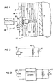
- the device 10 comprises a piezoelectric crystal 22.
- the crystal 22 may, for example, be quartz.
- the crystal 22 includes electrodes or plates 24 and 26.
- the piezoelectric axis is selected to extend between the electrodes 24 and 26 so that the crystal 22 has electrode faces which are so- called X-cut.
- the electrodes 24, 26 of the crystal 22 are connected to a network 28 to be described hereinunder.
- the network 28 is, in tum, connected to a capacitor 30 having a pair of spaced plate members 32 and 34.
- the space between the plate members 32, 34 is exposed to the ambient in the insulation layer 12 on one side of the outer wall 16.
- Plate members 32 and 34 are each formed of a plurality of parallel and interspaced plates.
- the ' piezoelectric crystal 22 is excited by an ultrasonic transducer 36 which is connected to an electronic instrument 38.
- Ultrasonic instrument 38 and transducer 36 are of known type and discussed for example in the publication STEAM, ITS GENERATION AND USE, 39th edition, 1978, The Babcock & Wilcox Company.
- the sonic waves pass through wall 16 and vibrate piezoelectric crystal 22.
- piezoelectric crystal 22 is bonded to and sonically coupled with the inner surface of wall 16.
- the ultrasonic wave is then converted into an electrical signal having the same frequency which is processed through network 28 and applied to capacitor 30. Since moisture content of the ambient within the insulation layer 12 affects the capacitance C of capacitor 30, the impedance of the network inside the annulus is affected. This change in impedance can be detected by electronic instrument 38 using transducer 36 by a signal being provided upon excitation thereof at its resonant frequency. With a moisture-free desired ambience within insulation layer 12, one response is obtained, whereas, with moisture in layer 12, which indicates a failure or degradation of insulation, a different response is obtained.
- FIG. 2 one example of network 28 is a parallel connected inductor 40 having an inductance L.
- Capacitor 30 is shown to be variable, which variation is caused by any change in the ambient of the insulation layer, in particular its moisture content.
- the network of Fig. 2 functions as an oscillator having a natural or resonant frequency Wo. This frequency is established according to the following relationship:
- the natural or resonant frequency is known. With electronic instrument 38 and transducer 36, exciting piezoelectric crystal 22 at that natural frequency, a peak in the network response will be generated. If the natural frequency of the circuit in Fig. 2 drifts from the moisture-free value, in particular if the capacitance decreases due to an increase in moisture, an increased natural frequency will be produced which will require a shifting of the frequency applied to piezoelectric 22, before resonance is determined.
- Electronic instrument 38 for this purpose, can be provided with a sweep frequency modulating pulse generator and an automatic peak signal detector. An example- of such equipment is known as the Tektronix model 504..
- the change in capacitance tunes the piezoelectric crystal to thus provide a response which can be sensed for measurement of moisture content.
- a voltage generated at the crystal activates the network.
- a detector detects when the voltage is built up to a certain level and switches bock for the oscillator to send a signal back out and its frequency read.
- any other moisture sensitive impedance means can be used which changes impedance with change in moisture.
- Other devices can for example be a moisture sensitive resistor or a lithium chloride humidity cell. Impedance is meant to include non-linear as well as linear electrical characteristics.
- ultrasonic and sonic are used interchangeably herein and are meant to mean not only sound or pressure waves which are within the range of hearing but pressure waves which are above and below the range of hearing and generally any pressure waves which can be transmitted through a medium.
- the annular space between the inner and outer tubes or tubulars may advantageously be filled with fibrous or layered insulation, and/or evacuated to establish a thermal barrier.
- the space, when evacuated, may also be provided with a getter material which absorbs gases that may migrate into the space, to maintain the vacuum.
- gases include hydrogen from corrosion of the outer tube and N 2 , CO or 0 2 which is outgassed from the inner tube.
- the getter material e.g. titanium
- the getter material is placed adjacent the inner tube so as to be exposed to the elevated steam temperature of 204°C to 371°C (400°F to 700°F), and thus activated to more effectively absorb the gases.
Landscapes
- Chemical & Material Sciences (AREA)
- General Physics & Mathematics (AREA)
- Physics & Mathematics (AREA)
- Electrochemistry (AREA)
- Health & Medical Sciences (AREA)
- Life Sciences & Earth Sciences (AREA)
- Analytical Chemistry (AREA)
- Biochemistry (AREA)
- General Health & Medical Sciences (AREA)
- Chemical Kinetics & Catalysis (AREA)
- Immunology (AREA)
- Pathology (AREA)
- Investigating Or Analyzing Materials By The Use Of Ultrasonic Waves (AREA)
- Investigating Or Analyzing Materials By The Use Of Electric Means (AREA)
Priority Applications (1)
| Application Number | Priority Date | Filing Date | Title |
|---|---|---|---|
| AT83305013T ATE34846T1 (de) | 1982-08-31 | 1983-08-31 | Verfahren und vorrichtungen zur messung der feuchtigkeit. |
Applications Claiming Priority (2)
| Application Number | Priority Date | Filing Date | Title |
|---|---|---|---|
| US06/413,286 US4491784A (en) | 1982-08-31 | 1982-08-31 | Piezoelectric moisture measuring device |
| US413286 | 1995-03-30 |
Publications (3)
| Publication Number | Publication Date |
|---|---|
| EP0106470A2 true EP0106470A2 (de) | 1984-04-25 |
| EP0106470A3 EP0106470A3 (en) | 1985-05-02 |
| EP0106470B1 EP0106470B1 (de) | 1988-06-01 |
Family
ID=23636649
Family Applications (1)
| Application Number | Title | Priority Date | Filing Date |
|---|---|---|---|
| EP83305013A Expired EP0106470B1 (de) | 1982-08-31 | 1983-08-31 | Verfahren und Vorrichtungen zur Messung der Feuchtigkeit |
Country Status (12)
| Country | Link |
|---|---|
| US (1) | US4491784A (de) |
| EP (1) | EP0106470B1 (de) |
| JP (1) | JPS5965247A (de) |
| KR (1) | KR900005478B1 (de) |
| AR (1) | AR241330A1 (de) |
| AT (1) | ATE34846T1 (de) |
| BR (1) | BR8304589A (de) |
| CA (1) | CA1198908A (de) |
| DE (1) | DE3376878D1 (de) |
| IN (1) | IN162581B (de) |
| MX (1) | MX154786A (de) |
| PH (1) | PH20323A (de) |
Cited By (1)
| Publication number | Priority date | Publication date | Assignee | Title |
|---|---|---|---|---|
| GB2496136A (en) * | 2011-11-01 | 2013-05-08 | Isis Innovation | Passive capacitive moisture detector |
Families Citing this family (9)
| Publication number | Priority date | Publication date | Assignee | Title |
|---|---|---|---|---|
| JPS63226506A (ja) * | 1987-03-16 | 1988-09-21 | Matsushita Electric Ind Co Ltd | 触媒燃焼装置 |
| WO2000052516A2 (en) | 1999-03-01 | 2000-09-08 | Boston Innovative Optics, Inc. | System and method for increasing the depth of focus of the human eye |
| KR100815294B1 (ko) | 2006-06-28 | 2008-03-19 | 한국폴리텍Iv대학 산학협력단 | 회복전압법과 유전특성을 이용한 수분량 검출 장치 및 방법 |
| US20110133755A1 (en) * | 2009-12-08 | 2011-06-09 | Delphi Technologies, Inc. | System and Method of Occupant Detection with a Resonant Frequency |
| US9032792B2 (en) * | 2012-01-19 | 2015-05-19 | Nalco Company | Fouling reduction device and method |
| EP2785296B1 (de) | 2011-12-02 | 2018-06-20 | AcuFocus, Inc. | Augenmaske mit selektiver spektraler übertragung |
| US9204962B2 (en) | 2013-03-13 | 2015-12-08 | Acufocus, Inc. | In situ adjustable optical mask |
| US9427922B2 (en) | 2013-03-14 | 2016-08-30 | Acufocus, Inc. | Process for manufacturing an intraocular lens with an embedded mask |
| CN105452853B (zh) * | 2013-08-13 | 2018-01-30 | 株式会社村田制作所 | 温湿度传感器 |
Family Cites Families (6)
| Publication number | Priority date | Publication date | Assignee | Title |
|---|---|---|---|---|
| US2536111A (en) * | 1945-07-04 | 1951-01-02 | Karl S Van Dyke | Dew point hygrometer |
| US3256482A (en) * | 1962-02-23 | 1966-06-14 | Nat Tank Co | Basic sediment and water monitor utilizing a plurality of selectable compensating capacitors in a resonant detecting circuit |
| GB1340703A (en) * | 1970-04-22 | 1973-12-12 | Atomic Energy Authority Uk | Transducers for measuring apparatus |
| JPS5255580A (en) * | 1975-10-30 | 1977-05-07 | Matsushita Electric Ind Co Ltd | Humidity sensor |
| US4312228A (en) * | 1979-07-30 | 1982-01-26 | Henry Wohltjen | Methods of detection with surface acoustic wave and apparati therefor |
| JPS56119474A (en) * | 1980-02-25 | 1981-09-19 | Nippon Denso Co | Device for responding to refrigerang amount for refrigerant circulating apparatus |
-
1982
- 1982-08-31 US US06/413,286 patent/US4491784A/en not_active Expired - Fee Related
-
1983
- 1983-08-25 BR BR8304589A patent/BR8304589A/pt not_active IP Right Cessation
- 1983-08-26 JP JP58155160A patent/JPS5965247A/ja active Granted
- 1983-08-26 CA CA000435500A patent/CA1198908A/en not_active Expired
- 1983-08-29 PH PH29465A patent/PH20323A/en unknown
- 1983-08-29 IN IN1045/CAL/83A patent/IN162581B/en unknown
- 1983-08-30 KR KR1019830004060A patent/KR900005478B1/ko not_active Expired
- 1983-08-30 AR AR83294054A patent/AR241330A1/es active
- 1983-08-31 AT AT83305013T patent/ATE34846T1/de not_active IP Right Cessation
- 1983-08-31 DE DE8383305013T patent/DE3376878D1/de not_active Expired
- 1983-08-31 MX MX198578A patent/MX154786A/es unknown
- 1983-08-31 EP EP83305013A patent/EP0106470B1/de not_active Expired
Cited By (1)
| Publication number | Priority date | Publication date | Assignee | Title |
|---|---|---|---|---|
| GB2496136A (en) * | 2011-11-01 | 2013-05-08 | Isis Innovation | Passive capacitive moisture detector |
Also Published As
| Publication number | Publication date |
|---|---|
| KR840006070A (ko) | 1984-11-21 |
| JPH0257865B2 (de) | 1990-12-06 |
| PH20323A (en) | 1986-11-25 |
| IN162581B (de) | 1988-06-11 |
| CA1198908A (en) | 1986-01-07 |
| KR900005478B1 (ko) | 1990-07-30 |
| DE3376878D1 (en) | 1988-07-07 |
| JPS5965247A (ja) | 1984-04-13 |
| US4491784A (en) | 1985-01-01 |
| MX154786A (es) | 1987-12-11 |
| ATE34846T1 (de) | 1988-06-15 |
| AR241330A1 (es) | 1992-05-29 |
| BR8304589A (pt) | 1984-04-03 |
| EP0106470A3 (en) | 1985-05-02 |
| EP0106470B1 (de) | 1988-06-01 |
Similar Documents
| Publication | Publication Date | Title |
|---|---|---|
| US4491784A (en) | Piezoelectric moisture measuring device | |
| US4302826A (en) | Resonant acoustic transducer system for a well drilling string | |
| US4283780A (en) | Resonant acoustic transducer system for a well drilling string | |
| US10526884B2 (en) | Systems and methods for monitoring cement quality in a cased well environment with integrated chips | |
| US2425868A (en) | Method and apparatus for logging drill holes | |
| CN109477378B (zh) | 使用电阻元件沿井眼感测温度的装置和方法 | |
| BR112018074168B1 (pt) | Aparelho para uso na detecção de temperatura em um furo de poço, poço compreendendo um aparelho de poço e método para calibrar um aparelho | |
| BR112018074151B1 (pt) | Aparelho para detectar temperatura de furo de poço, poço compreendendo um aparelho de detecção de temperatura de furo de poço e método para calibrar um aparelho | |
| EA037930B1 (ru) | Аппарат для регистрации температуры вдоль ствола скважины | |
| EP2603664B1 (de) | Verfahren und vorrichtung zur messung einer prozessvariablen eines fluids in einem bohrloch | |
| RU2733343C2 (ru) | Способ и система для измерения параметров в скважине | |
| US2783449A (en) | Seismic velocity measurement | |
| US4673652A (en) | Method of testing and reconditioning insulating tubular conduits | |
| US20130257628A1 (en) | System and method for measurement incorporating a crystal resonator | |
| US3213414A (en) | Acoustic transducer with pressure equalizing cover | |
| US4516520A (en) | Method and apparatus of thermal detection using bonded coupon | |
| EP0033192A1 (de) | System zur akustischen Datenweiterleitung entlang einem Bohrloch-Gestängestrang | |
| US2421423A (en) | Method and apparatus for taking physical measurements in boreholes | |
| AU2015270330A1 (en) | Method and system for operating and monitoring a well for extracting or storing fluid | |
| US9625338B2 (en) | Passive pressure sensing using sensor with resonator having bridged ends | |
| RU2305172C1 (ru) | Автоматизированный саморегулирующийся нагреватель для прогрева текучей среды в скважине | |
| RU2847787C1 (ru) | Скважинный датчик давления на акустически связанных кварцевых резонаторах и способ измерения внутрискважинного давления с его использованием | |
| RU166657U1 (ru) | Комплексный прибор для исследования скважин | |
| EA037631B1 (ru) | Способ определения физических величин в скважине на основе пьезорезонансных датчиков без электроники и устройство для его осуществления | |
| RU136487U1 (ru) | Акустическая телеметрическая система мониторинга состояния наблюдательной скважины |
Legal Events
| Date | Code | Title | Description |
|---|---|---|---|
| PUAI | Public reference made under article 153(3) epc to a published international application that has entered the european phase |
Free format text: ORIGINAL CODE: 0009012 |
|
| AK | Designated contracting states |
Designated state(s): AT BE CH DE FR GB IT LI LU NL SE |
|
| PUAL | Search report despatched |
Free format text: ORIGINAL CODE: 0009013 |
|
| AK | Designated contracting states |
Designated state(s): AT BE CH DE FR GB IT LI LU NL SE |
|
| 17P | Request for examination filed |
Effective date: 19850601 |
|
| 17Q | First examination report despatched |
Effective date: 19860915 |
|
| ITF | It: translation for a ep patent filed | ||
| GRAA | (expected) grant |
Free format text: ORIGINAL CODE: 0009210 |
|
| AK | Designated contracting states |
Kind code of ref document: B1 Designated state(s): AT BE CH DE FR GB IT LI LU NL SE |
|
| REF | Corresponds to: |
Ref document number: 34846 Country of ref document: AT Date of ref document: 19880615 Kind code of ref document: T |
|
| REF | Corresponds to: |
Ref document number: 3376878 Country of ref document: DE Date of ref document: 19880707 |
|
| ET | Fr: translation filed | ||
| PLBE | No opposition filed within time limit |
Free format text: ORIGINAL CODE: 0009261 |
|
| STAA | Information on the status of an ep patent application or granted ep patent |
Free format text: STATUS: NO OPPOSITION FILED WITHIN TIME LIMIT |
|
| 26N | No opposition filed | ||
| PGFP | Annual fee paid to national office [announced via postgrant information from national office to epo] |
Ref country code: GB Payment date: 19910717 Year of fee payment: 9 |
|
| PGFP | Annual fee paid to national office [announced via postgrant information from national office to epo] |
Ref country code: AT Payment date: 19910726 Year of fee payment: 9 |
|
| PGFP | Annual fee paid to national office [announced via postgrant information from national office to epo] |
Ref country code: LU Payment date: 19910801 Year of fee payment: 9 |
|
| PGFP | Annual fee paid to national office [announced via postgrant information from national office to epo] |
Ref country code: FR Payment date: 19910822 Year of fee payment: 9 |
|
| PGFP | Annual fee paid to national office [announced via postgrant information from national office to epo] |
Ref country code: SE Payment date: 19910828 Year of fee payment: 9 Ref country code: DE Payment date: 19910828 Year of fee payment: 9 |
|
| ITTA | It: last paid annual fee | ||
| PGFP | Annual fee paid to national office [announced via postgrant information from national office to epo] |
Ref country code: NL Payment date: 19910831 Year of fee payment: 9 |
|
| PGFP | Annual fee paid to national office [announced via postgrant information from national office to epo] |
Ref country code: BE Payment date: 19910912 Year of fee payment: 9 |
|
| PGFP | Annual fee paid to national office [announced via postgrant information from national office to epo] |
Ref country code: CH Payment date: 19910923 Year of fee payment: 9 |
|
| EPTA | Lu: last paid annual fee | ||
| PG25 | Lapsed in a contracting state [announced via postgrant information from national office to epo] |
Ref country code: LU Free format text: LAPSE BECAUSE OF NON-PAYMENT OF DUE FEES Effective date: 19920831 Ref country code: LI Effective date: 19920831 Ref country code: GB Effective date: 19920831 Ref country code: CH Effective date: 19920831 Ref country code: BE Effective date: 19920831 Ref country code: AT Effective date: 19920831 |
|
| PG25 | Lapsed in a contracting state [announced via postgrant information from national office to epo] |
Ref country code: SE Effective date: 19920901 |
|
| BERE | Be: lapsed |
Owner name: THE BABCOCK & WILCOX CY Effective date: 19920831 |
|
| PG25 | Lapsed in a contracting state [announced via postgrant information from national office to epo] |
Ref country code: NL Effective date: 19930301 |
|
| NLV4 | Nl: lapsed or anulled due to non-payment of the annual fee | ||
| GBPC | Gb: european patent ceased through non-payment of renewal fee |
Effective date: 19920831 |
|
| PG25 | Lapsed in a contracting state [announced via postgrant information from national office to epo] |
Ref country code: FR Effective date: 19930430 |
|
| REG | Reference to a national code |
Ref country code: CH Ref legal event code: PL |
|
| PG25 | Lapsed in a contracting state [announced via postgrant information from national office to epo] |
Ref country code: DE Effective date: 19930501 |
|
| REG | Reference to a national code |
Ref country code: FR Ref legal event code: ST |
|
| EUG | Se: european patent has lapsed |
Ref document number: 83305013.1 Effective date: 19930406 |