EP0105934B1 - Intake system of an internal-combustion engine - Google Patents
Intake system of an internal-combustion engine Download PDFInfo
- Publication number
- EP0105934B1 EP0105934B1 EP82107552A EP82107552A EP0105934B1 EP 0105934 B1 EP0105934 B1 EP 0105934B1 EP 82107552 A EP82107552 A EP 82107552A EP 82107552 A EP82107552 A EP 82107552A EP 0105934 B1 EP0105934 B1 EP 0105934B1
- Authority
- EP
- European Patent Office
- Prior art keywords
- intake
- intake passage
- passage
- passages
- auxiliary
- Prior art date
- Legal status (The legal status is an assumption and is not a legal conclusion. Google has not performed a legal analysis and makes no representation as to the accuracy of the status listed.)
- Expired
Links
Images


Classifications
-
- F—MECHANICAL ENGINEERING; LIGHTING; HEATING; WEAPONS; BLASTING
- F02—COMBUSTION ENGINES; HOT-GAS OR COMBUSTION-PRODUCT ENGINE PLANTS
- F02M—SUPPLYING COMBUSTION ENGINES IN GENERAL WITH COMBUSTIBLE MIXTURES OR CONSTITUENTS THEREOF
- F02M35/00—Combustion-air cleaners, air intakes, intake silencers, or induction systems specially adapted for, or arranged on, internal-combustion engines
- F02M35/10—Air intakes; Induction systems
- F02M35/10242—Devices or means connected to or integrated into air intakes; Air intakes combined with other engine or vehicle parts
- F02M35/10308—Equalizing conduits, e.g. between intake ducts or between plenum chambers
-
- F—MECHANICAL ENGINEERING; LIGHTING; HEATING; WEAPONS; BLASTING
- F02—COMBUSTION ENGINES; HOT-GAS OR COMBUSTION-PRODUCT ENGINE PLANTS
- F02F—CYLINDERS, PISTONS OR CASINGS, FOR COMBUSTION ENGINES; ARRANGEMENTS OF SEALINGS IN COMBUSTION ENGINES
- F02F1/00—Cylinders; Cylinder heads
- F02F1/24—Cylinder heads
- F02F1/42—Shape or arrangement of intake or exhaust channels in cylinder heads
- F02F1/4214—Shape or arrangement of intake or exhaust channels in cylinder heads specially adapted for four or more valves per cylinder
-
- F—MECHANICAL ENGINEERING; LIGHTING; HEATING; WEAPONS; BLASTING
- F02—COMBUSTION ENGINES; HOT-GAS OR COMBUSTION-PRODUCT ENGINE PLANTS
- F02M—SUPPLYING COMBUSTION ENGINES IN GENERAL WITH COMBUSTIBLE MIXTURES OR CONSTITUENTS THEREOF
- F02M35/00—Combustion-air cleaners, air intakes, intake silencers, or induction systems specially adapted for, or arranged on, internal-combustion engines
- F02M35/10—Air intakes; Induction systems
- F02M35/10006—Air intakes; Induction systems characterised by the position of elements of the air intake system in direction of the air intake flow, i.e. between ambient air inlet and supply to the combustion chamber
- F02M35/10072—Intake runners
-
- F—MECHANICAL ENGINEERING; LIGHTING; HEATING; WEAPONS; BLASTING
- F02—COMBUSTION ENGINES; HOT-GAS OR COMBUSTION-PRODUCT ENGINE PLANTS
- F02M—SUPPLYING COMBUSTION ENGINES IN GENERAL WITH COMBUSTIBLE MIXTURES OR CONSTITUENTS THEREOF
- F02M35/00—Combustion-air cleaners, air intakes, intake silencers, or induction systems specially adapted for, or arranged on, internal-combustion engines
- F02M35/10—Air intakes; Induction systems
- F02M35/104—Intake manifolds
- F02M35/108—Intake manifolds with primary and secondary intake passages
-
- F—MECHANICAL ENGINEERING; LIGHTING; HEATING; WEAPONS; BLASTING
- F02—COMBUSTION ENGINES; HOT-GAS OR COMBUSTION-PRODUCT ENGINE PLANTS
- F02B—INTERNAL-COMBUSTION PISTON ENGINES; COMBUSTION ENGINES IN GENERAL
- F02B1/00—Engines characterised by fuel-air mixture compression
- F02B1/02—Engines characterised by fuel-air mixture compression with positive ignition
- F02B1/04—Engines characterised by fuel-air mixture compression with positive ignition with fuel-air mixture admission into cylinder
-
- F—MECHANICAL ENGINEERING; LIGHTING; HEATING; WEAPONS; BLASTING
- F02—COMBUSTION ENGINES; HOT-GAS OR COMBUSTION-PRODUCT ENGINE PLANTS
- F02B—INTERNAL-COMBUSTION PISTON ENGINES; COMBUSTION ENGINES IN GENERAL
- F02B31/00—Modifying induction systems for imparting a rotation to the charge in the cylinder
- F02B2031/006—Modifying induction systems for imparting a rotation to the charge in the cylinder having multiple air intake valves
-
- F—MECHANICAL ENGINEERING; LIGHTING; HEATING; WEAPONS; BLASTING
- F02—COMBUSTION ENGINES; HOT-GAS OR COMBUSTION-PRODUCT ENGINE PLANTS
- F02B—INTERNAL-COMBUSTION PISTON ENGINES; COMBUSTION ENGINES IN GENERAL
- F02B2275/00—Other engines, components or details, not provided for in other groups of this subclass
- F02B2275/18—DOHC [Double overhead camshaft]
-
- F—MECHANICAL ENGINEERING; LIGHTING; HEATING; WEAPONS; BLASTING
- F02—COMBUSTION ENGINES; HOT-GAS OR COMBUSTION-PRODUCT ENGINE PLANTS
- F02F—CYLINDERS, PISTONS OR CASINGS, FOR COMBUSTION ENGINES; ARRANGEMENTS OF SEALINGS IN COMBUSTION ENGINES
- F02F1/00—Cylinders; Cylinder heads
- F02F1/24—Cylinder heads
- F02F2001/244—Arrangement of valve stems in cylinder heads
- F02F2001/245—Arrangement of valve stems in cylinder heads the valve stems being orientated at an angle with the cylinder axis
-
- F—MECHANICAL ENGINEERING; LIGHTING; HEATING; WEAPONS; BLASTING
- F02—COMBUSTION ENGINES; HOT-GAS OR COMBUSTION-PRODUCT ENGINE PLANTS
- F02M—SUPPLYING COMBUSTION ENGINES IN GENERAL WITH COMBUSTIBLE MIXTURES OR CONSTITUENTS THEREOF
- F02M35/00—Combustion-air cleaners, air intakes, intake silencers, or induction systems specially adapted for, or arranged on, internal-combustion engines
- F02M35/10—Air intakes; Induction systems
- F02M35/104—Intake manifolds
- F02M35/108—Intake manifolds with primary and secondary intake passages
- F02M35/1085—Intake manifolds with primary and secondary intake passages the combustion chamber having multiple intake valves
Landscapes
- Engineering & Computer Science (AREA)
- Chemical & Material Sciences (AREA)
- Combustion & Propulsion (AREA)
- Mechanical Engineering (AREA)
- General Engineering & Computer Science (AREA)
- Control Of Throttle Valves Provided In The Intake System Or In The Exhaust System (AREA)
- Cylinder Crankcases Of Internal Combustion Engines (AREA)
Description
- The invention relates to an internal combustion engine and in particular to an improved intake system for an internal combustion engine.
- There are internal combustion engines, for example of four-cycle type, which have their intake valves located in the downstream end of their intake passages such that the respective valve stems are intersecting the flow of intake air. Internal combustion engines of this type experience a phenomenon that the intake air flowing through the intake passage is obstructed in the downstream end of said passage by the stem and guide of said intake valve so that the intake air flow is disturbed immediately downstream of the valve stem with respect to the flow direction.
- Said air flow disturbances result in a loss of intake air thereby creating the problem that the intake air amount or intake air pressure within the cylinder to be charged is reduced resulting in a corresponding reduction in the output performance of the internal combustion engine.
- US-A-4 186 706 describes an internal combustion engine of the type in which a first and a second intake passage and an exhaust passage are formed in each cylinder head and an intake valve is arranged at the downstream end of the first intake passage such as to have its valve stem intersecting the flow of intake air into a combustion chamber. The second intake passage has an effective area set smaller than that of the first intake passage and opens into the first intake passage immediately downstream of said intake valve stem such that it is directed in the transversal direction to the direction of the first intake passage while intersecting same. Furthermore, a throttle valve is disposed upstream of said intake valve within the first intake passage such that it is closed in the low or intermediate speed running operation of the engine. In the intake system as shown in US-A-4 186 706, there is a transverse offset between the opening of the secondary (auxiliary) intake passage and the axis of the valve stem.
- The object of the claimed invention is to design an intake system for internal combustion engines such that the disturbances of the intake air flow immediately downstream of the valve stem of the intake valve with respect to the flow direction are eliminated.
- This object is solved by the subject-matter of claim 1 which specifies the inventive location of the inlet point of the auxiliary intake passage. Six ways of carrying out the invention are described in detail below with reference to the drawings which illustrate these six specific embodiments, in which:
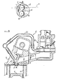
- Fig. 1 is a sectional view showing the intake system according to the present invention;
- Fig. 2 is a view taken along arrow II of Fig. 1;
- Fig. 3 is a sectional view showing the third embodiment;
- Fig. 4 is a sectional view showing the third embodiment;
- Fig. 5 is a sectional view showing the fourth embodiment;
- Fig. 6 is a section taken along line VI-VI of Fig. 5;
- Fig. 7 is a sectional view showing the fifth embodiment;
- Fig. 8 is a view taken along arrow VIII of Fig. 7; and
- Fig. 9 is a sectional view showing the sixth embodiment.
- The figures show an intake system of a four-cycle engine. This four-cycle engine A, A' is equipped with a plurality of cylinders a, a' of which one is shown in the drawings.
- Each cylinder comprises a cylinder head b, b' and a piston (c, c').
- Reference numeral 1 denotes a recess which is formed in the upper end of the aforementioned cylinder head b. This recess defines a
combustion chamber 2 together with the upper end of the piston c shown at its top dead centre. -
Reference numerals aforementioned combustion chamber 2 to communicate with thecombustion chamber 2 throughintake ports 5 andexhaust ports 6, respectively. -
Reference numeral 7 indicates intake valves for opening and closing theaforementioned intake ports 5, and numeral 8 indicates exhaust valves for opening and closing theexhaust ports 6. - As shown in Fig. 2 in the illustrated embodiment, each cylinder head is provided with two
intake valves 7 and with two exhaust valves 8 so that twointake passages 3 and twoexhaust passages 4 are required. - These intake and
exhaust valves 7 and 8 are so arranged downstream of theintake passages 3 and theexhaust passages 4 as to have their respective valve stems 7a and 8a intersecting the flows of the intake air and the exhaust gas, respectively, and have their lower ends facing the inside of thecombustion chamber 2 and corresponding to theintake ports 5 and theexhaust ports 6, respectively, and their valve stems 7a and 8a slidably guided within the wall of the cylinder head b by means ofguides - The four-cycle engine A so far described now experiences a phenomenon that the flow of the intake air is blocked in the
intake passage 3 by theintake valves 7, specifically, by the valve stems 7a and by theguides 9 so that the intake air flow is disturbed immediately downstream of said valve stems 7a with respect to the flow direction. As means for eliminating that phenomenon, it is known to provideauxiliary intake passages 11. - Each of these
auxiliary intake passages 11 has its effective area set smaller than that of theintake passage 3 and opens into saidpassage 3 immediately downstream of the intersection of the valve stem 7a into the intake passage with respect to the flow direction, i.e. the opening of each auxiliary intake passage is located in a plane comprising the axis of the valve stem and such that the opening is directed in the transverse direction to the direction of the first intake passage while intersecting same. Furthermore, saidauxiliary intake passage 11 opens at the outside of the curved direction, such that it is directed toward thecombustion chamber 2, i.e. toward the outer circumferential portion of the same. - Moreover, the aforementioned
auxiliary intake passage 11 extends through the wall of the cylinder head b and is connected through ashort pipe 12 and a connectingpipe 13 with acommunication pipe 14. - This
communication pipe 14 has a length which extends over the respective cylinders of the engine A so that theintake passages 3 of the respective cylinders are allowed to communicate through theauxiliary intake passages 11 of the respective cylinders which are made to communicate by connecting thosepassages 11 with saidpipe 14, as has been described in the above. - Since the respective cylinders of the aforementioned engine A now have different stroke phases, the vacuum of one cylinder in the intake stroke is exerted upon the
intake passages 3 of the cylinders in a stroke other than the intake stroke so that the intake air in theintake passages 3 of the cylinder in the stroke other than the intake stroke is sucked by the vacuum to flow through theauxiliary intake passages 11 and thecommunication pipe 14 into theauxiliary intake passages 11 of the cylinder in the intake stroke. - Moreover, the intake air coming from those
auxiliary intake passages 11 flows at a high rate into the cylinder a via those portions of theintake passages 3, which are located just downstream of the valve stems 7a. - As has been described hereinbefore, the intake air is prevented from residing in the
intake passages 3 of each cylinder, and the disturbances of the intake air immediately downstream of the valve stems 7a are settled down and eliminated by the intake air which flows from theauxiliary intake passages 11, thus augmenting the charges of the cylinder a with the intake air. - Other embodiments of the present invention will now be described with reference to Figs. 3 to 9.
- Incidentally, in order to simplify the explanation, parts identical to those of the foregoing embodiment are indicated at identical reference characters, and their explanations are omitted.
- First of all, in an embodiment shown in Fig. 3 the
auxiliary intake passages 11 of each cylinder are connected with aplenum chamber 15. - This
plenum chamber 15 has a relatively large capacity and is provided independently for each cylinder. As a result, theplenum chamber 15 performs a function to temporarily reserve the intake air for a time period from the end of the intake stroke to the start of the subsequent intake stroke of the cylinder. - More specifically the vacuum, which has been applied to the
plenum chamber 15 via theauxiliary intake passages 11 during the intake stroke, is left active after the end of the intake stroke so that the intake air of theintake passages 3 is sucked by that vacuum and reserved in theplenum chamber 15. - On the other hand, the intake air reserved in the
plenum chamber 15 is returned during the subsequent intake stroke from theauxiliary intake passages 11 to theintake passages 3. - As a result, the intake air is allowed to continuously flow without residing in the
intake passages 3, the intake air in theplenum chamber 15 merges into the intake air of theintake passages 3 immediately downstream of the valve stems 7a by way of theauxiliary intake passages 11 so that the intake air is prevented from being disturbed just downstream of said valve stems 7a thereby to augment the charge of the cylinder a with the intake air. - Moreover, the intake system of the embodiment under discussion can be attached to a single-cylinder engine because its
plenum chamber 15 is provided independently for each cylinder. - Next, in another embodiment shown in Fig. 4 the
auxiliary intake passages 11 are connected with theintake passage 3 upstream of the valve stems 7a by way of a by-pass conduit 16 while by- passing said valve stems 7a. - Thus, in this embodiment, the intake air flowing through the
intake passages 3 is divided into the by-pass conduit 16 so that the intake air introduced from said conduit 16 into theauxiliary intake passages 11 merges into the intake air flowing in theintake passages 3 immediately downstream of the valve stems 7a. As a result, the disturbances of the intake air immediately downstream of the valve stems 7a are settled down to augment the intake air the cylinder a is to be charged with. - Incidentally, the intake system of the embodiment thus far described can also be applied to a single-cylinder engine because the bypass conduit is provided for each cylinder.
- Moreover, since the two
intake passages 3 of each cylinder are made to merge into each other at their upstream portions, the merging portions of the respective cylinders may be made to communicate with a single pipe connected with the by-pass conduit. - With this modification, into the by-pass conduit 16, there flow not only the intake air which is divided from the
intake passage 3 but also the intake air which comes from theintake passage 3 of the cylinder in a stroke other than the intake stroke, so that the flow rate of the intake air can be augmented. - Next, another embodiment shown in Figs. 5 and 6 is modified from the foregoing embodiment shown in Fig. 1 and 2 such that there is provided a
throttle valve 17 which is made operative to close one of theauxiliary intake passages 11 of each cylinder when the engine A is in a low or intermediate speed running operation. - That
throttle valve 17 is disposed in a conduit 18, which connects one of theauxiliary intake passages 11 and thecommunication pipe 14, and is adapted to be closed when in the low or intermediate speed running operation of the engine A and opened when in a high speed running operation. -
Reference numeral 19 indicates a throttle valve which is disposed at the upstream side of theintake passage 3 of each cylinder and which is adapted to be closed similarly to theaforementioned throttle valve 17 when in the low or intermediate speed running operation of the engine Athereby to regulate the flow of the intake air from theintake passage 3 into the cylinder a. - Incidentally, the
throttle valve 19 thus far described is used in the embodiment in which the intake air is fed to the respective cylinders by the action of a single carburetor (although not shown). Therefore, thethrottle valve 19 can be replaced by the throttle valves of the respective carburetors in the embodiment in which the respective cylinders are independently equipped with the carburetors. - In the embodiment under discussion, too, it is similar to the foregoing embodiments that the disturbances of the intake air in the
intake passage 3 immediately downstream of the valve stem 7a can be eliminated. This embodiment can enjoy the following additional operation. - Specifically, during the low or intermediate speed running operation of the engine A, the
throttle valves intake passage 3 of each cylinder and in one of theauxiliary intake passages 11 are closed. - As a result, the cylinder a during the intake stroke is fed with the intake air exclusively from the
auxiliary intake passage 11 which is open. However, since theauxiliary intake passages 11 are directed toward the outer circumferential portion of thecombustion chamber 2 and have the smaller effective area, the intake air coming from one of theauxiliary intake passages 11 flow at a high rate in the tangential direction into the cylinder a so that it can generate a swirling flow in the cylinder a to effect the combustion with the intake air in thecombustion chamber 2 at a high rate and in a stable manner thereby to improve the combustion efficiency. - Next, another embodiment shown in Figs. 7 and 8, is different in the type of the engine, specifically, in the intake and exhaust systems of the engine from those of the foregoing embodiments.
- More specifically, the engine A' in this embodiment is the so-called "counterflow type multicylinder engine", in which an intake passage 3' and an exhaust passage 4' formed in the cylinder head b' of each cylinder are arranged side by side and have their port 5' and 6' respectively in a common plane.
- Both the aforementioned two passages 3' and 4' are directed toward the outer circumferential portion of a combustion chamber2' through their intake and exhaust port 5' and 6', respectively.
-
Reference numeral 20 indicates a carburetor which is connected to the upstream end of the intake passage 3' of each cylinder so that it feeds the respective cylinders with the intake air. - As shown in Fig. 8, the aforementioned engine A' is equipped similarly to the foregoing embodiments with an auxiliary intake passage 11' which opens into the first intake passage 3' immediately downstream of the intersection of the valve stem into the first intake passage with respect to the flow direction; i.e. the opening of said auxiliary intake passage 11' is located in a plane X comprising the axis of the valve stem 7', and such that it is directed in the transverse direction to the direction of the first intake passage 3' while intersecting same. The auxiliary intake passage 11' opens in an outwardly curved portion downstream of the intake passage.
- In other words, the auxiliary intake passage 11' is directed to face the outer circumferential portion of the combustion chamber 2', which is located at the opposite side of the intake passage 3', from the intake port 5' generally in the tangential direction of a cylinder a'.
- Moreover, the auxiliary intake passages 11' of the aforementioned respective cylinders are connected to a communication pipe 14' so that they communicate with one another.
-
Reference numeral 21 indicates a throttle valve which is disposed upstream of the intake valve 7' within the intake passage 3' such that it is closed when in the low or intermediate speed running operation of the engine A'. - Thus, the intake system of this embodiment is similar to the foregoing embodiments in that the possible disturbances of the intake air immediately downstream of valve stems 7a' are eliminated by the intake air coming from the auxiliary intake passages 11' but has the following additional operation.
- Specifically, the intake air is made to flow exclusively through the auxiliary intake passages 11' by closing the
throttle valve 21 in an upstream portion of the intake passages 3' during the slow or intermediate running operation of the engine A'. - Since the auxiliary intake passage 11' is now directed tangentially to the cylinder a', the intake air from said passage 11' establishes the swirling flow in the cylinder a' so that the combustion in the combustion chamber 2' can be maintained at the high rate and in the stable manner thereby to improve the combustion efficiency.
- Next, another embodiment shown in Fig. 9 is modified from the foregoing embodiment of Figs. 7 and 8 such that the communication pipe 14' is connected to the
carburetor 20 by way of aconduit 22. - Thus, in this embodiment, the auxiliary intake passage 11' is directly connected to the
carburetor 20, while by-passing thethrottle valve 21 upstream of the intake passage 3', so that the intake air flows directly from thecarburetor 20 into the auxiliary intake passage 11', even if theaforementioned throttle valve 21 and thethrottle valve 23 of thecarburetor 20 are closed, thereby to establish a more intense swirling flow than those of the foregoing embodiments. - Incidentally, it is similar to the foregoing embodiments that the disturbances of the intake air immediately downstream of the valve stem 7a' are eliminated by the flow of the intake air coming from the auxiliary intake passage 11'.
Claims (3)
Priority Applications (1)
| Application Number | Priority Date | Filing Date | Title |
|---|---|---|---|
| EP82107552A EP0105934B1 (en) | 1982-08-18 | 1982-08-18 | Intake system of an internal-combustion engine |
Applications Claiming Priority (1)
| Application Number | Priority Date | Filing Date | Title |
|---|---|---|---|
| EP82107552A EP0105934B1 (en) | 1982-08-18 | 1982-08-18 | Intake system of an internal-combustion engine |
Publications (2)
| Publication Number | Publication Date |
|---|---|
| EP0105934A1 EP0105934A1 (en) | 1984-04-25 |
| EP0105934B1 true EP0105934B1 (en) | 1987-12-23 |
Family
ID=8189184
Family Applications (1)
| Application Number | Title | Priority Date | Filing Date |
|---|---|---|---|
| EP82107552A Expired EP0105934B1 (en) | 1982-08-18 | 1982-08-18 | Intake system of an internal-combustion engine |
Country Status (1)
| Country | Link |
|---|---|
| EP (1) | EP0105934B1 (en) |
Families Citing this family (9)
| Publication number | Priority date | Publication date | Assignee | Title |
|---|---|---|---|---|
| US4679531A (en) * | 1984-11-08 | 1987-07-14 | Mazda Motor Corporation | Intake system for internal combustion engine |
| GB2204094A (en) * | 1987-04-03 | 1988-11-02 | Ford Motor Co | Multiple intake ducts to i.c. engine cylinder intake valves |
| AT402430B (en) * | 1992-04-09 | 1997-05-26 | Avl Verbrennungskraft Messtech | DIESEL INTERNAL COMBUSTION ENGINE WITH ONE OR MORE ROTATING PISTON |
| IT1260973B (en) * | 1993-08-06 | 1996-04-29 | Ferrari Spa | INTERNAL COMBUSTION ENGINE |
| DE4332198A1 (en) * | 1993-09-22 | 1995-03-23 | Porsche Ag | Internal combustion engine |
| US5950582A (en) * | 1998-06-08 | 1999-09-14 | Ford Global Technologies, Inc. | Internal combustion engine with variable camshaft timing and intake valve masking |
| US5960755A (en) * | 1998-06-09 | 1999-10-05 | Ford Global Technologies, Inc. | Internal combustion engine with variable camshaft timing and variable duration exhaust event |
| US5957096A (en) * | 1998-06-09 | 1999-09-28 | Ford Global Technologies, Inc. | Internal combustion engine with variable camshaft timing, charge motion control valve, and variable air/fuel ratio |
| FR2849108B1 (en) * | 2002-12-19 | 2006-07-14 | Renault Sa | INTERNAL COMBUSTION ENGINE HAVING MEANS FOR VARYING THE INTENSITY OF SWIRL |
Citations (1)
| Publication number | Priority date | Publication date | Assignee | Title |
|---|---|---|---|---|
| DE3024043A1 (en) * | 1979-06-27 | 1981-01-08 | Yamaha Motor Co Ltd | INTAKE SYSTEM FOR AN INTERNAL COMBUSTION ENGINE |
Family Cites Families (6)
| Publication number | Priority date | Publication date | Assignee | Title |
|---|---|---|---|---|
| GB971211A (en) * | ||||
| FR1079530A (en) * | 1952-07-09 | 1954-11-30 | Daimler Benz Ag | Internal combustion engine with top-to-bottom inlet valves |
| CH445945A (en) * | 1967-02-06 | 1967-10-31 | Saurer Ag Adolph | Internal combustion engine |
| US4304211A (en) * | 1976-11-26 | 1981-12-08 | Yamaha Hatsukoki Kabushiki Kaisha | Control of fuel injection type induction system |
| JPS5442525A (en) * | 1977-09-09 | 1979-04-04 | Yamaha Motor Co Ltd | Suction device of engine |
| JPS5840647B2 (en) * | 1978-10-19 | 1983-09-07 | トヨタ自動車株式会社 | Internal combustion engine intake system |
-
1982
- 1982-08-18 EP EP82107552A patent/EP0105934B1/en not_active Expired
Patent Citations (1)
| Publication number | Priority date | Publication date | Assignee | Title |
|---|---|---|---|---|
| DE3024043A1 (en) * | 1979-06-27 | 1981-01-08 | Yamaha Motor Co Ltd | INTAKE SYSTEM FOR AN INTERNAL COMBUSTION ENGINE |
Also Published As
| Publication number | Publication date |
|---|---|
| EP0105934A1 (en) | 1984-04-25 |
Similar Documents
| Publication | Publication Date | Title |
|---|---|---|
| US4726337A (en) | Intake system for multiple intake valve type engines | |
| EP0330302B1 (en) | Engine with variable area intake passages | |
| US20030000211A1 (en) | Method for driving an internal-combustion engine and an internal-combustion engine | |
| US4765285A (en) | Intake system for internal combustion engine | |
| JPH04501595A (en) | internal combustion engine | |
| US4488531A (en) | Plural intake system for supercharged engine | |
| JPH048610B2 (en) | ||
| EP0105934B1 (en) | Intake system of an internal-combustion engine | |
| US4413605A (en) | Intake manifold heating and exhaust gas recirculation system for an internal combustion engine | |
| US5713200A (en) | Exhaust system for a turbocharged internal combustion engine | |
| US5129368A (en) | Intake manifold for an internal combustion engine | |
| US5718195A (en) | Intake pipe for internal combustion engine | |
| JPS5848712A (en) | Air inlet device of internal-combustion engine | |
| US5651344A (en) | Induction and injection system for multi-valve engine | |
| US5253614A (en) | Intake system for engine | |
| WO1999060259A1 (en) | Arrangement for exhaust gas recirculation and internal combustion engine | |
| JPH0263089B2 (en) | ||
| JPH03182623A (en) | Air intake device for internal combustion engine | |
| GB2296037A (en) | Spark ignition engine charge intake system | |
| EP0100790A1 (en) | Intake system of an internal-combustion engine | |
| JPS5713230A (en) | Intake system of internal combustion engine | |
| KR0142898B1 (en) | Apparatus for controlling exhaust rotary flow of multiple cylinder internal combustion engine | |
| JPH0212271Y2 (en) | ||
| JPH0235854B2 (en) | ||
| JPH0263090B2 (en) |
Legal Events
| Date | Code | Title | Description |
|---|---|---|---|
| PUAI | Public reference made under article 153(3) epc to a published international application that has entered the european phase |
Free format text: ORIGINAL CODE: 0009012 |
|
| 17P | Request for examination filed |
Effective date: 19830704 |
|
| AK | Designated contracting states |
Designated state(s): GB IT |
|
| GRAA | (expected) grant |
Free format text: ORIGINAL CODE: 0009210 |
|
| AK | Designated contracting states |
Kind code of ref document: B1 Designated state(s): GB IT |
|
| ITF | It: translation for a ep patent filed |
Owner name: STUDIO GLP S.R.L. |
|
| PLBE | No opposition filed within time limit |
Free format text: ORIGINAL CODE: 0009261 |
|
| STAA | Information on the status of an ep patent application or granted ep patent |
Free format text: STATUS: NO OPPOSITION FILED WITHIN TIME LIMIT |
|
| 26N | No opposition filed | ||
| ITTA | It: last paid annual fee | ||
| PGFP | Annual fee paid to national office [announced via postgrant information from national office to epo] |
Ref country code: GB Payment date: 19960809 Year of fee payment: 15 |
|
| PG25 | Lapsed in a contracting state [announced via postgrant information from national office to epo] |
Ref country code: GB Free format text: LAPSE BECAUSE OF NON-PAYMENT OF DUE FEES Effective date: 19970818 |
|
| GBPC | Gb: european patent ceased through non-payment of renewal fee |
Effective date: 19970818 |