EP0105931B1 - Hot air circulation type cooking device - Google Patents
Hot air circulation type cooking device Download PDFInfo
- Publication number
- EP0105931B1 EP0105931B1 EP83901221A EP83901221A EP0105931B1 EP 0105931 B1 EP0105931 B1 EP 0105931B1 EP 83901221 A EP83901221 A EP 83901221A EP 83901221 A EP83901221 A EP 83901221A EP 0105931 B1 EP0105931 B1 EP 0105931B1
- Authority
- EP
- European Patent Office
- Prior art keywords
- heating chamber
- hot air
- blow
- partition plate
- compartment
- Prior art date
- Legal status (The legal status is an assumption and is not a legal conclusion. Google has not performed a legal analysis and makes no representation as to the accuracy of the status listed.)
- Expired
Links
Images


Classifications
-
- F—MECHANICAL ENGINEERING; LIGHTING; HEATING; WEAPONS; BLASTING
- F24—HEATING; RANGES; VENTILATING
- F24C—DOMESTIC STOVES OR RANGES ; DETAILS OF DOMESTIC STOVES OR RANGES, OF GENERAL APPLICATION
- F24C15/00—Details
- F24C15/32—Arrangements of ducts for hot gases, e.g. in or around baking ovens
- F24C15/322—Arrangements of ducts for hot gases, e.g. in or around baking ovens with forced circulation
Description
- The present invention relates to cooking appliances of the hot air circulation type, and concerns in particular the provision in such an appliance of a deflecting device for deflecting the blowing direction of the hot air as it enters the heating chamber.
- A conventional cooking appliance of the hot air circulation type is equipped with a hot air circulation fan for forcibly circuiating hot air within a heating chamber. An example of this variety is disclosed in the Applicants' earlier-published Specifications JP-A-115,974/1979 and 223,638/1981. More specifically, such an appliance comprises a load heating chamber for storing a heating load, a heating device for heating said load heating chamber, a compartment adjacent to said load heating chamber, a partition plate separating said load heating chamber from said compartment and having blow-out ports and suction ports for circulation of hot air therebetween, a circulating air heating chamber disposed within said compartment and separated from said load heating chamber by said suction ports of said partition plate, pathways for hot air disposed within said compartment leading to said blow-out ports of said partition plate and being constituted by the volume between the walls of said compartment and the walls of said air heating chamber, and a fan housed in said compartment for circulating hot air through said load heating chamber and said compartment via said air heating chamber.
- Another conventional cooking appliance is shown GB-A-2,054,833.
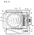
- Fig. 1 is a side view, in section, of a conventional gas cooking appliance of the hot air circulation type. Fig. 2 is a front view, in section, of said appliance. Fig. 3 is a plan view, in section, of said appliance. A
partition plate 2 at the back of a heating chamber 1 is provided withsuction ports 3 disposed substantially in the middle and blow-outports 4 disposed in the right and left peripheral regions. There is provided acompartment 8 having thepartition plate 2, acombustion chamber 5, a circulationair heating chamber 6, and a circulationfan storing chamber 7. Thecombustion chamber 5 is positioned below thecompartment 8 and provided in the lower portion of its peripheral wall with aninlet port 9 for combustion air and is formed in its top wall with acombustion gas passage 10 opening to the circulationair heating chamber 6 and stores twomain burners 11 and apilot burner 12. The circulationair heating chamber 6 is formed so that itspartition wall 8 surrounds thesuction ports 3 of thepartition plate 2, and it is bored with asuction part 14 opposed to the suction side of acirculation fan 13 installed in the circulationfan storing chamber 7. The right and left side walls of the circulationfan storing chamber 7 and thepartition wall 8 extend to thepartition plate 2, forming a blow-outline 15 for hot air communicating with the heating chamber 1. - In the arrangement described above, the hot air flowing out of the heating chamber 1 through the
suction parts 3 formed substantially in the middle of thepartition plate 2 and the combustion gas at high temperature from theburners 11 passing through thecombustion gas passage 10 flow into the circulationair heating chamber 6 and are sucked by thecirculation fan 13 though thesuction port 14 to flow into the blow-outline 15. The two hot flows are sufficiently mixed by the combining and mixing action in this suction and blow-out process and by the stirring action of thecirculation fan 13, providing a hot air flow at high temperature and uniform in temperature throughout. The hot air flow at high temperature moves along the side wall of the circulationfan storing chamber 7 and is blown out into the heating chamber 1 through the blow-outports 4, as shown in Fig. 3. Since the blow-outports 4 are located adjacent the side walls of the heating chamber 1, the hot air flow blowing into the heating chamber 1 through the blow-outports 4 moves along the side wall of the heating chamber 1, striking adoor 16 and joining the other hot air flow, with the joint flow passing substantially through the middle of the heating chamber 1 and sucked through thesuction ports 3.Heating loads 18 placed on the peripheral regions oftrays 18 are subjected directly to the hot air flow at high temperature passing out of the blow-outports 4, so that they are liable to be overheated.Heating loads 18 placed on the middle regions of thetrays 17 are heated by the hot air flow after heating theheating loads 18 placed on the peripheral regions of thetrays 17. Since the hot air flows along the periphery of the heating chamber 1 before it reaches the middle region, it gradually loses some of its heat, producing a difference in the heating degree between the peripheral and middle regions. Further, ifheating loads 18 of substantial height are placed around the periphery, they form an obstacle which makes it difficult for the hot air to flow to the middle region, so that the latter is less heated. Since thetrays 17 are rotated, there is less difference in the degree of heating between the heating loads placed around the periphery. - It is seen from the above that with the conventional cooking appliance of the hot air circulation type, since the
heating loads 18 placed on the peripheral regions of the trays are easily subjected to the hot air at high temperaure blown out of the blow-outports 4, they are overheated and dried to lose the moisture in their surfaces, becoming hard, while theheating loads 18 placed on the middle regions are subjected to hot air at lower temperature, resulting in insufficient heating which makes them washy and tasteless. Thus, there has been a large difference in the degree of heating between the middle and peripheral regions. - With such background in mind, the present invention provides a cooking appliance of the hot air circulation type designed to avoid local drying and heating loads and uneven heating in the heating chamber.
- To achieve the above object, the invention provides a cooking appliance of the type already described, characterised in that the side wall portions of said wall of said air heating chamber, which side wall portions are disposed adjacent said blow-out ports of, and extend into contact with, said partition plate, have sections that are angled inwardly of the side walls of said load heating chamber thereby to constitute control surfaces (control walls) angled for controlling the blowing direction of said hot air away from the side walls of said load heating chamber, and in that the portion of each said control surface section disposed immediately adjacent said blow-out ports is orientated at a predetermined angle relative to said control wall and spaced from said partition plate to define a recess constituting a bypass passage communicating with said blow-out ports.
- Very preferably the cooking appliance also includes control plates that extend from said partition plate into said pathways along which said hot air is blown from said compartment into said load heating chamber, said control plates being generally normal both to said partition plate and to said compartment side walls, and being disposed above or below said blow-out ports in said partition plate or at vertically spaced positions, whereby, depending on the position of each said control plate relative to the neighbouring blow-out ports, said hot air blown out through said ports is directed into said load heating chamber either normally to said partition plate or at an upwards or downwards angle to the normal therefrom.
- According to the above arrangement, the hot air is blown out along the control wall and the blow-out direction of the hot air is set substantially to the middle of the heating chamber and can be controlled upwardly or downwardly and horizontally by the control plate. Thus, the heating loads can be divided according to the blow-out ports. Therefore, local drying of heating loads can be avoided and the heat distribution in the middle and periphery can be made uniform, facilitating a design for balance of heat quantity in the top and bottom surfaces of heating loads and in the upper and lower stages so as to enable balanced heating of heating loads on the upper and lower stages with less uneven heating.
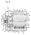
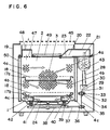
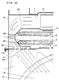
- Fig. 1 is a side sectional view of a conventional cooking appliance; Fig. 2 is a front sectional view of said appliance; Fig. 3 is a plan sectional view of said appliance; Fig. 4 is a right-hand side sectional view of a cooling appliance showing an embodiment of the present invention; Fig. 5 is a left-hand side sectional view of said appliance; Fig. 6 is a front sectional view of said appliance; Fig. 7 is a plan sectional view of said appliance, showing a flow of hot air in the vicinity of the underside of a lower stage tray; Fig. 8 is a plan sectional view of said appliance, showing a flow of hot air in the vicinity of the underside of an upper stage tray and a flow of hot air in the vicinity of the upperside of the upper stage tray; Fig. 9 is a plan sectional view of said appliance, showing a flow of hot air in the vicinity of the upperside of the lower stage tray and in the vicinity of the upper wall of the heating chamber; Fig. 10 is an enlarged plan sectional view of a portion A of Fig. 9; and Fig. 11 is an exploded perspective view of the principal portion of said appliance.
- An embodiment of the invention will now be described with reference to the drawings.
- In Figs. 4 through 11, a
main body 19 has a heating chamber 1 forcooking heating loads 18. The front opening in the heating chamber 1 is provided with adoor 16. The upper wall of the heating chamber 1 is provided with an electricpower supply port 20 connected to amagnetron 21, which is a high frequency wave generator, and awaveguide 22 for radiating high frequency waves into the heating chamber 1. The electricpower supply port 20 is covered with acover 23 of dielectric material to prevent entry of food refuse and water vapor into thewaveguide 22. Placed on the bottom wall of the heating chamber 1 is a magnetically driventurntable 24, on which arotatable tray 17 is placed. Theturntable 24 is driven by acooling fan motor 25 having amotor shaft 26 carrying thereon apulley A 27 which drives, through abelt A 28, apulley B 30 mounted on aworm gear 29 having anoutput shaft 31 carrying thereon apulley C 32 which drives apulley D 34 through abelt B 33, saidpulley D 34 having apulley E 36 mounted on apulley shaft 35, so that thepulley E 36 is driven. Thepulley E 36 drives, through abelt C 37, apulley F 38 mounted on the outer surface of the bottom wall of the heating chamber 1. When thepulley F 38 is thus rotated, amagnet A 39 mounted on the pulley F 38 is rotated. Themagnet A 39 attracts amagnet B 40 on the lower surface of theturntable 24, so that the latter, supported byroller 41, is rotated. Moreover, the bottom wall of the heating chamber 1 and ametal plate 42 by which the magnet is installed are formed of a stainless steel, aluminum or other nonmagnetic metal plate to allow passage of magnetism. - A
cooling fan 43 mounted on one end of themotor shaft 26 of thecooling fan motor 25 cools themagetron 21. The air, after being used for cooling, passes through anair guide 44, most of the air passing through an opening in the upper wall of theair guide 44 and then a space between the outer surface of the upper wall of the heating chamber 1 and the upper wall of themain body 19 and being discharged through anexhaust cover 45. Part of the air enters the heating chamber 1 throughpunching holes 46 in a side wall of the heating chamber 1 and then passes through anexhaust guide 48 connected toexhaust holes 47 in the upper wall of the heating chamber 1 and then through theexhaust cover 45 to be discharged outside. The outer surface of the upper wall of the heating chamber 1 provided with aheat insulator 49 and the outer surface of the side wall of the heating chamber 1 is provided with aheat insulating plate 50. - In Figs. 7 through 9,
suction ports 3 are provided substantially in the middle of the back of the heating chamber 1 and the right and left peripheral regions are provided with abarrier wall 51, which is associated with blow-outports 4, and there is provided acompartment 8 having apartition plate 2 having the blow-outports 4 in the form of punching holes divided into three groups (upper blow-outports 4a, middle blow-outports 4b, and lower blow-out ports 4c), acombustion chamber 5, a circulationair heating chamber 63 and a circulationfan storing chamber 7. The heating chamber 1 andcompartment 8 are separate from each other, saidcompartment 8 being attached to the back of the heating chamber 1 by scews. Thecombustion chamber 5 is positioned below thecompartment 8 and the lower portion of the peripheral wall is provided with aninlet port 9 for combustion air and the top wall is formed with acombustion gas passage 10 opening to a circulationair heating chamber 63, with twomain burners 11 and asingle pilot burner 12 installed therein. The circulationair heating chamber 63 is formed so that itspartition wall 52 surrounds thesuction pots 3 of thepartition plate 2, andsuction ports 14 are formed in opposed relation to acirculation fan 13 installed in the circulationfan storing chamber 7. The right and left side walls of the circulationfan storing chamber 7 and thepartition wall 52 extend to thepartition plate 2. The portion of thepartition wall 52 in the vicinity of thepartition plate 2 is provided with acontrol wall 53, and abypass passage 54 is defined between thecontrol wall 53 and thepartition plate 2, forming a blow-outline 15 having acontrol plate 55 for hot air in the hot air blow-out section communicating with the blow-out ports 4 (upper blow-outports 4a, middle blow-out ports 4b and lower blow-outports 4c) and the heating chamber 1. - A fan deviced 56 comprises a
circulation fan 13, acirculation fan motor 57 for driving thecirculation fan 13, a self-cooling fan 58 for cooling thecirculation fan motor 57, and a circulationfan storing chamber 7 serving as a casing, saidcirculation fan 13 being removably attached to a circulationfan motor shaft 59 by afan attaching screw 60. - In the above arrangement, the hot air flowing out of the heating chamber 1 through the
suction ports 3 formed substantially in the middle of thepartition plate 2, and the combustion gas at high temperature from themain burners 11 andpilot burner 12 passing through thecombustion gas passage 10 flow into the circulationair heating chamber 6, from which they are drawn out by thecirculation fan 13 to flow into the blow-outline 15. The two hot flows are sufficiently mixed by the combining and mixing action in this suction and blow-out process and by the stirring action of thecirculation fan 13 to provide hot air at high temperature having no uneveness in temperature. - The hot air at high temperature flows along the side walls of the circulation
fan storing chamber 7, as shown in Figs. 7 through 10, but the provision of thebarrier wall 51 in the right and left peripheral regions results in a higher pressure at thebarrier wall 51, while the portion of thepartiton wall 52 corresponding to thebarrier wall 51 is provided with abypass passage 54 communicating with the heating chamber 1. As a result, the pressure in thebypass passage 54 is lower than the pressure at thebarrier wall 51. Thus, the hot air at high temperature flows along thecontrol wall 53 forming a portion of thepartition wall 52 and is blown out substantially to the middle (with respect to the horizontal plate plane) of the heating chamber 1. - As shown in Figs. 4 and 5, the section for blowing out the hot air from the
compartment 8 into the heating chamber 1 is provided with acontrol plate 55 for the hot air,such control plates 55 being positioned above or below said blow-outports 4 or vertically placed positions, whereby an upperbarrier wall region 61 and alower barrier region 62 are defined beween theblowout ports 4 and thecontrol plate 55, and the pressures at the upper and lowerbarrier wall regions ports 4 and approximately proportional to the length of the upper and lowerbarrier wall regions barrier wall regions barrier wall region 61 is longer than the lowerbarrier wall region 62, the hot air blown out of the upper blow-outports 4a on the right-hand side is deflected downwardly and at the same time it is blown out substantially to the middle (with respect to the horizontal plane) to heat theheating load 18 placed on theupper stage tray 17, striking thedoor 16, with part of said hot air being circulated and part being sucked through thesuction ports 3. As shown in Figs. 4 and 5, since the upperbarrier wall region 61 is equal in length to the lowerbarrier wall region 62, the direction of the hot air blown out of the upper blow-outports 4a on the left side is horizontal, and as shown in Fig. 9 it is blown out substantially to the middle of the heating chamber 1, heating the upper region of the heating chamber 1 to make up forthe heat of which the upper wall of the heating chamber 1 is deprived, while heating theheating load 18 placed on theupper stage tray 17 in a well-balanced manner to prevent the heating load from being deprived of its heat, and it strikes thedoor 16 on the front surface. Part of the hot air is circulated and part is sucked through thesuction ports 3. Part flows through theexhaust ports 47 of the upper wall of the heating chamber 1 into theexhaust guide 48 and then through theexhaust cover 45 to be discharged outside. As shown in Fig. 4, since the upperbarrier wall region 61 is shorter than the lowerbarrier wall region 62, the hot air blown out of the middle blow-outports 4b on the right-hand side is deflected upwardly. At the same time, it is blown out substantially to the middle of the heating chamber 1, as shown in Fig. 8, heating the bottom of theupper stage tray 17a while striking thedoor 16, with part of the hot air being circulated and part being sucked through thesuction ports 3. - As shown in Fig. 5, since the upper
barrier wall region 61 is longer than the lowerbarrier wall region 62, the hot air blown out of the middle blow-outports 4b on the left-hand side is deflected downwardly. At the same time, as shown in Fig. 9, it is blown out substantially to the middle (with respect to the horizontal plane), heating theheating load 18 placed on thelower stage tray 17b, while striking the door on the front surface, with part of the hot air being circulated and part being sucked through thesuction ports 3. As shown in Figs. 4 and 5, since the upperbarrier wall region 61 is longer than the lowerbarrier wall region 62, the hot gas blown out of the lower blow-outports 4c on the right and left sides is deflected downwardly. At the same time, as shown in Fig. 7, it is blown out substantially to the middle of the heating chamber 1, heating the bottom of thelower stage tray 17b while making up for the heat of which the bottom surface of the heating chamber 1 is deprived, thus effecting balanced heating, and striking thedoor 16 on the front surface, with part of the hot air being circulated and part being sucked through thesuction ports 3. - Thus, according to this embodiment, since the
blowout section 63 for blowing out the hot air from thecompartment 8 into the heating chamber 1 is provided with thebarrier wall 51, the pressure at thebarrier wall 51 is high. The portion of thepartition wall 52 corresponding to thebarrier wall 51 is provided with the blow-outports 4 and thebypass passage 54 communicating with the heating chamber 1. As a result, the pressure in thebypass passage 54 is lower than the pressure at thebarrier wall 51. Thus, the hot air at high temperature flows along thecontrol wall 53 forming a portion of thebarrier wall 52 and is blown out substantially to the middle (with respect to the horizontal plane) of the heating chamber 1. Further, thesection 63 for blowing out the hot air from thecompartment 8 into the heating chamber 1 is provided with thecontrol plate 55 for the hot air,such control plates 55 being positioned above or below the blow-outports 4 or vertically spaced positions, whereby the upper and lowerbarrier wall regions ports 4 and thecontrol plate 55. The pressure at the upper and lowerbarrier wall regions ports 4 and are approximately proportional to the length of the barrier wall. As a result, by changing the length of the upper and lowerbarrier wall regions ports 4. Thus, it is possible to deflect the hot air from the higher pressure region, i.e., the longer barrier wall, to the lower pressure region, i.e., the shorter barrier wall. By changing the length of thebarrier wall 51, i.e., the position of thecontrol plate 55, the blowing direction of the hot air can be changed as desired. Thus, there is no possibility that the hot air blown out of the blow-outports 4 is concentrated to locally strongly heat theheating load 18, while it is possible to intensify the weak heating, thus ensuring balanced cooking on the upper and lower stages and of the front bottom surfaces of theheating load 18, and preventing theheating load 18 from being locally dried with the moisture of the front surface evaporated to become hard and tasteless. - The upwardly or downwardly deflected hot air from the blow-out
ports 4 gradually spreads while mixing with the hot air in the heating chamber 1, and the hot air in the vicinity of theheating load 18 has less variation in temperature; thus, the hot air which is uniform in temperature throughout heats the heating loads 18 while wrapping the latter and then flows to thesuction ports 3 formed substantially in the middle of thepartition plate 2. Further, since thetrays 17 are formed of metal, their heat conductivity is high, accelerating the uniforming of the temperature of thetrays 17 and the temperature of the atmosphere, and since the trays are rotated, cooking is possible which is free of uneven heating and local drying and the menus which have heretofore been accompanied with uneven heating have been greatly improved in the present embodiment, as shown in the following table.
- As has been described so far, according to the present invention, the blowing direction of hot air is set substantially to the middle of the heating chamber and controlled as described so that it is upward, downward or horizontal, thus avoiding local drying of the heating load and making uniform the heat distribution of the middle and periphery, and facilitating a design for balance of heat quantity in heating the front and bottom surfaces of the heating loads at the upper and lower stages, so that the heating load is heated in a well-balanced manner and cooking with less uneven heating is possible.
- The above refers to a cooking appliance equipped with a high frequency heating device, but it goes without saying that the results are the same whether it is not equipped with a high frequency heating device or it is an electric cooking appliance. While two-stage cooking taken up as an embodiment has been described, the invention is applicable equally to single-stage cooking or three-stage cooking.
- List of Reference Characters in Drawings
- 1. heating chamber
- 2. partition plate
- 3. suction ports
- 4. blow-out ports
- 4a. upper blow-out ports
- 4b. middle blow-out ports
- 4c. lower blow-out ports
- 5. combution chamber
- 6. circulation air heating chamber
- 7. circulation fan storing chamber
- 8. compartment
- 9. inlet port
- 10. combustion gas passage
- 11. main burners
- 12. pilot burner
- 13. circulation fan
- 14. suction ports
- 15. blow-out line
- 16. door
- 17. trays
- 17a. upper stage tray
- 17b. lower stage tray
- 18. heating loads
- 19. main body
- 20. electric power supply port
- 21. magnetron
- 22. waveguide
- 23. cover
- 24. turntable
- 25. cooling fan motor
- 26. motor shaft
- 27. pulley A
- 28. belt A
- 29. worm gear
- 30. pulley B
- 31. output shaft
- 32. pulley C
- 33. belt B
- 34. pulley D
- 35. pulley shaft
- 36. pulley E
- 37. belt C
- 38. pulley F
- 39. magnet A
- 40. magnet B
- 41. roller
- 42. metal plate
- 43. cooling fan
- 44. air guide
- 45. exhaust cover
- 46. punching holes
- 47. exhaust holes
- 48. exhaust guide
- 49. heat insulator
- 50. heat insulating plate
- 51. barrier wall
- 52. barrier wall
- 53. control wall
- 54. bypass passage
- 55. control plate
- 56. fan device
- 57. circulation fan motor
- 58. self-cooling fan
- 59. circulation fan motor shaft
- 60. fan attaching screw
- 61. upper barrier wall region
- 62. lower barrier wall region
- 63. blow-out section
Claims (4)
Applications Claiming Priority (4)
| Application Number | Priority Date | Filing Date | Title |
|---|---|---|---|
| JP6272782A JPS58179737A (en) | 1982-04-14 | 1982-04-14 | Heating cooker |
| JP62727/82 | 1982-04-14 | ||
| JP128785/82 | 1982-07-22 | ||
| JP12878582A JPS5918322A (en) | 1982-07-22 | 1982-07-22 | Heat-cooking utensil |
Publications (3)
| Publication Number | Publication Date |
|---|---|
| EP0105931A1 EP0105931A1 (en) | 1984-04-25 |
| EP0105931A4 EP0105931A4 (en) | 1985-12-02 |
| EP0105931B1 true EP0105931B1 (en) | 1988-07-13 |
Family
ID=26403777
Family Applications (1)
| Application Number | Title | Priority Date | Filing Date |
|---|---|---|---|
| EP83901221A Expired EP0105931B1 (en) | 1982-04-14 | 1983-04-13 | Hot air circulation type cooking device |
Country Status (6)
| Country | Link |
|---|---|
| US (1) | US4627409A (en) |
| EP (1) | EP0105931B1 (en) |
| AU (2) | AU547607B2 (en) |
| CA (1) | CA1211326A (en) |
| DE (1) | DE3377385D1 (en) |
| WO (1) | WO1983003658A1 (en) |
Families Citing this family (40)
| Publication number | Priority date | Publication date | Assignee | Title |
|---|---|---|---|---|
| US4780596A (en) * | 1986-05-15 | 1988-10-25 | Kabushiki Kaisha Toshiba | Hot-air circulation cooking oven |
| AU575743B2 (en) * | 1986-05-15 | 1988-08-04 | Kabushiki Kaisha Toshiba | Circulating air cooker |
| US4813398A (en) * | 1988-05-09 | 1989-03-21 | Hobart Corporation | Convection oven |
| US4908488A (en) * | 1988-07-22 | 1990-03-13 | Samsung Electronics Co., Ltd. | Fixing device of a heating member in a combined microwave and convection cooking apparatus |
| US4867132A (en) * | 1988-11-23 | 1989-09-19 | Garland Commercial Industries, Inc. | Gas fired convection oven with improved air delivery and heat exchange structure |
| US5107097A (en) * | 1990-11-05 | 1992-04-21 | Specialty Equipment Companies, Inc. | Forced air convection oven |
| US5569402A (en) * | 1992-06-03 | 1996-10-29 | Esec S.A. | Curing oven for magazine holding computer chip lead frames, providing flow direction control for hot gas stream |
| US5285719A (en) * | 1992-09-11 | 1994-02-15 | Gas Research Institute | Rapid frozen food thawing system |
| US5485780A (en) * | 1993-02-26 | 1996-01-23 | Food Automation Service Techniques, Inc. | Rotisserie oven |
| US5387779A (en) * | 1993-11-08 | 1995-02-07 | Suzuki; Kisaku | Rice oven with forced residual heat exhaust |
| US5533444A (en) * | 1994-01-07 | 1996-07-09 | Food And Agrosystems, Inc. | High air velocity convection oven |
| US5477036A (en) * | 1994-05-14 | 1995-12-19 | Daewoo Electronics Co., Ltd. | Microwave oven with a cooling arrangement |
| EP0695915A1 (en) * | 1994-08-06 | 1996-02-07 | Whirlpool Europe B.V. | Fan-assisted oven with improved air circulation |
| US5497760A (en) * | 1994-10-17 | 1996-03-12 | G. S. Blodgett Corporation | Convection oven with power induced back draft flow |
| US5617839A (en) * | 1996-02-26 | 1997-04-08 | Premark Feg Corporation | Rack oven |
| JP3834454B2 (en) * | 2000-04-20 | 2006-10-18 | 株式会社フジマック | Turntable drive mechanism for cooking oven |
| US6837234B2 (en) * | 2002-05-03 | 2005-01-04 | Premark Feg L.L.C. | Oven heat exchanger and floor construction |
| US6854457B2 (en) | 2003-04-15 | 2005-02-15 | Premark Feg L.L.C. | Convection oven and related cooking air flow system |
| DE20314818U1 (en) * | 2003-09-24 | 2004-06-09 | Rational Ag | Baking/cooking oven with air guide has blower with air guide having several blower apertures to even out air flows within oven esp. on different levels, fro more even cooking |
| US20050103322A1 (en) * | 2003-11-14 | 2005-05-19 | Smith Robert L. | Dual flow convection oven |
| JP3835804B2 (en) * | 2004-02-10 | 2006-10-18 | 松下電器産業株式会社 | Cooking device and cooking method |
| US7235763B2 (en) * | 2004-04-08 | 2007-06-26 | Aga Foodservice Group | Cooking appliance including combination heating system |
| CN101869125B (en) | 2004-12-14 | 2013-05-01 | 印欧第斯公司 | Impingement/ convection/ microwave oven and method |
| US7814896B2 (en) * | 2005-03-01 | 2010-10-19 | Owens Corning Intellectual Capital, Llc | Range design for surface temperature control |
| US7527051B2 (en) * | 2005-05-02 | 2009-05-05 | Premark Feg L.L.C. | Oven and associated floor construction |
| EP1913308B1 (en) * | 2005-08-02 | 2016-12-07 | Arçelik Anonim Sirketi | A cooking device |
| US20070267018A1 (en) * | 2006-05-19 | 2007-11-22 | Lang Manufacturing Company | Enhanced convection heat-treatment system and method |
| EP1992879A1 (en) | 2007-05-16 | 2008-11-19 | Electrolux Home Products Corporation N.V. | Cooking oven, especially domestic cooking oven |
| DE102007027640A1 (en) * | 2007-06-15 | 2008-12-18 | BSH Bosch und Siemens Hausgeräte GmbH | Gargerätegebläsevorrichtungseinheit |
| WO2009049081A1 (en) | 2007-10-09 | 2009-04-16 | Acp, Inc. | Air circuit for cooking appliance including combination heating system |
| ATE550608T1 (en) * | 2008-06-26 | 2012-04-15 | V Zug Ag | HOT AIR OVEN WITH DEFLECTOR PLATES |
| US9080776B2 (en) * | 2008-08-26 | 2015-07-14 | General Electric Company | Fan apparency arrangement for an appliance |
| CN102211046A (en) * | 2010-04-09 | 2011-10-12 | 鸿富锦精密工业(深圳)有限公司 | Constant temperature cabinet |
| KR101428870B1 (en) * | 2012-11-27 | 2014-08-14 | 엘지전자 주식회사 | Gas oven range |
| CN105263379A (en) * | 2013-06-04 | 2016-01-20 | 皇家飞利浦有限公司 | Air-based fryer |
| US9532561B2 (en) * | 2013-12-31 | 2017-01-03 | Harold Richard Mladek | Device for killing insects with heat |
| KR101564505B1 (en) * | 2014-04-03 | 2015-10-29 | 엘지전자 주식회사 | Cooking appliance |
| US10080262B2 (en) * | 2014-05-26 | 2018-09-18 | Sharp Kabushiki Kaisha | Cooking device |
| KR101707749B1 (en) | 2015-09-21 | 2017-02-16 | 엘지전자 주식회사 | Cooking appliance |
| KR102067271B1 (en) * | 2018-07-23 | 2020-01-16 | 엘지전자 주식회사 | Cooking appliance |
Family Cites Families (11)
| Publication number | Priority date | Publication date | Assignee | Title |
|---|---|---|---|---|
| BE545433A (en) * | 1955-02-21 | 1959-10-09 | Burger Eisenwerke Gmbh | METHOD AND DEVICE FOR THAWING AND REHEATING FOODS FROZEN TO THE HEART. |
| FR1515884A (en) * | 1966-08-02 | 1968-03-08 | Heating device by forced gas convection, forming an oven for bakery, pastry, delicatessen or the like | |
| AU470287B2 (en) * | 1971-07-16 | 1976-03-11 | Scott Brothers Limited | Improvements in and relating to heating chambers |
| US3710775A (en) * | 1971-12-13 | 1973-01-16 | Rinnai Kk | Hot air cooking oven |
| DE2557867C3 (en) * | 1975-12-22 | 1979-11-08 | Bosch-Siemens Hausgeraete Gmbh, 7000 Stuttgart | Convection oven |
| US4109636A (en) * | 1976-12-22 | 1978-08-29 | British Gas Corporation | Forced convection ovens |
| JPS579612Y2 (en) * | 1977-02-14 | 1982-02-24 | ||
| DE2754663C3 (en) * | 1977-12-08 | 1982-02-25 | Mathias 4815 Schloss Holte Mitter | Device in which paint or the like applied by means of a screen stencil. is sucked into air-permeable material |
| JPS5950890B2 (en) * | 1979-06-25 | 1984-12-11 | 株式会社東芝 | heating device |
| JPS5642028A (en) * | 1979-09-12 | 1981-04-20 | Matsushita Electric Ind Co Ltd | Heating cooker |
| US4395233A (en) * | 1981-06-22 | 1983-07-26 | G. S. Blodgett Co., Inc. | Dual flow heating apparatus |
-
1983
- 1983-04-13 AU AU14745/83A patent/AU547607B2/en not_active Ceased
- 1983-04-13 DE DE8383901221T patent/DE3377385D1/en not_active Expired
- 1983-04-13 WO PCT/JP1983/000112 patent/WO1983003658A1/en active IP Right Grant
- 1983-04-13 EP EP83901221A patent/EP0105931B1/en not_active Expired
- 1983-04-13 CA CA000425758A patent/CA1211326A/en not_active Expired
- 1983-04-13 US US06/782,607 patent/US4627409A/en not_active Expired - Fee Related
-
1985
- 1985-08-21 AU AU46521/85A patent/AU570575B2/en not_active Ceased
Also Published As
| Publication number | Publication date |
|---|---|
| CA1211326A (en) | 1986-09-16 |
| AU570575B2 (en) | 1988-03-17 |
| DE3377385D1 (en) | 1988-08-18 |
| WO1983003658A1 (en) | 1983-10-27 |
| US4627409A (en) | 1986-12-09 |
| EP0105931A4 (en) | 1985-12-02 |
| AU547607B2 (en) | 1985-10-24 |
| AU1474583A (en) | 1983-11-04 |
| AU4652185A (en) | 1985-11-28 |
| EP0105931A1 (en) | 1984-04-25 |
Similar Documents
| Publication | Publication Date | Title |
|---|---|---|
| EP0105931B1 (en) | Hot air circulation type cooking device | |
| US4743728A (en) | Dual path air circulation system for microwave ovens | |
| US4415788A (en) | Induction cartridge | |
| EP0023827B1 (en) | Cooking appliance of hot air circulating type | |
| RU2312274C2 (en) | Stove for cooking | |
| JPS6313091B2 (en) | ||
| EP0917408B1 (en) | Air circulation structure for microwave oven | |
| US6689991B2 (en) | Electronic range | |
| US8546735B2 (en) | Microwave oven | |
| US5886328A (en) | Cooking chamber cavity structure of microwave ovens | |
| JPS5918322A (en) | Heat-cooking utensil | |
| US5336867A (en) | Convection oven tapered air heating chamber | |
| JPH06103099B2 (en) | Hot air circulation cooker | |
| JPS58179737A (en) | Heating cooker | |
| KR960007560B1 (en) | Air guide for microwave oven | |
| KR960011452B1 (en) | Hot air convecting apparatus in microwave oven | |
| JP2000039153A (en) | Heating cooker | |
| EP0468640A1 (en) | High frequency heating apparatus | |
| JPH05312326A (en) | Heat cooker | |
| KR960004459Y1 (en) | Air guide apparatus for microwave oven | |
| KR100300120B1 (en) | Convection oven | |
| JPH0126964Y2 (en) | ||
| GB2230926A (en) | Microwave oven with improved cooling of the magnetron | |
| JPS58156127A (en) | Heating cooker | |
| JPH01139933A (en) | Heating and cooking appliance |
Legal Events
| Date | Code | Title | Description |
|---|---|---|---|
| PUAI | Public reference made under article 153(3) epc to a published international application that has entered the european phase |
Free format text: ORIGINAL CODE: 0009012 |
|
| 17P | Request for examination filed |
Effective date: 19831221 |
|
| AK | Designated contracting states |
Designated state(s): DE GB |
|
| 17Q | First examination report despatched |
Effective date: 19860722 |
|
| D17Q | First examination report despatched (deleted) | ||
| GRAA | (expected) grant |
Free format text: ORIGINAL CODE: 0009210 |
|
| AK | Designated contracting states |
Kind code of ref document: B1 Designated state(s): DE GB |
|
| REF | Corresponds to: |
Ref document number: 3377385 Country of ref document: DE Date of ref document: 19880818 |
|
| PLBE | No opposition filed within time limit |
Free format text: ORIGINAL CODE: 0009261 |
|
| STAA | Information on the status of an ep patent application or granted ep patent |
Free format text: STATUS: NO OPPOSITION FILED WITHIN TIME LIMIT |
|
| 26N | No opposition filed | ||
| REG | Reference to a national code |
Ref country code: GB Ref legal event code: 746 Effective date: 19951123 |
|
| PGFP | Annual fee paid to national office [announced via postgrant information from national office to epo] |
Ref country code: GB Payment date: 19970404 Year of fee payment: 15 |
|
| PGFP | Annual fee paid to national office [announced via postgrant information from national office to epo] |
Ref country code: DE Payment date: 19970418 Year of fee payment: 15 |
|
| PG25 | Lapsed in a contracting state [announced via postgrant information from national office to epo] |
Ref country code: GB Free format text: LAPSE BECAUSE OF NON-PAYMENT OF DUE FEES Effective date: 19980413 |
|
| GBPC | Gb: european patent ceased through non-payment of renewal fee |
Effective date: 19980413 |
|
| PG25 | Lapsed in a contracting state [announced via postgrant information from national office to epo] |
Ref country code: DE Free format text: LAPSE BECAUSE OF NON-PAYMENT OF DUE FEES Effective date: 19990202 |