EP0105500B1 - Scaffolding systems and connectors for use in such systems - Google Patents
Scaffolding systems and connectors for use in such systems Download PDFInfo
- Publication number
- EP0105500B1 EP0105500B1 EP83109815A EP83109815A EP0105500B1 EP 0105500 B1 EP0105500 B1 EP 0105500B1 EP 83109815 A EP83109815 A EP 83109815A EP 83109815 A EP83109815 A EP 83109815A EP 0105500 B1 EP0105500 B1 EP 0105500B1
- Authority
- EP
- European Patent Office
- Prior art keywords
- connector
- post
- wedge
- cross
- slot
- Prior art date
- Legal status (The legal status is an assumption and is not a legal conclusion. Google has not performed a legal analysis and makes no representation as to the accuracy of the status listed.)
- Expired
Links
- 210000003414 extremity Anatomy 0.000 claims abstract description 32
- 210000001364 upper extremity Anatomy 0.000 claims abstract description 10
- 210000003141 lower extremity Anatomy 0.000 claims abstract description 9
- 230000006641 stabilisation Effects 0.000 claims 2
- 238000011105 stabilization Methods 0.000 claims 2
- 238000000926 separation method Methods 0.000 claims 1
- 238000005266 casting Methods 0.000 description 5
- 230000008901 benefit Effects 0.000 description 4
- 238000010276 construction Methods 0.000 description 4
- 230000001788 irregular Effects 0.000 description 4
- 238000005304 joining Methods 0.000 description 3
- 238000003860 storage Methods 0.000 description 3
- 238000005242 forging Methods 0.000 description 2
- 238000003780 insertion Methods 0.000 description 2
- 230000037431 insertion Effects 0.000 description 2
- 238000004519 manufacturing process Methods 0.000 description 2
- 238000012986 modification Methods 0.000 description 2
- 230000004048 modification Effects 0.000 description 2
- 239000007787 solid Substances 0.000 description 2
- 238000003466 welding Methods 0.000 description 2
- 230000009471 action Effects 0.000 description 1
- 230000008878 coupling Effects 0.000 description 1
- 238000010168 coupling process Methods 0.000 description 1
- 238000005859 coupling reaction Methods 0.000 description 1
- 238000005520 cutting process Methods 0.000 description 1
- 230000000694 effects Effects 0.000 description 1
- 238000010438 heat treatment Methods 0.000 description 1
- 239000002184 metal Substances 0.000 description 1
- 238000004080 punching Methods 0.000 description 1
- 238000003908 quality control method Methods 0.000 description 1
- 238000007493 shaping process Methods 0.000 description 1
- 239000002893 slag Substances 0.000 description 1
Images



Classifications
-
- E—FIXED CONSTRUCTIONS
- E04—BUILDING
- E04G—SCAFFOLDING; FORMS; SHUTTERING; BUILDING IMPLEMENTS OR AIDS, OR THEIR USE; HANDLING BUILDING MATERIALS ON THE SITE; REPAIRING, BREAKING-UP OR OTHER WORK ON EXISTING BUILDINGS
- E04G7/00—Connections between parts of the scaffold
- E04G7/30—Scaffolding bars or members with non-detachably fixed coupling elements
- E04G7/302—Scaffolding bars or members with non-detachably fixed coupling elements for connecting crossing or intersecting bars or members
- E04G7/306—Scaffolding bars or members with non-detachably fixed coupling elements for connecting crossing or intersecting bars or members the added coupling elements are fixed at several bars or members to connect
- E04G7/307—Scaffolding bars or members with non-detachably fixed coupling elements for connecting crossing or intersecting bars or members the added coupling elements are fixed at several bars or members to connect with tying means for connecting the bars or members
-
- E—FIXED CONSTRUCTIONS
- E04—BUILDING
- E04G—SCAFFOLDING; FORMS; SHUTTERING; BUILDING IMPLEMENTS OR AIDS, OR THEIR USE; HANDLING BUILDING MATERIALS ON THE SITE; REPAIRING, BREAKING-UP OR OTHER WORK ON EXISTING BUILDINGS
- E04G7/00—Connections between parts of the scaffold
- E04G7/30—Scaffolding bars or members with non-detachably fixed coupling elements
- E04G7/32—Scaffolding bars or members with non-detachably fixed coupling elements with coupling elements using wedges
-
- Y—GENERAL TAGGING OF NEW TECHNOLOGICAL DEVELOPMENTS; GENERAL TAGGING OF CROSS-SECTIONAL TECHNOLOGIES SPANNING OVER SEVERAL SECTIONS OF THE IPC; TECHNICAL SUBJECTS COVERED BY FORMER USPC CROSS-REFERENCE ART COLLECTIONS [XRACs] AND DIGESTS
- Y10—TECHNICAL SUBJECTS COVERED BY FORMER USPC
- Y10T—TECHNICAL SUBJECTS COVERED BY FORMER US CLASSIFICATION
- Y10T403/00—Joints and connections
- Y10T403/30—Laterally related members connected by latch means, e.g., scaffold connectors
Definitions
- the present invention relates to scaffolding systems for use in construction and other related industries, and to connectors for use in such systems.
- Scaffolding systems of the post and runner type have the versatile capacity of being assembled in irregular shapes (such as encountered in petrochemical construction and in ship- building), as well as in the more conventional rectangular grid pattern.
- brackets and their respective end connectors also have serious problems, particularly when made as castings, because of the difficulty of quality control due to slag inclusions, large grain areas, hairline fractures, and other imperfections having significant potential for failure. These imperfections are very difficult to detect and appear in a significant proportion of all castings. Also of concern is the difficulty in reliably heat treating castings to achieve effective welds for joining such brackets to the upright post and such end connections to the horizontal runners. Heat treating is required for strength, because of the type of cast metal needed to assure reasonable welds. This heat treatment is not always evenly done, and the resulting imperfections are also difficult to detect.
- a universal feature for all known commercial scaffolding of this type includes the separate fabrication of the connector and the subsequent joinder thereof by welding, swaging, or the like, to the end of the horizontal cross-member.
- Figures 8 and 9 in patent No. 3,420,557 there is a "paper" disclosure of a rudimentary connector formed from the end of a cross-member. This incidental description is regarded by those skilled in the art as not involving a practical disclosure.
- the disclosed device if integrally made from reasonably light tubing (so as to be commercially acceptable), could not be safety certified.
- the connector would not give a rigid connection and would be too fragile for normal loading and even incidental handling at a construction site.
- the disclosure has been presented as an incomplete afterthought which, if practical, would have warranted a more prominent discussion. There is no teaching of how to modify this embryonic concept to a practical design. Also, the disclosure has been in the context of contrary teachings with respect to the preferred embodiments (which all require separate fabrication and attachment of the non- integral connectors to the ends of horizontal . cross-members).
- the Applicant has developed and herein discloses a practical scaffolding connector integrally formed in one, or preferably both, ends of a scaffolding cross-member. Surprisingly, this was accomplished merely by cutting and shaping the end of said cross-member without any need for heat treating or the like.
- a scaffolding connector positioned at one end of a scaffolding cross-member and suitable for engaging with a bracket affixed to a scaffolding post and for fastening to said bracket and against a convex surface of said post by a wedge inserted through an aperture in said bracket, characterised in that: said connector is integrally formed from one end of a tubular member with a longitudinally extending cross-slot in said end; in that said slot divides said connector at its free end into an upper limb and a lower limb, each limb'being formed in a non-tubular hollow thin-walled shape effective to strengthen and stiffen said limbs for supporting scaffolding loads and connection stresses; in that a pair of holes are provided with one hole formed in one limb and the other hole formed in the other limb so that said pair of holes aligns substantially perpendicularly to said slot; in that said holes are positioned and shaped to align with said aperture in said bracket when the latter is positioned in the slot of said connector with the free ends
- a scaffolding system comprising a vertical post with at least one bracket affixed thereto, characterised by a cross-member having a connector in accordance with said one aspect of the invention and by a wedge securely positioned in said pair of holes and through an aperture in said bracket thereby fastening said cross-member to said post through said connector and bracket.
- the vertical post is concentrically welded to a conventional locking ring of the type formed as an annular disc having a plurality of apertures, e.g. cutouts (typically four or eight in number) equispaced about the ring and advantageously with substantially identical maximum and minimum radii.
- cutout applies generally to holes in the brackets or locking rings of scaffolding posts which pass axially therethrough and typically are formed by casting, by punching from flat plate, or (as preferred and taught by applicant) by forging.
- the connector according to this preferred embodiment of the present invention is integrally formed in the end of a tubular horizontal cross-member.
- a horizontal cross-slot is centrally formed in the end face of the connector, thus forming two opposing notches in the latter, thus permitting it to be closely fitted over the locking ring with the end face engaging the side of the post.
- the ends of each limb are formed in a U-shape, with the open end of each facing the other.
- the resulting essentially parallel legs of the U-shaped limbs insure at least four widely spaced points of contact with the post and also stiffen said limbs (as previously indicated). This gives a solid base of contact between the end of the cross-member and the post. In fact, because the legs can have a slight lateral flex when the end of the cross-member is wedged against the post (as described below), the generally parallel legs can thus be constructed to flex into alignment with the post to give four widely spaced lines of contact, rather than mere points of contact.
- the web joining said legs be recessed.
- This advantageous recessing should be at least sufficient to conform the web to the cylindrical shape of the circular post.
- the recessing of the web be enough to insure the desired widely spaced contact between the legs and the post (without any contact of the webbing with the post).
- a hole through each of the limbs of the connector is respectively shaped and positioned so that a wedge passed through this pair of holes and through one of the aligned cutouts in the locking ring, when the latter is positioned in the cross-slot of the connector, will rigidly fasten the cross-member to the vertical post.
- This pair of holes is perpendicular to the plane of the cross-slot and when in position on the locking ring is aligned parallel to the axis of the post.
- the outside edge of the wedge When engaged, the outside edge of the wedge bears on the surface of each of the pair of holes which faces away from the post.
- the inside edge of the wedge (which is preferably inclined at approximately 7°) engages the inner surface of the cutout which faces said post.
- the bracket may have only a single aperture, it is preferred that there be at least four such apertures spaced at 90° so that a conventional rectangular scaffolding can be erected.
- the full versatility of this equipment is not realized unless there are at least eight apertures at 45° angles. These can be conveniently of identical configuration, or otherwise.
- the number of apertures can be increased even further, it has been found that sufficient versatility in varying the angle of placement can be achieved with just eight apertures, where the apertures themselves are in the form of truncated sectors which subtend a sufficient angle (e.g. 32°) to permit the horizontal cross-members to be fixed at differing angles within a given cutout (for example, an approximate 16° variation is possible with a 32° aperture given the dimensions of the preferred embodiment shown in the drawings).
- Figure 1 shows the type of versatility that post and runner scaffolding systems have with regard to irregular shapes such as the illustrated storage tank 20.
- the scaffolding assembly 22 is made up of vertical support posts 24 joined to cross-members which can be either runners 26 or diagonals 28.
- this scaffolding assembly 22 has been formed into a free-standing stair tower 30 with support units 32 having pairs of longitudinal horizontals 26 of different lengths, thus enabling the scaffolding to form a polygonal support structure around the circular tank 20.
- the post 24 has a plurality of brackets 34 (illustrated in the form of locking rings) advantageously equispaced therealong.
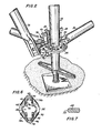
- a connector 36 Integrally formed in the end of the horizontal 26 is a connector 36 (see figures 3 to 6 in particular).
- a horizontal cross-slot 38 is cut longitudinally into the free end of the integral connector 36, thus forming an upper limb 40 and a lower limb 42, preferably of equal size.
- Holes 44 and 46 are formed in the respective upper and lower limbs 40 and 42 to accommodate a locking wedge 48.
- the straight outer edge 50 of the wedge 48 is advantageously of a curved shape.
- the holes 44 and 46 define corresponding circular surfaces 52 and 54 against which the wedge 48 bears when forcing the free end 56 of the connector 36 against the post 24 (see figure 3).
- the inner edge 57 of the locking wedge functions as the opposing wedging surface which bears on the inner bearing surface 58 of one of the cutouts 60 in the locking ring 34.
- the bearing surfaces 52 and 54 are equidistant from the free end 56 of the connector.
- the hole 44 is small enough to prevent the head of the wedge 48 from passing through, but is longitudinally large enough not to engage the wedge surface 57 when in the locked position.
- the sides of the hole 44 are sufficiently close together to engage the rivet 62 and thus prevent the complete disengagement of the wedge 48 from the connector 36.
- the hole 46 in the bottom limb 42 is sufficiently wide to permit the wedge tip 61 with the retaining rivet 62 to pass through the hole 46, thus enabling the wedge 48 to be retracted away from the lower limb and to lie wholly within or along the length of the upper limb (see the dash-dot outline of the wedge 48 in figure 3).
- the particular J-shape of the wedge 48 ensures that the slot 38 is clear of obstruction by the wedge 48 during assembly of the connector onto the locking ring 34. It also permits the length of the wedge 48 to lie along the length of the horizontal 26 and be substantially out of harm's way during storage and assembly operations.
- FIG 11 Illustrated in figure 11 are a modified wedge 48a and connector 36a which are designed to enable the horizontal 26a to be placed on the locking ring 34 and cause the locking wedge 48a to drop into place through a cutout 60, usually without the necessity for actually handling the wedge 48a. In normal use this has been found to operate automatically at least 70% of the time. By careful proper handling this percentage can be significantly increased.
- This modified locking wedge 48a has a notch 64 in the lower end of the inner edge 57a. This is positioned so that the greater portion of the wedge 48a protrudes from the upper hole 44a and lies back towards the length of the connector 26a. In this weighted position, the lower tip 61 a of the wedge 48a (bearing the rivet 62) protrudes slightly into the cross-slot 38a. There is sufficient clearance between the chamfered lead-in to the slots 38a and the tip 61a of the wedge to permit the outer portion of the locking ring 34 and a cutout 60 to pass beneath the tip 61 a.
- the length of the horizontal 26a is then aligned with the plane of the locking ring 34 whereby the tip 61 a protrudes slightly into the cutout 60.
- the wedge 48a is caused to tip up the wedge 48a and upon full insertion to drop down through the cutout 60 and through the hole 46a in the lower limb 42a.
- the wedging surfaces 50 and 57 are preferably angled to each other at about 7°.
- the upper portion of the bearing surface 58 of the locking ring 34 is preferably inclined at about 5° to the vertical, thus giving both a good bearing surface and also enabling the locking ring to be forged rather than cast, resulting in a greatly superior structure.
- each- of the cutouts 60 should have the bearing surface 58 at a common maximum radius, so that the connector 36 can be effectively mounted in any one of the cutouts and be functional with respect thereto.
- the inner circular arc defining the opposite face of each of the cutouts 60 is prefer: ably at the same minimum radius, or at least of a sufficiently small radius to prevent the bearing surface 50 of the wedge 48 from engaging that surface when in the operative position.
- a particularly advantageous feature of applicant's unique invention is in forming an end of a tubular horizontal 26 into a connector 36 whose end face 56, being divided by the slot 38, results in two facing U-shapes. These can result from the connector being initially in the shape of a box channel. More typically, the horizontal 26 is made from circular tubing of essentially the same size as the vertical post 24. Applicant thus derives these U-shaped end faces from the circular tubing by flattening the sides of the tubular circular horizontal 26, preferably into straight sided cheeks 68 and 70. This has the advantage of stiffening the limbs and also of permitting eight or more connectors to be simultaneously mounted on the locking ring 34 and to abut their free ends against the post 24.
- the webs 72 and 74 are preferably formed in a V-shape with the legs of the V perpendicular to the adjacent cheek 68 or 70 of the connector 36. With the cheeks 68 and 70 substantially radially aligned relative to the central axis of the post when engaged as shown in figure 3, the faces of the legs 76a & b and 78a & b are seated flat against the surface of the post 24.
- the connector 36 at the open end of the cross-slot 38 has chamfered faces 80 both to serve as a lead-in to the slot 38 for the locking ring 34 and also to provide clearance for the welding seam 82 joining the ring 34 to the post 24.
- Figures 2 and 10A & B illustrate how the connector 36, integrally formed from circular tubing, can be employed in making diagonal bracing 28.
- the connector 36 is cut at a 45° angle to its length and welded to an elliptical plate 84.
- the end of the diagonal tubing 28 is flattened and riveted to the plate 84.
- the plate 84 is enabled to rotate relative to the diagonal 28 and thus permit the diagonal to serve as either a right or left-hand diagonal.
- Figure 12 illustrates how the connector of the invention can be adapted for use with a sidewall bracket 86, optionally joined to a guard rail post by a riveted coupling pin 90.
Landscapes
- Engineering & Computer Science (AREA)
- Architecture (AREA)
- Mechanical Engineering (AREA)
- Civil Engineering (AREA)
- Structural Engineering (AREA)
- Mutual Connection Of Rods And Tubes (AREA)
- Tents Or Canopies (AREA)
- Electric Cable Installation (AREA)
- Spinning Or Twisting Of Yarns (AREA)
- Clamps And Clips (AREA)
- Ladders (AREA)
- Farming Of Fish And Shellfish (AREA)
- Earth Drilling (AREA)
Abstract
Description
- The present invention relates to scaffolding systems for use in construction and other related industries, and to connectors for use in such systems. Scaffolding systems of the post and runner type have the versatile capacity of being assembled in irregular shapes (such as encountered in petrochemical construction and in ship- building), as well as in the more conventional rectangular grid pattern.
- Most conventional scaffolding is made from welded end frames having two vertical legs with welded cross pieces, said frames being assembled as a basic unit in pairs with removable cross bracing (see for example US Patent No. 3,109,405). This conventional scaffolding has the advantage of rigidity and quick. assembly-disassembly (which derives from the use of the welded end frames). Conventional post and runner scaffolding are joined by the use of threaded clamps. These are labour intensive and time consuming to assemble and require more costly skilled labour to erect. There has been a continuing attempt over the years to improve the usefulness of the single post and runner type of scaffolding to increase the speed and ease of assembly, to improve rigidity, and at the same time to retain the versatility relative to irregular shapes.
- US patents illustrating such earlier work include No. 3,179,212, issued April 20, 1965, to P.E. Gostling; No. 3,420,557, issued January 7, 1969, to L.W. Francis, et al; No. 3,992,118, issued November 16, 1976, to E.H.G. Slegers; No. 4,044,523, issued August 30, 1977, to E. Layher; and No. 4,273,463, issued June 16, 1981, to G. Dobersch. British patent No.1,278,243 published June 21, 1972 to Elson is also illustrative.
- Most of these commonly teach the joinder of a runner (or other horizontal or diagonal cross-member) to a vertical upright circular post by means of a wedge fastening a connector at the end of the horizontal cross-member to the vertical post by interconnection with a bracket affixed thereto. The only exception to this is the Slegers patent which uses the wedging action of a locking cup, rather than a separate wedge. The brackets . used in the earlier patents were U-shaped loops or straps (called "sockets") whose ends were welded to the post. These loops are subject to being pulled off in daily use. This problem has been avoided in the ring or cup brackets utilized in the Elson, Layher or Dobersch patents. However, these brackets and their respective end connectors also have serious problems, particularly when made as castings, because of the difficulty of quality control due to slag inclusions, large grain areas, hairline fractures, and other imperfections having significant potential for failure. These imperfections are very difficult to detect and appear in a significant proportion of all castings. Also of concern is the difficulty in reliably heat treating castings to achieve effective welds for joining such brackets to the upright post and such end connections to the horizontal runners. Heat treating is required for strength, because of the type of cast metal needed to assure reasonable welds. This heat treatment is not always evenly done, and the resulting imperfections are also difficult to detect.
- A universal feature for all known commercial scaffolding of this type (and also of the preferred embodiments taught by the aforementioned patents) includes the separate fabrication of the connector and the subsequent joinder thereof by welding, swaging, or the like, to the end of the horizontal cross-member. In a brief description of Figures 8 and 9 in patent No. 3,420,557 (column 4, lines 51-56 and column 7, lines 12-21), there is a "paper" disclosure of a rudimentary connector formed from the end of a cross-member. This incidental description is regarded by those skilled in the art as not involving a practical disclosure. The disclosed device, if integrally made from reasonably light tubing (so as to be commercially acceptable), could not be safety certified. For example, it is thought that the connector would not give a rigid connection and would be too fragile for normal loading and even incidental handling at a construction site. The disclosure has been presented as an incomplete afterthought which, if practical, would have warranted a more prominent discussion. There is no teaching of how to modify this embryonic concept to a practical design. Also, the disclosure has been in the context of contrary teachings with respect to the preferred embodiments (which all require separate fabrication and attachment of the non- integral connectors to the ends of horizontal . cross-members).
- It is thus an object of this invention to develop a scaffolding connector and system which is simple of construction, is easy and reliable to use, has significant safety advantages over all potential and commercially available prior art, and makes a rigid joint when assembled.
- The Applicant has developed and herein discloses a practical scaffolding connector integrally formed in one, or preferably both, ends of a scaffolding cross-member. Surprisingly, this was accomplished merely by cutting and shaping the end of said cross-member without any need for heat treating or the like.
- According to one aspect of the invention, there is provided a scaffolding connector positioned at one end of a scaffolding cross-member and suitable for engaging with a bracket affixed to a scaffolding post and for fastening to said bracket and against a convex surface of said post by a wedge inserted through an aperture in said bracket, characterised in that: said connector is integrally formed from one end of a tubular member with a longitudinally extending cross-slot in said end; in that said slot divides said connector at its free end into an upper limb and a lower limb, each limb'being formed in a non-tubular hollow thin-walled shape effective to strengthen and stiffen said limbs for supporting scaffolding loads and connection stresses; in that a pair of holes are provided with one hole formed in one limb and the other hole formed in the other limb so that said pair of holes aligns substantially perpendicularly to said slot; in that said holes are positioned and shaped to align with said aperture in said bracket when the latter is positioned in the slot of said connector with the free ends of said limbs abutting said post and in that the respective surfaces which define said holes and face away from said one end of said tubular member are suitable to bear on said wedge when positioned therein and said holes are suitable to accommodate said wedge in a position such that the latter is free to bear opposingly against a surface of said aperture facing said post.
- According to another aspect of the invention, there is provided a scaffolding system comprising a vertical post with at least one bracket affixed thereto, characterised by a cross-member having a connector in accordance with said one aspect of the invention and by a wedge securely positioned in said pair of holes and through an aperture in said bracket thereby fastening said cross-member to said post through said connector and bracket.
- In the preferred embodiment hereafter described, the vertical post is concentrically welded to a conventional locking ring of the type formed as an annular disc having a plurality of apertures, e.g. cutouts (typically four or eight in number) equispaced about the ring and advantageously with substantially identical maximum and minimum radii. The term "cutout" applies generally to holes in the brackets or locking rings of scaffolding posts which pass axially therethrough and typically are formed by casting, by punching from flat plate, or (as preferred and taught by applicant) by forging.
- The connector according to this preferred embodiment of the present invention is integrally formed in the end of a tubular horizontal cross-member. A horizontal cross-slot is centrally formed in the end face of the connector, thus forming two opposing notches in the latter, thus permitting it to be closely fitted over the locking ring with the end face engaging the side of the post. In order to give strength to the upper and lower limbs of the connector created by the cross-slot and also to give a rigid joint between the end face of the connector and the post, the ends of each limb are formed in a U-shape, with the open end of each facing the other. The resulting essentially parallel legs of the U-shaped limbs insure at least four widely spaced points of contact with the post and also stiffen said limbs (as previously indicated). This gives a solid base of contact between the end of the cross-member and the post. In fact, because the legs can have a slight lateral flex when the end of the cross-member is wedged against the post (as described below), the generally parallel legs can thus be constructed to flex into alignment with the post to give four widely spaced lines of contact, rather than mere points of contact.
- In order for the end face of the connector to make the aforementioned preferred four points of contact in this preferred embodiment or four lines of contact, it is necessary that the web joining said legs be recessed. This advantageous recessing should be at least sufficient to conform the web to the cylindrical shape of the circular post. However, since it would be costly to maintain exact tolerances for close interfitting, it is preferred that the recessing of the web be enough to insure the desired widely spaced contact between the legs and the post (without any contact of the webbing with the post).
- A hole through each of the limbs of the connector is respectively shaped and positioned so that a wedge passed through this pair of holes and through one of the aligned cutouts in the locking ring, when the latter is positioned in the cross-slot of the connector, will rigidly fasten the cross-member to the vertical post. This pair of holes is perpendicular to the plane of the cross-slot and when in position on the locking ring is aligned parallel to the axis of the post.
- When engaged, the outside edge of the wedge bears on the surface of each of the pair of holes which faces away from the post. The inside edge of the wedge (which is preferably inclined at approximately 7°) engages the inner surface of the cutout which faces said post. Thus, as the wedge is driven into place, the wedge forcefully presses the end face of the connector against the post to form a rigid connection.
- Although in its broadest aspects, the bracket may have only a single aperture, it is preferred that there be at least four such apertures spaced at 90° so that a conventional rectangular scaffolding can be erected. However, the full versatility of this equipment is not realized unless there are at least eight apertures at 45° angles. These can be conveniently of identical configuration, or otherwise. Although the number of apertures can be increased even further, it has been found that sufficient versatility in varying the angle of placement can be achieved with just eight apertures, where the apertures themselves are in the form of truncated sectors which subtend a sufficient angle (e.g. 32°) to permit the horizontal cross-members to be fixed at differing angles within a given cutout (for example, an approximate 16° variation is possible with a 32° aperture given the dimensions of the preferred embodiment shown in the drawings).
- In this specification and in the accompanying drawings are shown and described preferred embodiments of the invention and various alternatives and modifications thereof are suggested, but it is to be understood that these are not intended to be exhaustive and that many other changes and modifications can be made within the scope of the invention. The suggestions herein are selected and included for purposes of illustration in order that others skilled in the art will more fully understand the invention and the principles thereof and will thus be enabled to modify it in a variety of forms, each as may be best suited to the conditions of a particular use.
- For a better understanding of the invention and to show how the same may be carried into effect, reference will now be made, by way of example, to the accompanying drawings, in which:
- Figure 1 is a perspective view showing a scaffolding system according to the present invention as employed with respect to an irregular shape such as a storage tank;
- Figure 2 is a closeup perspective view showing the details of a preferred embodiment of part of the scaffolding system according to the present invention, including a conventional post and locking ring with a conventional jack screw, with unique horizontal cross-members having connectors integrally formed in their ends, with each connector carrying its respective locking wedge;
- Figure 3 is a side elevation, including a vertical cross section through the locking ring of the structure shown in Figure 2;
- Figures 4 and 5 are respectively top and bottom views of the connector shown in Figures 2 and 3;
- Figure 6 is an end view of the connector shown in Figures 4 and 5;
- Figure 7 is a horizontal cross section taken along lines 7-7 in Figure 3 of the locking wedge;
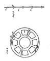
- Figure 8 is a plan view of a preferred embodiment of the locking ring shown in Figures 2 and 3;
- Figure 9 is a side elevation of a vertical scaffolding post showing the positioning of the locking rings welded thereon;
- Figure 10A is a plan view of a diagonal cross-member having the unique connector according to the present invention, pivotally connected at a 45° angle to the flattened end of the diagonal cross-member;
- Figure 10B is a side elevation of the structure shown in Figure 10A;
- Figure 11 is a side elevation showing a second embodiment of the present invention involving a modified wedge and connector assembly which is semiautomatic in operation; and
- Figure 12 is a side elevation of a sidewall bracket assembly (and of an interconnectable guard rail post) incorporating the unique connector of the present invention.
- Figure 1 shows the type of versatility that post and runner scaffolding systems have with regard to irregular shapes such as the illustrated
storage tank 20. Thescaffolding assembly 22 is made up of vertical support posts 24 joined to cross-members which can be eitherrunners 26 ordiagonals 28. - As illustrated in figure 1, this
scaffolding assembly 22 has been formed into a free-standingstair tower 30 withsupport units 32 having pairs oflongitudinal horizontals 26 of different lengths, thus enabling the scaffolding to form a polygonal support structure around thecircular tank 20. - As shown in figures 2 and 9, the
post 24 has a plurality of brackets 34 (illustrated in the form of locking rings) advantageously equispaced therealong. - Integrally formed in the end of the horizontal 26 is a connector 36 (see figures 3 to 6 in particular). A
horizontal cross-slot 38 is cut longitudinally into the free end of theintegral connector 36, thus forming anupper limb 40 and alower limb 42, preferably of equal size.Holes lower limbs wedge 48. The straightouter edge 50 of thewedge 48 is advantageously of a curved shape. Theholes circular surfaces 52 and 54 against which thewedge 48 bears when forcing thefree end 56 of theconnector 36 against the post 24 (see figure 3). Because there are no sharp angles in the preferredcircular surfaces 52 and 54, the wedging forces from the correspondingly-shapedcylindrical wedge face 50 are more evenly spread and do not have an angled weak point to act on (as would be the case if theholes - The
inner edge 57 of the locking wedge functions as the opposing wedging surface which bears on theinner bearing surface 58 of one of thecutouts 60 in the lockingring 34. - In the preferred embodiment, the bearing surfaces 52 and 54 are equidistant from the
free end 56 of the connector. Thehole 44 is small enough to prevent the head of thewedge 48 from passing through, but is longitudinally large enough not to engage thewedge surface 57 when in the locked position. The sides of thehole 44 are sufficiently close together to engage therivet 62 and thus prevent the complete disengagement of thewedge 48 from theconnector 36. In contrast, thehole 46 in thebottom limb 42 is sufficiently wide to permit thewedge tip 61 with the retainingrivet 62 to pass through thehole 46, thus enabling thewedge 48 to be retracted away from the lower limb and to lie wholly within or along the length of the upper limb (see the dash-dot outline of thewedge 48 in figure 3). The particular J-shape of thewedge 48 ensures that theslot 38 is clear of obstruction by thewedge 48 during assembly of the connector onto the lockingring 34. It also permits the length of thewedge 48 to lie along the length of the horizontal 26 and be substantially out of harm's way during storage and assembly operations. - Illustrated in figure 11 are a modified
wedge 48a andconnector 36a which are designed to enable the horizontal 26a to be placed on the lockingring 34 and cause the lockingwedge 48a to drop into place through acutout 60, usually without the necessity for actually handling thewedge 48a. In normal use this has been found to operate automatically at least 70% of the time. By careful proper handling this percentage can be significantly increased. - This modified locking
wedge 48a has anotch 64 in the lower end of theinner edge 57a. This is positioned so that the greater portion of thewedge 48a protrudes from the upper hole 44a and lies back towards the length of theconnector 26a. In this weighted position, the lower tip 61 a of thewedge 48a (bearing the rivet 62) protrudes slightly into the cross-slot 38a. There is sufficient clearance between the chamfered lead-in to the slots 38a and the tip 61a of the wedge to permit the outer portion of the lockingring 34 and acutout 60 to pass beneath the tip 61 a. The length of the horizontal 26a is then aligned with the plane of the lockingring 34 whereby the tip 61 a protrudes slightly into thecutout 60. Thus on further insertion of the lockingring 34 into the slot 38a, thewedge 48a is caused to tip up thewedge 48a and upon full insertion to drop down through thecutout 60 and through the hole 46a in thelower limb 42a. - The wedging surfaces 50 and 57 are preferably angled to each other at about 7°. The upper portion of the bearing
surface 58 of the lockingring 34 is preferably inclined at about 5° to the vertical, thus giving both a good bearing surface and also enabling the locking ring to be forged rather than cast, resulting in a greatly superior structure. By forging thering 34, the problems of casting fractures are avoided. - Referring to figure 8, it will be appreciated that each- of the
cutouts 60 should have the bearingsurface 58 at a common maximum radius, so that theconnector 36 can be effectively mounted in any one of the cutouts and be functional with respect thereto. The inner circular arc defining the opposite face of each of thecutouts 60 is prefer: ably at the same minimum radius, or at least of a sufficiently small radius to prevent thebearing surface 50 of thewedge 48 from engaging that surface when in the operative position. - Referring to figure 6, a particularly advantageous feature of applicant's unique invention is in forming an end of a tubular horizontal 26 into a
connector 36 whoseend face 56, being divided by theslot 38, results in two facing U-shapes. These can result from the connector being initially in the shape of a box channel. More typically, the horizontal 26 is made from circular tubing of essentially the same size as thevertical post 24. Applicant thus derives these U-shaped end faces from the circular tubing by flattening the sides of the tubular circular horizontal 26, preferably into straightsided cheeks ring 34 and to abut their free ends against thepost 24. By narrowing the tubing transversely, it is also simultaneously lengthened vertically. This has the advantage of more widely separating theweb portion 72 and 74 of these two respective U-shaped end faces. The respective legs 76a & b and 78a & b are thus adequately widely spaced transversely and advantageously more widely spaced vertically so as to give an unusually solid base of contact by theend face 56 against the side of thepost 24. These parallel legs 76a & b and 78a & b are of a length sufficient effectively to stiffen the relatively thin-walled limbs webs 72 and 74 are preferably formed in a V-shape with the legs of the V perpendicular to theadjacent cheek connector 36. With thecheeks post 24. - The
connector 36 at the open end of the cross-slot 38 has chamfered faces 80 both to serve as a lead-in to theslot 38 for the lockingring 34 and also to provide clearance for thewelding seam 82 joining thering 34 to thepost 24. - Figures 2 and 10A & B illustrate how the
connector 36, integrally formed from circular tubing, can be employed in making diagonal bracing 28. As illustrated, theconnector 36 is cut at a 45° angle to its length and welded to anelliptical plate 84. The end of thediagonal tubing 28 is flattened and riveted to theplate 84. By riveting, theplate 84 is enabled to rotate relative to the diagonal 28 and thus permit the diagonal to serve as either a right or left-hand diagonal. - Figure 12 illustrates how the connector of the invention can be adapted for use with a
sidewall bracket 86, optionally joined to a guard rail post by a rivetedcoupling pin 90.
Claims (20)
Priority Applications (1)
| Application Number | Priority Date | Filing Date | Title |
|---|---|---|---|
| AT83109815T ATE39528T1 (en) | 1982-09-30 | 1983-09-30 | SCAFFOLDING AND CONNECTING MEANS FOR SUCH SCAFFOLDING. |
Applications Claiming Priority (2)
| Application Number | Priority Date | Filing Date | Title |
|---|---|---|---|
| US06/431,115 US4493578A (en) | 1982-09-30 | 1982-09-30 | Scaffolding connector and system |
| US431115 | 1982-09-30 |
Publications (2)
| Publication Number | Publication Date |
|---|---|
| EP0105500A1 EP0105500A1 (en) | 1984-04-18 |
| EP0105500B1 true EP0105500B1 (en) | 1988-12-28 |
Family
ID=23710529
Family Applications (1)
| Application Number | Title | Priority Date | Filing Date |
|---|---|---|---|
| EP83109815A Expired EP0105500B1 (en) | 1982-09-30 | 1983-09-30 | Scaffolding systems and connectors for use in such systems |
Country Status (8)
| Country | Link |
|---|---|
| US (1) | US4493578A (en) |
| EP (1) | EP0105500B1 (en) |
| JP (1) | JPS5991263A (en) |
| AT (1) | ATE39528T1 (en) |
| AU (1) | AU557251B2 (en) |
| CA (1) | CA1270020A (en) |
| DE (1) | DE3378775D1 (en) |
| MX (1) | MX156986A (en) |
Cited By (1)
| Publication number | Priority date | Publication date | Assignee | Title |
|---|---|---|---|---|
| DE102017007131A1 (en) * | 2017-07-31 | 2019-01-31 | Redima Ag | Steel Pipe Support and Steel Pipe Support Assembly |
Families Citing this family (40)
| Publication number | Priority date | Publication date | Assignee | Title |
|---|---|---|---|---|
| GB2133106A (en) * | 1982-12-24 | 1984-07-18 | Wah Wong | Scaffold joint |
| CA1229113A (en) * | 1983-10-26 | 1987-11-10 | Neil W. Woods | Scaffolding and locking discs therefor |
| DE3407425A1 (en) * | 1984-02-29 | 1985-09-05 | Ulrich 7129 Güglingen Layher | METAL PIPE FRAME |
| US4671382A (en) * | 1986-07-21 | 1987-06-09 | Harsco Corporation | Scaffolding system for sloped surfaces |
| US4840513A (en) * | 1986-11-05 | 1989-06-20 | Hackett Steven B | Scaffolding connector apparatus |
| DE3702057A1 (en) * | 1987-01-24 | 1988-08-04 | Langer Ruth Geb Layher | SCAFFOLDED WITH CONNECTING DEVICES |
| JPH0531158Y2 (en) * | 1987-10-19 | 1993-08-10 | ||
| DE3909809A1 (en) * | 1989-03-24 | 1990-09-27 | Langer Ruth Geb Layher | PERFORMANCE DISC FOR CONNECTING DEVICES FOR SCAFFOLDING ELEMENTS |
| JPH0751558Y2 (en) * | 1990-10-30 | 1995-11-22 | 株式会社本宏製作所 | Horizontal pipe erection equipment for pipe scaffolding |
| DE69214151D1 (en) * | 1991-07-12 | 1996-10-31 | Ronald Lubinski | ALUMINUM SCAFFOLDING |
| JPH07111094B2 (en) * | 1991-12-27 | 1995-11-29 | 小野 辰雄 | Prop device |
| ES2062945B1 (en) * | 1993-03-22 | 1998-11-01 | Ubinana Felix Jose Luis | IMPROVEMENTS IN THE ANCHOR KNOTS AND JOINT OF THE BARS OF REMOVABLE METAL STRUCTURES. |
| ES2068136B1 (en) * | 1993-05-04 | 1998-01-16 | Ulma S Coop | PERFECTED MULTIDIRECTIONAL SCAFFOLD. |
| CA2111724A1 (en) * | 1993-12-17 | 1995-06-18 | Raymond Wayne Gillard | Scaffold system |
| US5579866A (en) * | 1994-07-08 | 1996-12-03 | Sky Climber, Inc. | Suspended access platform |
| NO179877C (en) * | 1994-08-22 | 1997-01-08 | Alustar As | Device for diagonal rod attachment for scaffolding purposes |
| FR2727454A1 (en) * | 1994-11-28 | 1996-05-31 | Peyre Philippe | Scaffolding collar for building construction |
| FR2738859B1 (en) * | 1995-09-14 | 1998-01-16 | Deko | CLAMPS FOR ASSEMBLING FORMWORK PANELS |
| CA2201535C (en) | 1997-04-02 | 2006-09-19 | Aluma Systems Corp. | Scaffolding connector |
| DE19806094A1 (en) * | 1998-02-14 | 1999-08-19 | Layher W Vermogensverw Gmbh | Arrangement of structural elements of a spatial structure |
| US6481697B1 (en) * | 1999-11-10 | 2002-11-19 | Alexander Brown | Modular railing system for construction sites |
| ITTO20031003A1 (en) * | 2003-12-12 | 2005-06-13 | Fracasso Metalmeccanica | CROSSBEAM FOR PREFABRICATED SCAFFOLDING WITH QUICK ASSEMBLY AND ITS MANUFACTURING METHOD. |
| US20060039746A1 (en) * | 2004-08-11 | 2006-02-23 | Stringer Matthew D | Connecting device for scaffolding |
| DE102008006911A1 (en) * | 2008-01-24 | 2009-07-30 | Wilhelm Layher Verwaltungs-Gmbh | For the construction of a frame support, a support frame and / or a shoring tower certain vertical frame |
| SG155815A1 (en) * | 2008-03-31 | 2009-10-29 | Asia Scaffolding Pte Ltd | A connector claw |
| US8403157B2 (en) * | 2009-12-17 | 2013-03-26 | Crystal Spring Colony Farms Ltd | Storing rack for core sample boxes |
| US8393439B2 (en) * | 2010-01-26 | 2013-03-12 | Steve Howard Thacker | Scaffold system and method |
| US8656853B2 (en) * | 2010-09-27 | 2014-02-25 | Seamagine Hydrospace Corporation | Sealable dome assembly |
| US9835188B2 (en) * | 2013-03-14 | 2017-12-05 | Titan Formwork Systems Llc | Universal wedge clamp |
| US9574357B2 (en) | 2013-05-20 | 2017-02-21 | Apache Industrial Services, Inc. | Scaffold bracket |
| US9765537B2 (en) * | 2013-09-10 | 2017-09-19 | 9020-4983 Quebec Inc. | Vertical support member for a suspended scaffold assembly, kit for mounting a suspended scaffold assembly, suspended scaffold assembly and method for mounting the same |
| SE538860C2 (en) * | 2015-05-21 | 2017-01-10 | Mon Zon Dev Ab | Flexible fastening unit for a beam |
| GB2539695B (en) * | 2015-06-25 | 2019-12-18 | Ford Global Tech Llc | A bush and clamp assembly |
| DK3260395T3 (en) * | 2016-11-09 | 2020-06-02 | Interroll Holding Ag | MOUNTING DEVICE AND CARTON FLOW |
| CN110226014B (en) * | 2017-01-27 | 2020-06-16 | 日商日建租赁工业株式会社 | Connecting piece for temporary scaffold |
| DE102017211288A1 (en) * | 2017-07-03 | 2019-01-03 | Peri Gmbh | Scaffolding element with a connection between components by means of a molding and method for producing the scaffold element |
| DE102017216892A1 (en) | 2017-09-25 | 2019-03-28 | Peri Gmbh | Scaffolding element for connection to a disk-shaped connection plate and scaffolding part with such a scaffolding element |
| CN110259082B (en) * | 2019-06-06 | 2021-04-27 | 江苏建宇建设集团有限公司 | Electric bridge type scaffold |
| US12046795B2 (en) * | 2021-03-24 | 2024-07-23 | Commscope Technologies Llc | Telecommunications mounting frames and methods of making same |
| NL2033736B1 (en) * | 2022-12-16 | 2024-06-20 | Scafom Holding B V | Coupling assembly, beam assembly for a scaffold, combination, scaffolding system, and methods |
Family Cites Families (10)
| Publication number | Priority date | Publication date | Assignee | Title |
|---|---|---|---|---|
| GB1180562A (en) * | 1966-04-29 | 1970-02-04 | Kwikform Ltd | Improvements in or relating to Builders Scaffolding |
| GB1278243A (en) * | 1968-09-24 | 1972-06-21 | Alfred Victor Elson | Mounting arrangements for scaffolding |
| GB1386238A (en) * | 1971-05-28 | 1975-03-05 | Kwikform Ltd | Builders scaffolding |
| NL175840B (en) * | 1973-10-10 | 1984-08-01 | Sgb Group Plc | CONNECTING CONSTRUCTION FOR APPLICATION IN A TUBULAR SCAFFOLD OR RACK. |
| DE2449124C3 (en) * | 1974-10-16 | 1980-01-03 | Eberhard 7129 Gueglingen Layher | Connection device for scaffolding elements |
| DE2822676C2 (en) * | 1978-05-24 | 1982-08-19 | Eberhard 7129 Güglingen Layher | Connection device for scaffolding elements |
| US4273463A (en) * | 1979-10-03 | 1981-06-16 | Gerhard Dobersch | Steel tube scaffold |
| GB2066341B (en) * | 1979-12-21 | 1983-06-02 | Press Components Co Ltd | Scaffolding brace |
| GB2090640A (en) * | 1981-01-02 | 1982-07-14 | Dolan Henry Gabriel | Scaffolding joints |
| DE8112653U1 (en) * | 1981-04-29 | 1981-11-05 | Layher, Eberhard, 7129 Güglingen | "FRAME ELEMENT" |
-
1982
- 1982-09-30 US US06/431,115 patent/US4493578A/en not_active Expired - Lifetime
-
1983
- 1983-09-26 AU AU19557/83A patent/AU557251B2/en not_active Ceased
- 1983-09-28 MX MX198900A patent/MX156986A/en unknown
- 1983-09-29 CA CA000438008A patent/CA1270020A/en not_active Expired - Lifetime
- 1983-09-30 DE DE8383109815T patent/DE3378775D1/en not_active Expired
- 1983-09-30 AT AT83109815T patent/ATE39528T1/en not_active IP Right Cessation
- 1983-09-30 EP EP83109815A patent/EP0105500B1/en not_active Expired
- 1983-09-30 JP JP58182909A patent/JPS5991263A/en active Pending
Cited By (1)
| Publication number | Priority date | Publication date | Assignee | Title |
|---|---|---|---|---|
| DE102017007131A1 (en) * | 2017-07-31 | 2019-01-31 | Redima Ag | Steel Pipe Support and Steel Pipe Support Assembly |
Also Published As
| Publication number | Publication date |
|---|---|
| US4493578A (en) | 1985-01-15 |
| AU557251B2 (en) | 1986-12-11 |
| AU1955783A (en) | 1984-04-05 |
| DE3378775D1 (en) | 1989-02-02 |
| MX156986A (en) | 1988-10-18 |
| ATE39528T1 (en) | 1989-01-15 |
| CA1270020A (en) | 1990-06-05 |
| EP0105500A1 (en) | 1984-04-18 |
| JPS5991263A (en) | 1984-05-25 |
Similar Documents
| Publication | Publication Date | Title |
|---|---|---|
| US4493578A (en) | Scaffolding connector and system | |
| FI93136B (en) | Connection head for stand | |
| US4445307A (en) | Scaffold joint for a scaffold structure | |
| US5961240A (en) | Scaffolding connector | |
| US5207527A (en) | System scaffold wedging arrangement | |
| US4273463A (en) | Steel tube scaffold | |
| US3179212A (en) | Builders' scaffolding | |
| US5845795A (en) | Storage rack and bracket for same | |
| HU205419B (en) | Method for connecting supporting elements and supporting system | |
| PT1233122T (en) | Facade scaffolding | |
| US4576500A (en) | Scaffolding system | |
| PL204051B1 (en) | Arrangement of components of three-dimensional supporting structure | |
| US20140321908A1 (en) | Standard and ledger of a scaffolding system, and method for erecting the same | |
| US20250012102A1 (en) | Advance installation guardrail assembly for scaffolding systems | |
| EP0153548A2 (en) | Device for connecting an upright and a horizontal member in a tubular metal scaffold for building | |
| US3938290A (en) | Scaffolding | |
| EP0004179A1 (en) | Tubular scaffolding coupling | |
| US20050077108A1 (en) | Horizontal support member for tube and clamp scaffold assembly | |
| EP0473394B1 (en) | Scaffolding structures | |
| EP3315691A1 (en) | Scaffolding for buildings and industrial buildings with a connection system for connecting uprights and guard rails supporting a planking floor | |
| US20240065187A1 (en) | Irrigation system having improved construction system and adjustable crown height | |
| EP0489599B1 (en) | Scaffolding system | |
| EP1726741A1 (en) | Stanchion with bracing means | |
| PL204289B1 (en) | Coupler for scaffolding components and scaffolding component as such | |
| GB2211256A (en) | Pipe clamp and bracket |
Legal Events
| Date | Code | Title | Description |
|---|---|---|---|
| PUAI | Public reference made under article 153(3) epc to a published international application that has entered the european phase |
Free format text: ORIGINAL CODE: 0009012 |
|
| AK | Designated contracting states |
Designated state(s): AT BE CH DE FR GB IT LI LU NL SE |
|
| 17P | Request for examination filed |
Effective date: 19841001 |
|
| ITF | It: translation for a ep patent filed | ||
| GRAA | (expected) grant |
Free format text: ORIGINAL CODE: 0009210 |
|
| AK | Designated contracting states |
Kind code of ref document: B1 Designated state(s): AT BE CH DE FR GB IT LI LU NL SE |
|
| PG25 | Lapsed in a contracting state [announced via postgrant information from national office to epo] |
Ref country code: NL Effective date: 19881228 Ref country code: LI Effective date: 19881228 Ref country code: CH Effective date: 19881228 Ref country code: BE Effective date: 19881228 Ref country code: AT Effective date: 19881228 |
|
| REF | Corresponds to: |
Ref document number: 39528 Country of ref document: AT Date of ref document: 19890115 Kind code of ref document: T |
|
| REF | Corresponds to: |
Ref document number: 3378775 Country of ref document: DE Date of ref document: 19890202 |
|
| ET | Fr: translation filed | ||
| REG | Reference to a national code |
Ref country code: CH Ref legal event code: PL |
|
| NLV1 | Nl: lapsed or annulled due to failure to fulfill the requirements of art. 29p and 29m of the patents act | ||
| PG25 | Lapsed in a contracting state [announced via postgrant information from national office to epo] |
Ref country code: LU Free format text: LAPSE BECAUSE OF NON-PAYMENT OF DUE FEES Effective date: 19890930 |
|
| PLBE | No opposition filed within time limit |
Free format text: ORIGINAL CODE: 0009261 |
|
| STAA | Information on the status of an ep patent application or granted ep patent |
Free format text: STATUS: NO OPPOSITION FILED WITHIN TIME LIMIT |
|
| 26N | No opposition filed | ||
| ITTA | It: last paid annual fee | ||
| EAL | Se: european patent in force in sweden |
Ref document number: 83109815.7 |
|
| PGFP | Annual fee paid to national office [announced via postgrant information from national office to epo] |
Ref country code: SE Payment date: 19970813 Year of fee payment: 15 |
|
| PGFP | Annual fee paid to national office [announced via postgrant information from national office to epo] |
Ref country code: FR Payment date: 19970820 Year of fee payment: 15 |
|
| PGFP | Annual fee paid to national office [announced via postgrant information from national office to epo] |
Ref country code: GB Payment date: 19970923 Year of fee payment: 15 |
|
| PG25 | Lapsed in a contracting state [announced via postgrant information from national office to epo] |
Ref country code: GB Free format text: LAPSE BECAUSE OF NON-PAYMENT OF DUE FEES Effective date: 19980930 |
|
| PG25 | Lapsed in a contracting state [announced via postgrant information from national office to epo] |
Ref country code: SE Free format text: LAPSE BECAUSE OF NON-PAYMENT OF DUE FEES Effective date: 19981001 |
|
| GBPC | Gb: european patent ceased through non-payment of renewal fee |
Effective date: 19980930 |
|
| PG25 | Lapsed in a contracting state [announced via postgrant information from national office to epo] |
Ref country code: FR Free format text: LAPSE BECAUSE OF NON-PAYMENT OF DUE FEES Effective date: 19990531 |
|
| EUG | Se: european patent has lapsed |
Ref document number: 83109815.7 |
|
| REG | Reference to a national code |
Ref country code: FR Ref legal event code: ST |
|
| PGFP | Annual fee paid to national office [announced via postgrant information from national office to epo] |
Ref country code: DE Payment date: 20011130 Year of fee payment: 19 |
|
| PG25 | Lapsed in a contracting state [announced via postgrant information from national office to epo] |
Ref country code: DE Free format text: LAPSE BECAUSE OF NON-PAYMENT OF DUE FEES Effective date: 20030401 |