EP0105279B1 - A blowing nozzle for silent outflow of gas - Google Patents
A blowing nozzle for silent outflow of gas Download PDFInfo
- Publication number
- EP0105279B1 EP0105279B1 EP82903488A EP82903488A EP0105279B1 EP 0105279 B1 EP0105279 B1 EP 0105279B1 EP 82903488 A EP82903488 A EP 82903488A EP 82903488 A EP82903488 A EP 82903488A EP 0105279 B1 EP0105279 B1 EP 0105279B1
- Authority
- EP
- European Patent Office
- Prior art keywords
- outlet
- blowing nozzle
- slot
- nozzle according
- blowing
- Prior art date
- Legal status (The legal status is an assumption and is not a legal conclusion. Google has not performed a legal analysis and makes no representation as to the accuracy of the status listed.)
- Expired
Links
Images


Classifications
-
- B—PERFORMING OPERATIONS; TRANSPORTING
- B05—SPRAYING OR ATOMISING IN GENERAL; APPLYING FLUENT MATERIALS TO SURFACES, IN GENERAL
- B05B—SPRAYING APPARATUS; ATOMISING APPARATUS; NOZZLES
- B05B1/00—Nozzles, spray heads or other outlets, with or without auxiliary devices such as valves, heating means
- B05B1/005—Nozzles or other outlets specially adapted for discharging one or more gases
-
- B—PERFORMING OPERATIONS; TRANSPORTING
- B05—SPRAYING OR ATOMISING IN GENERAL; APPLYING FLUENT MATERIALS TO SURFACES, IN GENERAL
- B05B—SPRAYING APPARATUS; ATOMISING APPARATUS; NOZZLES
- B05B1/00—Nozzles, spray heads or other outlets, with or without auxiliary devices such as valves, heating means
- B05B1/02—Nozzles, spray heads or other outlets, with or without auxiliary devices such as valves, heating means designed to produce a jet, spray, or other discharge of particular shape or nature, e.g. in single drops, or having an outlet of particular shape
- B05B1/06—Nozzles, spray heads or other outlets, with or without auxiliary devices such as valves, heating means designed to produce a jet, spray, or other discharge of particular shape or nature, e.g. in single drops, or having an outlet of particular shape in annular, tubular or hollow conical form
-
- B—PERFORMING OPERATIONS; TRANSPORTING
- B05—SPRAYING OR ATOMISING IN GENERAL; APPLYING FLUENT MATERIALS TO SURFACES, IN GENERAL
- B05B—SPRAYING APPARATUS; ATOMISING APPARATUS; NOZZLES
- B05B7/00—Spraying apparatus for discharge of liquids or other fluent materials from two or more sources, e.g. of liquid and air, of powder and gas
- B05B7/02—Spray pistols; Apparatus for discharge
- B05B7/06—Spray pistols; Apparatus for discharge with at least one outlet orifice surrounding another approximately in the same plane
- B05B7/062—Spray pistols; Apparatus for discharge with at least one outlet orifice surrounding another approximately in the same plane with only one liquid outlet and at least one gas outlet
- B05B7/063—Spray pistols; Apparatus for discharge with at least one outlet orifice surrounding another approximately in the same plane with only one liquid outlet and at least one gas outlet one fluid being sucked by the other
-
- B—PERFORMING OPERATIONS; TRANSPORTING
- B08—CLEANING
- B08B—CLEANING IN GENERAL; PREVENTION OF FOULING IN GENERAL
- B08B5/00—Cleaning by methods involving the use of air flow or gas flow
- B08B5/02—Cleaning by the force of jets, e.g. blowing-out cavities
Definitions
- the present invention relates to a blowing device for compressed air or the like having at least one feed channel which is connectable to a source of compressed air and an outlet of which is shaped to form the compressed air to a ring formed or part-ring formed jet of air, under adiabatic expansion, and at least one communication channel adapted to connect the inside of the jet with the atmosphere.
- a blowing device for compressed air or the like having at least one feed channel which is connectable to a source of compressed air and an outlet of which is shaped to form the compressed air to a ring formed or part-ring formed jet of air, under adiabatic expansion, and at least one communication channel adapted to connect the inside of the jet with the atmosphere.
- the most common way to use compressed air for blowing purposes is to supply the compressed air to a nozzle with one or several substantially circular outlet channels.
- the velocity of discharge of the air is dependent upon the pressure upstream of the outlet channels and of the pressure situation downstream of the same. If this pressure relation corresponds with the so-called critical pressure relation, the velocity of discharge will be equal to the sound velocity.
- the pressure normally present in the air supply network will be such, that the velocity of discharge, at for instance cleaning purposes, using nozzles of the kind mentioned will be essentially equal to the sound velocity.
- the pressure relation will be equal to the critical pressure relation, i.e. equal 0.528.
- the contact number KT which may be expressed as O out /A out , will be 4 mm/mm 2 and about 1.24 mm/mm 2 , respectively.
- One drawback of multi-channel nozzles is the manufacturing of the long and narrow channel. An increased O out , while maintaining the same A out , to for instance 2 times 31.4 mm, i.e. to an increased KT of 8 mm/mm 2 , will necessitate 40 channels with a diameter of 0.5 mm. Such a nozzle outlet, which gives a lower noise level, is difficult to implement in view of the manufacturing.
- nozzles which are commonly used for cooling, drying, and above all to blow away smoke or exhaust gases.
- the ejector nozzles for instance in accordance with the US-A-4,195,780, operate by co-ejection via the central portions of the nozzle and remove smoke or exhaust gases from for instance a welding work place.
- the outgoing flow has a low power concentration and is strongly turbulent. This is caused by the fact that the trough-flow area of the common central outlet is much larger and by the fact that the friction losses within the outlet channel are extremely high.
- the frequencies spectrum of the resultant noise differs markedly from conventional blow nozzles.
- a circular outlet with an outlet diameter of 10 mm there will be obtained, at normal critical outflow of air, a dominant noise generation within a frequency range of 6-7 kHz.
- a dominant noise generation will occur at substantially lower frequencies.
- the dominant noise generation is at frequencies which are especially damaging to the human ear, or from about 4 kHz at the smaller outlet dimensions to about 1 kHz at the larger outlet dimension.
- blowing devices differ widely as concerns the blowing power. Since furthermore the need of blowing power varies considerably from one work place to another, but also within one and the same work place, and since the conventional nozzles and complete blowing tools neither are possible to regulate, nor are provided with information about the blowing power, the purchase and installation of such blowing devices involves many problems. The consequence is that the blowing devices will mostly have a too large capacity. Thus in most cases the air consumption, the noise and the risk of injury will be unnecessarily high.
- a blowing tool of conventional type has a valve or regulation arrangement the through-flow area of which is substantially directly proportional to the displacement of the valve or regulator element. Since the through-flow amount at the outlet is a function of the area ratio between the through-flow areas at the valve and at the outlet, and since this function is very unlinear, the possibility of a control regulation of the amount of flow will be limited.
- the drawbacks mentioned may be reduced if the exhaust tube is placed outside of the nozzle plane. However, this placement causes the exhaust tube as well as the object to be clean to be subjected to mechanical abrasion.
- the abrasion of the exhaust tube is especially high in connection with threaded hole configurations. In most manufacturing processes no mechanical abrasion, i.e. scratches, on the manufactured part are accepted.
- Another drawback with an exhaust tube projecting from the nozzle is that this design is not usable at smaller hole diameters. In threaded bottom hole, as an example, the diameter of the hole generally has to be larger than 6 mm.
- the object of the invention is to provide a blowing nozzle which, related to the outlet area has a large contact surface between outflowing pressurized air and surrounding air for the purpose of obtaining an airflow with a low sound level, a large momentum, high efficiency and reduced striking velocity against the object to be cooled, dried or blown clean.
- the latter is of special importance in order to obtain the purpose of a low sound level.
- the nozzle should be simple and inexpensive to manufacture and should be capable of forming the base of a manually portable blowing tool. Independently of whether the nozzle is used stationary or portable, the nozzle should be capable of being provided with a simple device for a well defined, substantially linear regulation of the mass flow amount through the nozzle.
- the nozzle When the nozzle is used as a hand tool it should be capable of being converted, by simple hand movements, to a blowing tool which when used for cleaning holes, grooves etc. gives a low sound level but also the necessary protection against the squirting around of chips and fluid.
- the basic concept should be able of being modified to a nozzle at which there is present at least one further outflow substantially in the shape of a ring or a part of a ring, to which outflow the surrounding air may be admixed to a substantial degree, externally peripherally as well as internally peripherally.
- the product of, on the one hand, the ratio between the outer plus the inner circumference of the outlet and its outlet area, and on the other hand the ratio between the inner diameter of the outlet and its transverse dimension (i.e. the slot width S), is at least 4 mm/ mm 2 , preferably considerably larger than 4 mm/ mm2 .
- a "silent" nozzle for a blowing device 10 consists of an inner sleeve 11 and an outer sleeve 12, according to Fig. 1 and 2.
- the two sleeves may by themselves together constitute a complete nozzle 13, preferably intended to be used in stationary installations.
- a permanent connection i.e. a screw connection 14
- the sleeves are interconnected, at their rear ends, to form a unit in such a manner, that there is formed, between the sleeves 11, 12, an annular space 15 which serves as a supply channel for the compressed air.
- an outlet channel in the form of a substantially annular slot 16.
- the blowing device 10 further comprises a connection 17 for the compressed air to the supply channel 15 and an outlet opening 18 in the inner sleeve 11.
- the outlet opening does not necessarily have to be conical as shown in the drawing.
- a nozzle according to the invention is intended to be used for such types of work where the air pressure connected to the nozzle preferably is larger than 4 bar, i.e. the outflow from the outflow opening 19 is mainly in the form of critical flow.
- the nozzle according to the invention is provided with at least one communicating channel 20, i.e. in this way co-ejection is made possible outwardly peripherally as well as inwardly peripherally of the substantially annular flow.
- the relation 4 (D2+D1)/ D2 2- D1 z ) times the relation D1/S should be considerably larger than 4 mm/mm 2 but preferably substantially larger than 10 mm/mm 2 .
- the indicated lower limit for the capacity number ET if "substantially larger than 4 mm/ mm 2 " is based upon the fact that dominant sound generation will hereby be displaced to higher frequencies which, in comparison with a conventional cylindrical tube outlet with the same blowing power, corresponds to a frequency displacement of about one octave.
- a sound pressure reduction which at the standardized middle frequency with a frequency width of one octave at 4 kHz will be about 2 dB and at the standardized middle frequencies 8 and 16 kHz, respectively, will be about 3 dB.
- the purpose of designing a blowing device with a capacity number of about 4 mm/ mm 2 is that when a working blowing device is put up beside a working tubular nozzle, the blowing device according to the invention should be noticed as the decidedly more silent of the two.
- the diameter D1 in blowing devices with a plurality of substantially part ring shaped slot outlets where the individual outlet may have different slot diameters corresponding to the diameter D1, Fig. 1 the diameter D1 according to the above will be defined as a mean value of the inner slot diameters of all the partial outlets.
- the slot S according to the above is defined as the mean value of the slot S computed over the actual number of slot outlets.
- the mean value computed slot S should be smaller than 3 mm, preferably smaller than 1.5 mm. This in order that dominant sound generation from the outlet will be found at frequencies higher than 20 kHz.
- the increased co-ejection means that the airstream will reach the work object in question with a lower velocity and a higher mass flow.
- a nozzle according to the invention in contrast to the so called noise' absorptive blow nozzles, has a substantially lower noise even when it is used as a working blowing tool.
- the sound generation may for instance be reduced to less than one tenth, and with a capacity number of about 5.900 MM / MM 2 with up to one hundredth of the sound generation in traditional tube nozzles with the same amount of mass flow and/or blowing power.
- the inner diameter D2 of the outer sleeve 12 is substantially concentric with the mantle surface of the inner sleeve 11, spacing elements 22 centering the sleeves relative to one another are provided on one or both of the sleeves.
- the corresponding spacing elements may be disposed in the annular slot 16 which may then be made with axial grooves, where the upper edge of the grooves abut against the inner side of the outer sleeve 12 or vice versa, that the grooves are provided at the inner side of the outer sleeve 12 and abut against the inner sleeve 11.
- the annular outflow may not be completely cylindrical, but the flow may be divided in a number of flows shaped as a part of a ring. Also, these need not necessarily be situated along a common division diameter.
- annular slot 16 In order to reduce that pressure variations occurring within the supply channel 15 affects the pressure situation at the outlet 19 the annular slot 16 should be longer than 4 times the slot measure.
- two provide a number of substantially circular through-flow channels 23, according to Fig. 4 within the nozzle portion of the inner sleeve 11, instead of increasing the slot measure S.
- the diameter of the circular outlet channels 23 should be smaller than 2 mm, preferably smaller than 1.7 mm, and should be placed at a distance relative to each other which is larger than 2 times their diameter.
- a blowing device 10 which is to allow a regulation of the amount of flow of air
- the nozzle and the blowing device 10 is made as appears from Fig. 3 and 5.
- a regulation nut 31 which cooperates with threads 32 at the rear end of the outer sleeve 12 the inner sleeve 11 may be axially displaced against the action of a spring 33.
- the slot measure S When the two sleeves 11 and 12, respectively, are displaced in relation to each other the slot measure S will be increased or alternatively decreased.
- a precondition for making this possible is that the substantially circular surfaces 24 and 25 which delimit the annular slot 16 are angled in relation to the longitudinal axes 27 of the nozzle, see Fig. 3.
- the angles 1 and 2 should be less than 10° preferably less than 2°.
- the angles need not necessarily be of the same size.
- the angles may be negative, i.e. the surfaces 23 and 24 may, relative to the direction of flow, be converging relative to the longitudinal axes 27 of the nozzle.
- the amount of air through one and the same way in this way be regulated within very wide limits.
- the regulation is substantially linear.
- the outer and the inner sleeve, respectively may advantageously be provided with markings 39 concerning the size of the blowing power.
- the outer sleeve of the blowing device 10 constitutes a portion of the base 30 of the device.
- Said regulation nut 31 is screwed onto the rear portion of the base, and in order to reduce the friction of movement between the inner sleeve 11 and the regulation nut 31, one or several roller or ball elements 34 are provided within the rear end plane of the inner sleeve.
- the inner sleeve has its front position within the base 30, i.e. the shoulder 35 of the inner sleeve bears against the shoulder 36 base.
- the increase in the capacity number ET may be multiplied while maintaining the added up outlet area A. This because the slot measure S for the respective part flows will then be more than halved. Dominant sound generation will be displaced to still higher frequencies. Because the frequency to which dominant sound generation occurs is inversely proportional to the slot measure S of the air flow.
- the embodiment with an increased number of outlets will give the possibility of further sound reductions relative to the amount of mass flow present.
- the aid of at least one substantial annular additional flow in the surrounding around a mainflow the latter may be imparted with over-critical flow the radiated higher sound effect of which will interfere, to substantial parts, with pressure pulses present within surrounding additional flows.
- the embodiment according to Fig. 6 may be an addition to the blowing device 10 according to Fig. 1.
- the blowing device 10 may be provided with an outer nozzle part 50a which consists of two cylindrical sleeves 51a and 52a.
- the inner sleeve 51 a is connected, by means of a pressfit, a groove or screw connection, via the spacer elements 53, with the outer sleeve 12 of the blowing device 10.
- the spacer elements 53 are shaped in accordance with the same principle as the spacers 22 in Fig. 1. Within at least one spacer element 53 there is a through-flow passage 54a which is supplied with pressurized air from the supply channel 15 via the chamber 55a.
- the blowing 10 may advantageously be provided with an inner nozzle part 50b. As shown in Fig. 6, this may be shaped substantially at the outer nozzle part 50a.
- the surrounded flow 16 will obtain, with adjustment of the amount of mass flow for the surrounding flows from the outlets 57a and/or 57b, a counter pressure downstreams of the outlet which is substantially lower than the critical pressure. That is, the counter pressure downstreams of the outlet 16 may be made less than 0.528 times the supply pressure connected to the blowing device 10.
- the annular nozzle outlet 16 (Fig. 7) is adjusted to give over-critical outflow at the outlet 16 of the blowing device 10.
- the capacity number ET in this embodiment should be at least 20 mm/mm 2 , preferably larger than 100 mm/mm 2 .
- the angle V should be 3-6°.
- the blowing device according to Fig. 5 may be converted into a blowing a blowing tool for cleaning so called bottom holes as shown in Fig. 8.
- a protective collar 41 consisting of a thin-walled tube of plastic or sheet metal and provided with a brush element 44 intended to be placed against an object to be blown clean, for instance a hole. Since the resistance against flow of the brush element is considerably larger than the resistance against flow in the communicating channel 20, the cleaning air will be evacuated through said channel.
- the brush element 44 may of course be replaced with some other flexible material such as foamed plastic or moulded rubber.
- zone P10 there will be formed a turbulent air cushion which is at rest in relation to the air stream and which has a higher static pressure and guides the flow to the hole 15 to be blown clean.
- Variations in hole dimensions may be compensated to a large degree by varying the mass flow through the blowing device.
- Fig. 11 illustrates how, in a test with one and the same amount of mass flow, the lifting height of a test body varies depending upon the ratio E/D1.
- Lifting height here means the distance between the plane 51 of the work object and a reference plane which is placed behind which is positioned in the vertical plane.
- the test body which was placed in the bottom of a hole standing in the vertical plane was thus distributed via the communication channel 20 of the blowing device and thereafter via the atmosphere to the reference plane.
- the distance of the reference plane to the plane 51 was adjusted so that the test body could hit the same with a slight margin.
- the relation between the overhang E of the protective collar and the mean value inner diameter D1 for the ring- or part-ring shaped outlet (S) should be greater than 0.6 and smaller than 12.7. However, preferably the relation should be greater than 1.2 and less than 8.
- the communication channel 20 need not necessarily, as shown in Fig. 8, be constituted by a single channel. Further, the ring- or part-ring shaped outlets 19 need not be constituted by slot- shaped channels 16, but the substantially ring- or part-ring shaped flow within the protective collar 41 may be formed by an outlet consisting of a series of cylindrical channels, as the channels 23 in Fig. 4.
- blowing tool When the blowing tool may be used in the matter described for the clean-blowing of holes, grooves etc. the essential of being able to continually regulating the blowing power will be more clearly apparent. This since the total pressure drop through the collecting bag 46 will vary with respect to the degree of filling, but above all, with respect to the fact that different hole shapes, types of cutting fluid, etc. demands different blowing power. A regulation may easily be made by means of the fitting of the regulating means 31.
Abstract
Description
- The present invention relates to a blowing device for compressed air or the like having at least one feed channel which is connectable to a source of compressed air and an outlet of which is shaped to form the compressed air to a ring formed or part-ring formed jet of air, under adiabatic expansion, and at least one communication channel adapted to connect the inside of the jet with the atmosphere. Such a blowing device is disclosed in US-A-4 195 780.
- The most common way to use compressed air for blowing purposes is to supply the compressed air to a nozzle with one or several substantially circular outlet channels. The velocity of discharge of the air is dependent upon the pressure upstream of the outlet channels and of the pressure situation downstream of the same. If this pressure relation corresponds with the so-called critical pressure relation, the velocity of discharge will be equal to the sound velocity. In most industries utilizing compressed air, the pressure normally present in the air supply network will be such, that the velocity of discharge, at for instance cleaning purposes, using nozzles of the kind mentioned will be essentially equal to the sound velocity. Thus in most cases, the pressure relation will be equal to the critical pressure relation, i.e. equal 0.528.
- When air is flowing out from an outlet in this manner under substantially adiabatic expansion there will occur a conically shaped core jet and outside of this a mixing zone where the air jet, due to transmission of movement to the ambient air in the form of expansion, will diverge and bring ambient air along with it in its movement. Thus, the air jet will increase in mass but will loose velocity. The loss of velocity entails that the dynamic pressure of the air jet will be partly transformed into static pressure. This pressure, added to the atmospheric pressure, comprising the counter pressure to which the pressure ratio is related.
- The supply pressure at which critical flow occurs will thus be determined by the degree of co-ejection. From the point of view of co-ejection, among other things, it is an advantage to divide a given mass flow into several smaller part flows, so called multi-channel nozzles. This will provide, related to the mass flow amount, a considerably larger contact surface between outflowing air and ambient air, since the contact surface "KA" between outgoing flow and ambient air is directly proportional to the total circumference, Oout, i.e. KA=out×K. K is a constant which is determined, among other things, by the angle at which the air jet diverges, i.e. by the conditions of turbulence, and by the distance between the nozzle outlet and the work piece to which the air jet is directed.
- For instance, in the case of 10 outlet channels with a diameter of 1 mm, Oo"t=31.4 mm, whereas, for the same outlet area A using 1 outlet channel, Oout is less than 10 mm. Thus, the contact number KT, which may be expressed as Oout/Aout, will be 4 mm/mm2 and about 1.24 mm/mm2, respectively. One drawback of multi-channel nozzles is the manufacturing of the long and narrow channel. An increased Oout, while maintaining the same Aout, to for
instance 2 times 31.4 mm, i.e. to an increased KT of 8 mm/mm2, will necessitate 40 channels with a diameter of 0.5 mm. Such a nozzle outlet, which gives a lower noise level, is difficult to implement in view of the manufacturing. - At the normal supply pressures of 6-8 bar there is obtained at larger nozzle outlets, preferably larger than 40 mm2, a counter pressure which is lower than 0.528 times the supply pressure 6-8 bar.
- Within an outgoing air jet there will occur downstreams of the outlet local differences in velocity, pressure and density. The locally and periodically varying pressure differences will be reduced at a reduced outlet cross section. From the point of view of noise it is for instance known, that it is an advantage to divide a larger flow into several smaller and well distributed flows.
- However, if the outlet channels in a multi-channel nozzle are placed too close to one another-for instance when there is a demand for larger mass flows-the atmospheric air will be prevented from communicating with the central portions within the generated jet bundle in a satisfying manner. Such communication is a prerequisite for, among other things, a low noise level in these nozzle embodiments.
- Another common type of nozzle is the so called ejector nozzles which are commonly used for cooling, drying, and above all to blow away smoke or exhaust gases. The ejector nozzles, for instance in accordance with the US-A-4,195,780, operate by co-ejection via the central portions of the nozzle and remove smoke or exhaust gases from for instance a welding work place. The outgoing flow has a low power concentration and is strongly turbulent. This is caused by the fact that the trough-flow area of the common central outlet is much larger and by the fact that the friction losses within the outlet channel are extremely high. The frequencies spectrum of the resultant noise differs markedly from conventional blow nozzles.
- For instance, it is known that pressurized out- flowing gas gives a dominant noise generation at the so called Strouhal frequency, fs, which is determined by the relation:

- Sn=The Strouhal number which at Reynold's number of >500 is equal to 0.2 (dim. less)
- u=outflow velocity, m/s
- d=cross-sectional dimension (s), m.
- For for instance a circular outlet with an outlet diameter of 10 mm, there will be obtained, at normal critical outflow of air, a dominant noise generation within a frequency range of 6-7 kHz. At lower outlet velocities, for instance in ejector nozzles, a dominant noise generation will occur at substantially lower frequencies. With the outlet dimensions normally present in ejector nozzles, 10-75 mm, the dominant noise generation is at frequencies which are especially damaging to the human ear, or from about 4 kHz at the smaller outlet dimensions to about 1 kHz at the larger outlet dimension.
- If, in an annularly shaped slit orifice, the ratio between the velocity of flow and the slit width is sufficiently large, dominant noise generation occurring at the outlet may be displaced to higher frequencies which are outside the range of frequency audible to humans. However, the vacuum generated in the central portions of the air jet will give rise to such a turbulent flow, that minimizing of the slit will not result in any substantial noise reduction in the surrounding of these types of nozzles. Filling up a vacuum space with a solid body, for instance in accordance with the US-A-3,984,054, does not result in any substantial improvements with regard to the noise.
- The commercially available blow nozzles differ widely as concerns the blowing power. Since furthermore the need of blowing power varies considerably from one work place to another, but also within one and the same work place, and since the conventional nozzles and complete blowing tools neither are possible to regulate, nor are provided with information about the blowing power, the purchase and installation of such blowing devices involves many problems. The consequence is that the blowing devices will mostly have a too large capacity. Thus in most cases the air consumption, the noise and the risk of injury will be unnecessarily high.
- A blowing tool of conventional type has a valve or regulation arrangement the through-flow area of which is substantially directly proportional to the displacement of the valve or regulator element. Since the through-flow amount at the outlet is a function of the area ratio between the through-flow areas at the valve and at the outlet, and since this function is very unlinear, the possibility of a control regulation of the amount of flow will be limited.
- Displacement of the valve body from the closed position only a few tenths of a millimeter results in multiple changes of the amount of flow through the blowing device. On the other hand, a corresponding valve displacement at a position of larger opening will only result in per cent changes of the amount of flow.
- At the often recurring work of blowing away dirt from machines, manufactured parts etc. additional noise is caused when the flowing gas hits the object to be cleaned. When cleaning so called bottom holes, a noise situation occurs which is completely dominated by the generation of sound at the hole. This type of work, which is mostly performed manually, gives rise to sound levels which at a distance of one meter generally exceeds 100 dB(A). The work also causes chips and cutting fluid to be squirted around. Such squirting of chips and cutting fluid causes a lot of eye injuries to the user as well as to persons in the vicinity.
- The noise as well as the risk for squirting around of chips may be reduced to a certain amount by the aid of previously known technics, for example according to the German patent 2,908,004. However, this type of design has the considerable drawback that the gas fluid exiting from the centrally located exhaust tube will often obtain a hit zone which is outside of the hole to be blown clean. The operator therefore has to move the nozzle, by means of sweeping movements, to a position where the outflow of gas from the exhaust tube is located directly above the hole. The smaller the hole is, the longer time is needed for finding the correct position. Furthermore, such sweeping movements also entails that the operator will momentarily raise the plane of the nozzle from the object to be cleaned in order to reduce the friction between the end of the nozzle which mostly is made of rubber, and the object. The flow of gas through the slot thereby formed results in very high noise levels and, in certain cases, severe squirting of cutting fluid.
- The drawbacks mentioned may be reduced if the exhaust tube is placed outside of the nozzle plane. However, this placement causes the exhaust tube as well as the object to be clean to be subjected to mechanical abrasion. The abrasion of the exhaust tube is especially high in connection with threaded hole configurations. In most manufacturing processes no mechanical abrasion, i.e. scratches, on the manufactured part are accepted. Another drawback with an exhaust tube projecting from the nozzle is that this design is not usable at smaller hole diameters. In threaded bottom hole, as an example, the diameter of the hole generally has to be larger than 6 mm.
- A very important inconvenience in the cleaning of bottom holes according to the technic mentioned is the absence of an extensive regulation of the amount of stream. Different hole depths, hole configurations, cutting fluids etc. give rise to greatly different requirements as concerns the blowing power.
- The object of the invention is to provide a blowing nozzle which, related to the outlet area has a large contact surface between outflowing pressurized air and surrounding air for the purpose of obtaining an airflow with a low sound level, a large momentum, high efficiency and reduced striking velocity against the object to be cooled, dried or blown clean. The latter is of special importance in order to obtain the purpose of a low sound level. In the basic concept the nozzle should be simple and inexpensive to manufacture and should be capable of forming the base of a manually portable blowing tool. Independently of whether the nozzle is used stationary or portable, the nozzle should be capable of being provided with a simple device for a well defined, substantially linear regulation of the mass flow amount through the nozzle. When the nozzle is used as a hand tool it should be capable of being converted, by simple hand movements, to a blowing tool which when used for cleaning holes, grooves etc. gives a low sound level but also the necessary protection against the squirting around of chips and fluid. The basic concept should be able of being modified to a nozzle at which there is present at least one further outflow substantially in the shape of a ring or a part of a ring, to which outflow the surrounding air may be admixed to a substantial degree, externally peripherally as well as internally peripherally. These objects have been solved in that the product of, on the one hand, the ratio between the outer plus the inner circumference of the outlet and its outlet area, and on the other hand the ratio between the inner diameter of the outlet and its transverse dimension (i.e. the slot width S), is at least 4 mm/ mm2, preferably considerably larger than 4 mm/ mm2.
-
- Fig. 1 is alongitudinal section through a blowing device according to a first embodiment of the invention and intended preferably to be used for stationary installations.
- Fig. 2 is a section to a larger scale along the line II-II in Fig. 1.
- Fig. 3 is an enlarged longitudinal section of a portion of a nozzle outlet according to an alternative embodiment.
- Fig. 4 shows a section through a modified nozzle with circular outlet channels in addition to the annular slot.
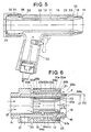
- Fig. 5 is a longitudinal section through a complete blowing tool according to the first embodiment of the invention.
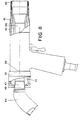
- Fig. 6 is a longitudinal section through a further modified nozzle according to the invention.
- Fig. 7 is an enlarged longitudinal section through a portion of a nozzle outlet according to an alternative embodiment of the nozzle according to Fig. 6.
- Fig. 8 shows the blowing tool according to Fig. 5 with additional devices according to the invention intended to be used preferably in the cleaning of so called bottom holes.
- Fig. 9 illustrates diagrammatically the operation of a blowing tool according to Fig. 8.
- Fig. 10 illustrates diagrammatically how the operation of a blowing tool according to Fig. 8 is affected by a disadvantageous relation between the overhang E and the diameter D1.
- Fig. 11 exemplifies the lifting capacity of a test body based upon the relation between the overhang E and the diameter D1 for a working blowing tool according to Fig. 8.
- The simplest embodiment of a "silent" nozzle for a
blowing device 10 according to the invention consists of aninner sleeve 11 and anouter sleeve 12, according to Fig. 1 and 2. The two sleeves may by themselves together constitute acomplete nozzle 13, preferably intended to be used in stationary installations. By means of a permanent connection, i.e. ascrew connection 14, the sleeves are interconnected, at their rear ends, to form a unit in such a manner, that there is formed, between thesleeves annular space 15 which serves as a supply channel for the compressed air. At the front end of the unit there is provided an outlet channel in the form of a substantiallyannular slot 16. - The blowing
device 10 further comprises aconnection 17 for the compressed air to thesupply channel 15 and anoutlet opening 18 in theinner sleeve 11. The outlet opening does not necessarily have to be conical as shown in the drawing. - When compressed air is supplied to the
nozzle 13 through theconnection 17, an annular jet C will be obtained at the outlet opening 19 of theslot 16. At the outlet opening, bound heat is transformed into kinetic energy under simultaneous expansion of the gas. A nozzle according to the invention is intended to be used for such types of work where the air pressure connected to the nozzle preferably is larger than 4 bar, i.e. the outflow from theoutflow opening 19 is mainly in the form of critical flow. - The object of the invention is attained with the nozzle embodiments according to the following descriptions.
- If in Fig. 1 the outer and inner diameters, respectively, of the
sleeves outlet opening 19 is designated by D1 and D2, respectively, then D2-D1=twice the slot measure S. In order to obtain a large contact surface between the outflowing gas or air and the surrounding air the nozzle according to the invention is provided with at least one communicatingchannel 20, i.e. in this way co-ejection is made possible outwardly peripherally as well as inwardly peripherally of the substantially annular flow. - In order to, in accordance with among other things one of the objects of the invention, delay the occurrence of the outgoing, substantially annular flow downstream of the outlet being integrated into a common flow with a large cross-sectional area with high velocity, the nozzle according to the invention has a cross-sectional ratio TF=D1/S which is larger than 3, preferably larger than 6. This in order that the ratio between the added up outlet circumference Oout and the added up outlet area Aout, comprising the contact number KT, multiplied with the cross-sectional ratio TF, together comprising a capacity number ET, will be substantially larger than 4 mm/mm2, preferably substantially larger than 10 mm/mm2. Thus, referring to Fig. 1, the relation 4 (D2+D1)/ D22-D1z) times the relation D1/S should be considerably larger than 4 mm/mm2 but preferably substantially larger than 10 mm/mm2.
- The indicated lower limit for the capacity number ET if "substantially larger than 4 mm/ mm2" is based upon the fact that dominant sound generation will hereby be displaced to higher frequencies which, in comparison with a conventional cylindrical tube outlet with the same blowing power, corresponds to a frequency displacement of about one octave.
- Hereby is obtained a sound pressure reduction which at the standardized middle frequency with a frequency width of one octave at 4 kHz will be about 2 dB and at the standardized
middle frequencies - This will cause a reduction of the dB(A)-filtered sound level of about 3 dB(A), i.e. at a capacity number of about 4 mm/mm2 will be obtained a lowering of the sound level which largely corresponds to the lowering which is necessary for a human being to subjectively notice the lowering of the sound level.
- Thus, the purpose of designing a blowing device with a capacity number of about 4 mm/ mm2 is that when a working blowing device is put up beside a working tubular nozzle, the blowing device according to the invention should be noticed as the decidedly more silent of the two.
- In blowing devices with a plurality of substantially part ring shaped slot outlets where the individual outlet may have different slot diameters corresponding to the diameter D1, Fig. 1 the diameter D1 according to the above will be defined as a mean value of the inner slot diameters of all the partial outlets.
- The slot S according to the above is defined as the mean value of the slot S computed over the actual number of slot outlets.
- At the normally occurring mass flow amounts at the most common forms of cleaning, the mean value computed slot S should be smaller than 3 mm, preferably smaller than 1.5 mm. This in order that dominant sound generation from the outlet will be found at frequencies higher than 20 kHz.
- The acoustical advantages of the nozzle thus described, are obtained i.a. thereby that the size of the unavoidable turbulency in the stream flow C is limited.
- High co-ejection due to a large contact surface between out-flowing air and surrounding air entails a rapidly decreasing velocity of flow but increase momentum.
- Thus the increased co-ejection means that the airstream will reach the work object in question with a lower velocity and a higher mass flow. This means that a nozzle according to the invention, in contrast to the so called noise' absorptive blow nozzles, has a substantially lower noise even when it is used as a working blowing tool.
- Tests performed with nozzles substantially corresponding to the description here above have been compared to most of the blow nozzles according to known embodiments. In all cases, a lower sound level and mostly markedly higher efficiency where noted. This while maintaining high blowing power. Compared to for instance the more usual tube nozzles there is obtained, already at such a low value of the capacity number ET as about 4 mm/mm2, a sound generation which is more than halved. The reduction of sound level will thereby be at least 3 dB(A). With a capacity number ET of about 10 mm/mm2, the sound generation may be reduced to at least one third. At considerably higher values of the capacity number, very noticeable reductions in sound level have been noted. With a capacity number ET of about 500 mm/mm2 the sound generation may for instance be reduced to less than one tenth, and with a capacity number of about 5.900 MM/MM 2 with up to one hundredth of the sound generation in traditional tube nozzles with the same amount of mass flow and/or blowing power.
- Thus, the comprehensive tests have shown that, compared to a tubular nozzle with the same outlet area, a noise reduction in dB(A) is obtained which, at critical flow, is substantially proportional to 5 times the 10-logarithm for the capacity number ET.
- Since, from the point of view of sound, it is of importance that the inner diameter D2 of the
outer sleeve 12 is substantially concentric with the mantle surface of theinner sleeve 11,spacing elements 22 centering the sleeves relative to one another are provided on one or both of the sleeves. - When the nozzle lacks the regulation possibility, according to Fig. 3 and 5, while maintaining the advantages of the nozzle the corresponding spacing elements may be disposed in the
annular slot 16 which may then be made with axial grooves, where the upper edge of the grooves abut against the inner side of theouter sleeve 12 or vice versa, that the grooves are provided at the inner side of theouter sleeve 12 and abut against theinner sleeve 11. - Thus, the annular outflow may not be completely cylindrical, but the flow may be divided in a number of flows shaped as a part of a ring. Also, these need not necessarily be situated along a common division diameter.
- In order to reduce that pressure variations occurring within the
supply channel 15 affects the pressure situation at theoutlet 19 theannular slot 16 should be longer than 4 times the slot measure. - When creating extremely high blowing powers per surface unit, for instance when blowing away parts from automatic machines, it may be of advantage, from the point of view of noise, two provide a number of substantially circular through-
flow channels 23, according to Fig. 4 within the nozzle portion of theinner sleeve 11, instead of increasing the slot measure S. The diameter of thecircular outlet channels 23 should be smaller than 2 mm, preferably smaller than 1.7 mm, and should be placed at a distance relative to each other which is larger than 2 times their diameter. - If a
blowing device 10 is desired which is to allow a regulation of the amount of flow of air, the nozzle and theblowing device 10 is made as appears from Fig. 3 and 5. By the aid of aregulation nut 31 which cooperates withthreads 32 at the rear end of theouter sleeve 12 theinner sleeve 11 may be axially displaced against the action of aspring 33. - When the two
sleeves annular slot 16 are angled in relation to thelongitudinal axes 27 of the nozzle, see Fig. 3. Theangles surfaces 23 and 24 may, relative to the direction of flow, be converging relative to thelongitudinal axes 27 of the nozzle. The amount of air through one and the same way in this way be regulated within very wide limits. Furthermore, the regulation is substantially linear. The outer and the inner sleeve, respectively may advantageously be provided withmarkings 39 concerning the size of the blowing power. - In the embodiment according to Fig. 5, the outer sleeve of the
blowing device 10 constitutes a portion of thebase 30 of the device. Saidregulation nut 31 is screwed onto the rear portion of the base, and in order to reduce the friction of movement between theinner sleeve 11 and theregulation nut 31, one or several roller orball elements 34 are provided within the rear end plane of the inner sleeve. - In the drawing position shown the inner sleeve has its front position within the
base 30, i.e. theshoulder 35 of the inner sleeve bears against theshoulder 36 base. - At preferably higher needs of blowing power it is of advantage to subdivide a ring shape or part-ring shaped flow into one or several further substantially ring- and/or part-ring shaped flows where the inner and outer limiting surfaces of the respective flows have the possibility of co-ejection-for instance as in the nozzle according to Fig. 6. In the Fig. the co-ejection routes are indicated with arrows.
- Hereby, the increase in the capacity number ET may be multiplied while maintaining the added up outlet area A. This because the slot measure S for the respective part flows will then be more than halved. Dominant sound generation will be displaced to still higher frequencies. Because the frequency to which dominant sound generation occurs is inversely proportional to the slot measure S of the air flow.
- Furthermore, with a correctly controlled outflows as regards pressure, density and velocity, the embodiment with an increased number of outlets will give the possibility of further sound reductions relative to the amount of mass flow present. Further, by the aid of at least one substantial annular additional flow in the surrounding around a mainflow, the latter may be imparted with over-critical flow the radiated higher sound effect of which will interfere, to substantial parts, with pressure pulses present within surrounding additional flows.
- The embodiment according to Fig. 6 may be an addition to the
blowing device 10 according to Fig. 1. In a first step the blowingdevice 10 may be provided with an outer nozzle part 50a which consists of twocylindrical sleeves inner sleeve 51 a is connected, by means of a pressfit, a groove or screw connection, via thespacer elements 53, with theouter sleeve 12 of theblowing device 10. - The
spacer elements 53 are shaped in accordance with the same principle as thespacers 22 in Fig. 1. Within at least onespacer element 53 there is a through-flow passage 54a which is supplied with pressurized air from thesupply channel 15 via the chamber 55a. - The
space 56a between the twonozzle outlets - As a second step the blowing 10 may advantageously be provided with an
inner nozzle part 50b. As shown in Fig. 6, this may be shaped substantially at the outer nozzle part 50a. - With a nozzle embodiment with at least two annularly shaped partial flows, the surrounded
flow 16 will obtain, with adjustment of the amount of mass flow for the surrounding flows from theoutlets 57a and/or 57b, a counter pressure downstreams of the outlet which is substantially lower than the critical pressure. That is, the counter pressure downstreams of theoutlet 16 may be made less than 0.528 times the supply pressure connected to theblowing device 10. - The annular nozzle outlet 16 (Fig. 7) is adjusted to give over-critical outflow at the
outlet 16 of theblowing device 10. In order to reach an over-critical flow at theoutlet 16, the capacity number ET in this embodiment should be at least 20 mm/mm2, preferably larger than 100 mm/mm2. Further, the relation between D122_D11 2=G and D2z-D12=H should be less than 1.7 at an available supply pressure of 8 bar. At an available supply pressure of 6 bar, G/H should be less than 1.45. The latter entails a velocity increase by a factor of 1.55. The angle V should be 3-6°. - Available velocity increases for the
outlet 16 will allow savings of air by 20-30% while maintaining blowing power. - Acoustically achieved advantages with the over-critical flow mentioned is that for a given mass flow and/or blowing power the outlet velocity will increase while the slot measure S is reduced. Dominant sound generation may thereby be displaced to even higher frequencies, because the frequency to which dominant sound generation occurs is directly proportional to the velocity of the airflow and inversely proportional to the slot measure S of the airflow.
- The blowing device according to Fig. 5 may be converted into a blowing a blowing tool for cleaning so called bottom holes as shown in Fig. 8.
- To the
nozzle end 13 of the blowing device there is connectable aprotective collar 41 consisting of a thin-walled tube of plastic or sheet metal and provided with abrush element 44 intended to be placed against an object to be blown clean, for instance a hole. Since the resistance against flow of the brush element is considerably larger than the resistance against flow in the communicatingchannel 20, the cleaning air will be evacuated through said channel. Thebrush element 44 may of course be replaced with some other flexible material such as foamed plastic or moulded rubber. By connecting the communicatingchannel 20 to a collectingdevice 45, i.e. to a centrally service suction conduit, alternatively to a collecting bag, which, for instance by means of aninsertion tube 47 is connected to aconical seat 48 in theinner sleeve 11, large reductions in sound level are obtained. - Tests that have been made have shown that a blowing tool substantially corresponding to Fig. 8 will reduce the momentarily occurring sound peaks with more than 20 dB(A). Hereby, the amount of noise during a typical working day may be reduced by 7-10 dB(A). The nozzle gives an airflow with an impact surface substantially corresponding to the diameter of the
brush element 44. Thus, the blowing operation may be started directly after that the brush element has been placed above the hole to be blown clean, whereby uncontrolled squirting of chips and cutting fluid will be eliminated. Furthermore, there will be no risk for mechanical abrasion on the blowing tool or the object to be blown clean. - Tests which has been made have shown that when the overhang E is well adapted in relation to the diameter D1 of the
outlet channel 16, a flow picture is obtained which is illustrated diagrammatically in Fig. 9. - Within the zone P10 there will be formed a turbulent air cushion which is at rest in relation to the air stream and which has a higher static pressure and guides the flow to the
hole 15 to be blown clean. - When the overhang is too small, as diagrammatically illustrated in Fig. 10, a flow picture is obtained which does not have the ability of cleaning the
hole 50. That is, a small measure E and the small air cushion P11 will cause a direction of movement which very much diverges from the optimum direction of movement from the point of view of the cleaning. It should also be pointed out that also a too large overhang E gives a deteriorated blowing clean function. However, in this case, the divergence from optimum working function may be compensated to a certain extent by an increased mass flow through the blowing device. - Tests which have been made have shown that the clean blowing function is dependent upon the diameter D1 of the ring- or part-ring shaped outlet, the overhang E and the cross and longitudinal dimensions of the
hole 50. - Variations in hole dimensions may be compensated to a large degree by varying the mass flow through the blowing device.
- Fig. 11 illustrates how, in a test with one and the same amount of mass flow, the lifting height of a test body varies depending upon the ratio E/D1. Lifting height here means the distance between the
plane 51 of the work object and a reference plane which is placed behind which is positioned in the vertical plane. The test body which was placed in the bottom of a hole standing in the vertical plane (here with thediameter 10 mm and the depth of the hole about 30 mm) was thus distributed via thecommunication channel 20 of the blowing device and thereafter via the atmosphere to the reference plane. The distance of the reference plane to theplane 51 was adjusted so that the test body could hit the same with a slight margin. - In order to obtain a sufficiently good work function for most different hole dimensions at the
hole 50, the relation between the overhang E of the protective collar and the mean value inner diameter D1 for the ring- or part-ring shaped outlet (S) should be greater than 0.6 and smaller than 12.7. However, preferably the relation should be greater than 1.2 and less than 8. - The
communication channel 20 need not necessarily, as shown in Fig. 8, be constituted by a single channel. Further, the ring- or part-ring shapedoutlets 19 need not be constituted by slot- shapedchannels 16, but the substantially ring- or part-ring shaped flow within theprotective collar 41 may be formed by an outlet consisting of a series of cylindrical channels, as thechannels 23 in Fig. 4. - When the blowing tool may be used in the matter described for the clean-blowing of holes, grooves etc. the essential of being able to continually regulating the blowing power will be more clearly apparent. This since the total pressure drop through the collecting bag 46 will vary with respect to the degree of filling, but above all, with respect to the fact that different hole shapes, types of cutting fluid, etc. demands different blowing power. A regulation may easily be made by means of the fitting of the regulating means 31.
Claims (10)
Priority Applications (1)
| Application Number | Priority Date | Filing Date | Title |
|---|---|---|---|
| AT82903488T ATE26546T1 (en) | 1981-11-18 | 1982-11-17 | BLOW NOZZLE FOR SILENT GAS FLOW. |
Applications Claiming Priority (2)
| Application Number | Priority Date | Filing Date | Title |
|---|---|---|---|
| SE8106856 | 1981-11-18 | ||
| SE8106856 | 1981-11-18 |
Publications (2)
| Publication Number | Publication Date |
|---|---|
| EP0105279A1 EP0105279A1 (en) | 1984-04-18 |
| EP0105279B1 true EP0105279B1 (en) | 1987-04-15 |
Family
ID=20345060
Family Applications (1)
| Application Number | Title | Priority Date | Filing Date |
|---|---|---|---|
| EP82903488A Expired EP0105279B1 (en) | 1981-11-18 | 1982-11-17 | A blowing nozzle for silent outflow of gas |
Country Status (9)
| Country | Link |
|---|---|
| US (1) | US4592509A (en) |
| EP (1) | EP0105279B1 (en) |
| JP (1) | JPS58501940A (en) |
| AT (1) | ATE26546T1 (en) |
| AU (1) | AU9127982A (en) |
| DE (1) | DE3276051D1 (en) |
| DK (1) | DK315583A (en) |
| NO (1) | NO832561L (en) |
| WO (1) | WO1983001747A1 (en) |
Families Citing this family (27)
| Publication number | Priority date | Publication date | Assignee | Title |
|---|---|---|---|---|
| EP0212195B1 (en) * | 1985-07-16 | 1990-03-28 | Starrfräsmaschinen AG | Dust decrease and chip transferring and apparatus on a machine tool work station |
| SE451362B (en) * | 1985-08-09 | 1987-10-05 | Hans Bengt Folke Moss | BLASMUNSTYCKE |
| US4826084A (en) * | 1986-09-26 | 1989-05-02 | Wallace Norman R | Sheathed jet fluid dispersing apparatus |
| FR2639404B1 (en) * | 1988-11-21 | 1994-04-15 | Propulsion Ste Europeenne | DIVERGENT OF MOTOR ROCKET WITH ADDITIONAL ANNULAR NOZZLE |
| FR2703264B1 (en) * | 1993-03-30 | 1995-07-28 | York France Sa | Spray nozzle and device for spraying a mixture of water and air using said nozzle. |
| US5863229A (en) * | 1996-06-11 | 1999-01-26 | Bombardier, Inc. | Variable venturi |
| WO1999041506A1 (en) * | 1998-02-13 | 1999-08-19 | Petrukhin, Evgeny Dmitrievich | Liquid-gas jet apparatus |
| GB2335731B (en) * | 1998-03-27 | 2001-12-19 | Anthony Michael Glazer | A cryostat nozzle and a method of using a cryostat |
| DE20106613U1 (en) * | 2001-04-17 | 2001-07-12 | Horn Franziskus | Nozzle for using hydrogen phosphide |
| US6601782B1 (en) | 2002-12-23 | 2003-08-05 | Plas-Pak Industries, Inc. | Disposable spray nozzle assembly |
| US7427039B1 (en) * | 2007-03-23 | 2008-09-23 | Wuu-Cheau Jou | Siphon drying gun |
| EP2293926B1 (en) * | 2008-06-06 | 2016-05-04 | Novartis AG | Drying nozzle and method of drying |
| DE102010014580A1 (en) * | 2010-04-09 | 2011-10-13 | Dieter Wurz | Multi-fuel nozzle with primary gas jet |
| FR2985202A1 (en) | 2012-01-03 | 2013-07-05 | Oreal | HEAD OF DISTRIBUTION |
| FR2985201B1 (en) * | 2012-01-03 | 2016-01-08 | Oreal | HOLLOW DISTRIBUTION HEAD |
| KR101983111B1 (en) | 2012-07-04 | 2019-05-29 | 다이슨 테크놀러지 리미티드 | Attachment for a hand held appliance |
| US9534848B2 (en) * | 2012-08-28 | 2017-01-03 | Kla-Tencor Corporation | Method and apparatus to reduce thermal stress by regulation and control of lamp operating temperatures |
| US9266140B2 (en) * | 2012-11-21 | 2016-02-23 | Lockheed Martin Corporation | Annular adhesive bead application |
| FR3007952B1 (en) * | 2013-07-04 | 2015-07-24 | Oreal | AEROSOL CONTAINING AN EMULSION DEODORANT EQUIPPED WITH A HOLLOW DISTRIBUTION HEAD |
| FR3007953B1 (en) * | 2013-07-04 | 2015-07-24 | Oreal | AEROSOL ALCOHOLIC DEODORANT EQUIPPED WITH A HOLLOW DISTRIBUTION HEAD |
| US20160010556A1 (en) * | 2014-07-10 | 2016-01-14 | Delavan, Inc. | Fluid nozzle and method of distributing fluid through a nozzle |
| EP3347774A4 (en) * | 2015-09-11 | 2019-05-08 | Henkel IP & Holding GmbH | Remote adhesive monitoring system |
| US20200230624A1 (en) * | 2017-10-24 | 2020-07-23 | Nsk Ltd. | Nozzle structure, blowing device, and method for producing components, bearings, direct-acting devices, steering devices and vehicles |
| CN109693884A (en) * | 2019-01-29 | 2019-04-30 | 中山市美捷时包装制品有限公司 | A kind of annular aerosol actuator |
| CN110605277A (en) * | 2019-09-27 | 2019-12-24 | 重庆方正高密电子有限公司 | Scrap removing device and riveting machine |
| US11931199B2 (en) * | 2021-01-28 | 2024-03-19 | Yuri Abramov | Nozzles for amplifying and suppression of sound |
| CN115069435A (en) * | 2022-06-24 | 2022-09-20 | 广西玉柴机器股份有限公司 | Low-noise air blowing nozzle |
Family Cites Families (8)
| Publication number | Priority date | Publication date | Assignee | Title |
|---|---|---|---|---|
| US2543517A (en) * | 1947-06-09 | 1951-02-27 | Jo Zach Miller Iii | Apparatus for combining and emplacing cementitious substances |
| US3477112A (en) * | 1968-03-08 | 1969-11-11 | Goss Gas Inc | Method for forming torch tips |
| US3615053A (en) * | 1970-06-16 | 1971-10-26 | Bethlehem Steel Corp | Gas pressure regulated atomizer tip for gas/oil burner |
| DK134847A (en) * | 1970-10-22 | |||
| US3770204A (en) * | 1971-12-27 | 1973-11-06 | F Schuster | Cleaning and removal device |
| US4311404A (en) * | 1977-07-07 | 1982-01-19 | Masao Kodera | Sprinkler brush assembly |
| CA1077541A (en) * | 1977-12-01 | 1980-05-13 | Vortec Corporation | Flow amplifying nozzle |
| DE2908004A1 (en) * | 1979-03-01 | 1980-09-04 | Herbert Nowotzin | Tool for removing swarf from blind holes - uses jet of air which returns through outer pipe surrounding jet pipe |
-
1982
- 1982-11-17 EP EP82903488A patent/EP0105279B1/en not_active Expired
- 1982-11-17 DE DE8282903488T patent/DE3276051D1/en not_active Expired
- 1982-11-17 WO PCT/SE1982/000388 patent/WO1983001747A1/en active IP Right Grant
- 1982-11-17 AU AU91279/82A patent/AU9127982A/en not_active Abandoned
- 1982-11-17 JP JP57503456A patent/JPS58501940A/en active Pending
- 1982-11-17 US US06/530,595 patent/US4592509A/en not_active Expired - Lifetime
- 1982-11-17 AT AT82903488T patent/ATE26546T1/en not_active IP Right Cessation
-
1983
- 1983-07-08 DK DK315583A patent/DK315583A/en not_active Application Discontinuation
- 1983-07-14 NO NO832561A patent/NO832561L/en unknown
Also Published As
| Publication number | Publication date |
|---|---|
| AU9127982A (en) | 1983-06-01 |
| US4592509A (en) | 1986-06-03 |
| DE3276051D1 (en) | 1987-05-21 |
| EP0105279A1 (en) | 1984-04-18 |
| DK315583D0 (en) | 1983-07-08 |
| ATE26546T1 (en) | 1987-05-15 |
| DK315583A (en) | 1983-07-08 |
| JPS58501940A (en) | 1983-11-17 |
| NO832561L (en) | 1983-07-14 |
| WO1983001747A1 (en) | 1983-05-26 |
Similar Documents
| Publication | Publication Date | Title |
|---|---|---|
| EP0105279B1 (en) | A blowing nozzle for silent outflow of gas | |
| US4322027A (en) | Filament draw nozzle | |
| KR920007952B1 (en) | Descaling nozzle | |
| US4195780A (en) | Flow amplifying nozzle | |
| US3984054A (en) | Nozzle | |
| US6047903A (en) | Fluid flow conditioner | |
| Karmeli | Classification and flow regime analysis of drippers | |
| US3814329A (en) | Pressure reducing nozzles for pressure guns | |
| JP2637626B2 (en) | Flat jet nozzle for high pressure cleaning equipment | |
| DE69832956D1 (en) | NOZZLE OF A FLOW REGULATOR WITH A PRESSURE REGULATION AND METHOD OF MANUFACTURING THEREOF | |
| CA2259555A1 (en) | Nozzle assembly for a spray head | |
| US4867380A (en) | Pistol grip type compressed air blower | |
| EP0521051B1 (en) | An air nozzle for a directed discharge of air into a room | |
| US4431135A (en) | Air nozzle and method | |
| US4760957A (en) | Flow regulator and water sprinkler including same | |
| SE439441B (en) | SET TO REDUCE SOUND STRING AT THE MULTI-CHANNEL NOZZLE AND MULTI-CHANNEL NOZZLE FOR IMPLEMENTATION OF THE SET | |
| US4523718A (en) | Showerhead | |
| EP0030927A1 (en) | Blowing nozzle | |
| US4107828A (en) | Yarn treating jet | |
| EP0181157A2 (en) | Yarn texturing jet | |
| US4256263A (en) | Spray nozzle for shower apparatus | |
| GB1602127A (en) | Spray nozzle for shower apparatus | |
| US6431470B2 (en) | Low-noise air nozzle | |
| GB1507650A (en) | Spray nozzle | |
| SU904862A1 (en) | Apparatus for blowing-off formed parts and scale |
Legal Events
| Date | Code | Title | Description |
|---|---|---|---|
| PUAI | Public reference made under article 153(3) epc to a published international application that has entered the european phase |
Free format text: ORIGINAL CODE: 0009012 |
|
| 17P | Request for examination filed |
Effective date: 19831128 |
|
| AK | Designated contracting states |
Designated state(s): AT CH DE FR GB LI NL SE |
|
| GRAA | (expected) grant |
Free format text: ORIGINAL CODE: 0009210 |
|
| AK | Designated contracting states |
Kind code of ref document: B1 Designated state(s): AT CH DE FR GB LI NL SE |
|
| REF | Corresponds to: |
Ref document number: 26546 Country of ref document: AT Date of ref document: 19870515 Kind code of ref document: T |
|
| REF | Corresponds to: |
Ref document number: 3276051 Country of ref document: DE Date of ref document: 19870521 |
|
| ET | Fr: translation filed | ||
| PGFP | Annual fee paid to national office [announced via postgrant information from national office to epo] |
Ref country code: NL Payment date: 19871130 Year of fee payment: 6 |
|
| PLBE | No opposition filed within time limit |
Free format text: ORIGINAL CODE: 0009261 |
|
| STAA | Information on the status of an ep patent application or granted ep patent |
Free format text: STATUS: NO OPPOSITION FILED WITHIN TIME LIMIT |
|
| 26N | No opposition filed | ||
| PG25 | Lapsed in a contracting state [announced via postgrant information from national office to epo] |
Ref country code: GB Effective date: 19881117 Ref country code: AT Effective date: 19881117 |
|
| PG25 | Lapsed in a contracting state [announced via postgrant information from national office to epo] |
Ref country code: SE Effective date: 19881118 |
|
| PG25 | Lapsed in a contracting state [announced via postgrant information from national office to epo] |
Ref country code: LI Effective date: 19881130 Ref country code: CH Effective date: 19881130 |
|
| PGFP | Annual fee paid to national office [announced via postgrant information from national office to epo] |
Ref country code: FR Payment date: 19890530 Year of fee payment: 7 |
|
| PG25 | Lapsed in a contracting state [announced via postgrant information from national office to epo] |
Ref country code: NL Effective date: 19890601 |
|
| NLV4 | Nl: lapsed or anulled due to non-payment of the annual fee | ||
| GBPC | Gb: european patent ceased through non-payment of renewal fee | ||
| PGFP | Annual fee paid to national office [announced via postgrant information from national office to epo] |
Ref country code: DE Payment date: 19890727 Year of fee payment: 7 |
|
| REG | Reference to a national code |
Ref country code: CH Ref legal event code: PL |
|
| PG25 | Lapsed in a contracting state [announced via postgrant information from national office to epo] |
Ref country code: FR Effective date: 19900731 |
|
| PG25 | Lapsed in a contracting state [announced via postgrant information from national office to epo] |
Ref country code: DE Effective date: 19900801 |
|
| REG | Reference to a national code |
Ref country code: FR Ref legal event code: ST |
|
| EUG | Se: european patent has lapsed |
Ref document number: 82903488.3 Effective date: 19890726 |