EP0105094A2 - Flugüberwachungsverfahren eines magnetischen Umwandlungskopf - Google Patents
Flugüberwachungsverfahren eines magnetischen Umwandlungskopf Download PDFInfo
- Publication number
- EP0105094A2 EP0105094A2 EP83106491A EP83106491A EP0105094A2 EP 0105094 A2 EP0105094 A2 EP 0105094A2 EP 83106491 A EP83106491 A EP 83106491A EP 83106491 A EP83106491 A EP 83106491A EP 0105094 A2 EP0105094 A2 EP 0105094A2
- Authority
- EP
- European Patent Office
- Prior art keywords
- head
- magnetic
- disk
- contact
- record medium
- Prior art date
- Legal status (The legal status is an assumption and is not a legal conclusion. Google has not performed a legal analysis and makes no representation as to the accuracy of the status listed.)
- Granted
Links
Images
Classifications
-
- G—PHYSICS
- G11—INFORMATION STORAGE
- G11B—INFORMATION STORAGE BASED ON RELATIVE MOVEMENT BETWEEN RECORD CARRIER AND TRANSDUCER
- G11B5/00—Recording by magnetisation or demagnetisation of a record carrier; Reproducing by magnetic means; Record carriers therefor
- G11B5/48—Disposition or mounting of heads or head supports relative to record carriers ; arrangements of heads, e.g. for scanning the record carrier to increase the relative speed
- G11B5/58—Disposition or mounting of heads or head supports relative to record carriers ; arrangements of heads, e.g. for scanning the record carrier to increase the relative speed with provision for moving the head for the purpose of maintaining alignment of the head relative to the record carrier during transducing operation, e.g. to compensate for surface irregularities of the latter or for track following
- G11B5/60—Fluid-dynamic spacing of heads from record-carriers
- G11B5/6005—Specially adapted for spacing from a rotating disc using a fluid cushion
-
- G—PHYSICS
- G11—INFORMATION STORAGE
- G11B—INFORMATION STORAGE BASED ON RELATIVE MOVEMENT BETWEEN RECORD CARRIER AND TRANSDUCER
- G11B21/00—Head arrangements not specific to the method of recording or reproducing
- G11B21/16—Supporting the heads; Supporting the sockets for plug-in heads
- G11B21/20—Supporting the heads; Supporting the sockets for plug-in heads while the head is in operative position but stationary or permitting minor movements to follow irregularities in surface of record carrier
-
- G—PHYSICS
- G11—INFORMATION STORAGE
- G11B—INFORMATION STORAGE BASED ON RELATIVE MOVEMENT BETWEEN RECORD CARRIER AND TRANSDUCER
- G11B33/00—Constructional parts, details or accessories not provided for in the other groups of this subclass
- G11B33/10—Indicating arrangements; Warning arrangements
-
- G—PHYSICS
- G11—INFORMATION STORAGE
- G11B—INFORMATION STORAGE BASED ON RELATIVE MOVEMENT BETWEEN RECORD CARRIER AND TRANSDUCER
- G11B5/00—Recording by magnetisation or demagnetisation of a record carrier; Reproducing by magnetic means; Record carriers therefor
- G11B5/48—Disposition or mounting of heads or head supports relative to record carriers ; arrangements of heads, e.g. for scanning the record carrier to increase the relative speed
- G11B5/58—Disposition or mounting of heads or head supports relative to record carriers ; arrangements of heads, e.g. for scanning the record carrier to increase the relative speed with provision for moving the head for the purpose of maintaining alignment of the head relative to the record carrier during transducing operation, e.g. to compensate for surface irregularities of the latter or for track following
- G11B5/60—Fluid-dynamic spacing of heads from record-carriers
-
- G—PHYSICS
- G11—INFORMATION STORAGE
- G11B—INFORMATION STORAGE BASED ON RELATIVE MOVEMENT BETWEEN RECORD CARRIER AND TRANSDUCER
- G11B5/00—Recording by magnetisation or demagnetisation of a record carrier; Reproducing by magnetic means; Record carriers therefor
- G11B5/62—Record carriers characterised by the selection of the material
- G11B5/68—Record carriers characterised by the selection of the material comprising one or more layers of magnetisable material homogeneously mixed with a bonding agent
- G11B5/70—Record carriers characterised by the selection of the material comprising one or more layers of magnetisable material homogeneously mixed with a bonding agent on a base layer
- G11B5/708—Record carriers characterised by the selection of the material comprising one or more layers of magnetisable material homogeneously mixed with a bonding agent on a base layer characterised by addition of non-magnetic particles to the layer
Definitions
- This invention relates to a method of monitoring the flight of a magnetic transducer head as it flies on an air bearing over a magnetic record medium.
- a method of monitoring the flight of a magnetic transducer head on an air bearing over a magnetic record medium comprises, according to the invention, detecting triboelectric charges generated by intermittent contacts between the head and the record medium.
- the invention utilizes the natural charge transfer of two bodies of different material which are in motion relative to each other to generate signals which give an indication of any intermittent contacts between the bodies and which also give a measure of spacing changes between the bodies when they are not in contact.
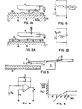
- FIG. 1A is a representation of the generation of triboelectric charges by intermittent contact between a magnetic head in a slider assembly and the surface of a magnetic recording disk.
- the slider assembly 11, which carries a magnetic transducer for writing and reading on the magnetic recording surface, may be of any suitable type such as that shown in US-A-3,855,625.
- Disk 12 includes a metallic substrate 12a on which is deposited a magnetic recording layer 12b.
- Layer 12b may be of any suitable type, such as that described in US-A-3,058,844, including an epoxy-phenolic binder system having magnetic particles of gamma Fe 2 0 3 dispersed therein.
- Metallic film disk- layer 12b may also include head load-bearing particles 12c of a suitable material, such as A1 2 0 3 , as taught in U.S. Reissue Patent 28,866.
- These particles 12c are usually larger than the magnetic particles in the coating and some of them may protrude above the nominal surface of layer 12b, even after buffing and polishing of the disk surface. As shown in FIG. lA, one such load- bearing particle 12c is shown making a momentary contact with the air bearing surface of slider 11. Because the material of slider 11 and that of the magnetic recording layer 12 are different in the triboelectric series, this contact generates a triboelectric charge which is utilized in the present invention to monitor the occurrence of such contacts. The electrical equivalent of this is shown in FIG.
- magnetic recording disks which contain magnetic iron oxide or other deposited magnetic layers hold a permanent electric charge, much like an electret. This results in a constant electric potential of approximately 300 millivolts measured between the air above the surface of recording disk 12 and the disk substrate 12a.
- a flying conductive head whose spacing from the disk surface varies during disk rotation generates a displacement current which is directly proportional to the spacing modulation dz/dt. This is shown in FIG. 2A with conductive slider 11 moving in the z direction above the surface of magnetic recording disk 12. The electrical equivalent of this is shown in FIG.
- the current is what is known in the art as displacement current, being generated by a time-varying capacitor in series with a substantially constant voltage source, which is the bound electret charge in the disk coating.
- Detection of both the triboelectric charges generated by contacts between the slider and the disk surface and the modulation produced by variations in the spacing between the slider and the disk provides continuous monitoring of both the occurrence and severity of such contacts and variations in the spacing when the slider and disk are not in contact.
- FIG. 3 The essential elements of an arrangement for monitoring the flight of a head over a disk are shown in FIG. 3, and include:
- One preferred embodiment for the current measuring circuitry 19 is a single operational amplifier connected in the "trans-impedance" mode as shown in FIG 4.
- R 1 is selected to minimize the dc offset voltage at V o .
- C SD is the slider-to-disk capacitance, a typical value being approximately 10 -10 Farads, when the slider is in flight.
- C F , R are a feedback capacitor and resistor, respectively. Their values are selected to give the closed-loop frequency response shown in FIG. 5. This is given by the equation: j equals the square root of -1
- trans-impedance circuitry is well known, see, for example, Operational Amplifiers, edited by Tobey, Graeme and Huelsman, McGraw-Hill, 1971.
- the closed loop response is tailored to detect both the glide (non-contact) and the contact modes of the slider. These modes are separated in the frequency domain.
- the glide mode frequency being directly set by the effective mass (M) of the slider and the air-bearing stiffness (k) is band-limited.
- This f in FIG. 5 is set to be slightly above the glide mode frequency; Typically, this is about 50 Kilo-Hertz for present day sliders.
- the circuitry in FIG. 4 acts as a current-to-voltage converter.
- the circuitry acts as an inverting charge amplifier.
- the material composition of the disk protrusions can be differentiated and classified.
- Another important advantage of the present method is that no extra transducer is fabricated onto the slider and that no external measuring voltages or currents are injected into the slider/disk interface. Thus, the actual magnetic components are used to perform disk testing.
- the disks can be monitored continuously throughout their operating life.
Landscapes
- Manufacturing Of Magnetic Record Carriers (AREA)
- Measurement Of Length, Angles, Or The Like Using Electric Or Magnetic Means (AREA)
Applications Claiming Priority (2)
| Application Number | Priority Date | Filing Date | Title |
|---|---|---|---|
| US431404 | 1982-09-30 | ||
| US06/431,404 US4479090A (en) | 1982-09-30 | 1982-09-30 | Circuitry for measuring magnetic head flying characteristics |
Publications (3)
| Publication Number | Publication Date |
|---|---|
| EP0105094A2 true EP0105094A2 (de) | 1984-04-11 |
| EP0105094A3 EP0105094A3 (en) | 1985-12-11 |
| EP0105094B1 EP0105094B1 (de) | 1988-11-09 |
Family
ID=23711794
Family Applications (1)
| Application Number | Title | Priority Date | Filing Date |
|---|---|---|---|
| EP83106491A Expired EP0105094B1 (de) | 1982-09-30 | 1983-07-04 | Flugüberwachungsverfahren eines magnetischen Umwandlungskopf |
Country Status (4)
| Country | Link |
|---|---|
| US (1) | US4479090A (de) |
| EP (1) | EP0105094B1 (de) |
| JP (1) | JPS5965972A (de) |
| DE (1) | DE3378435D1 (de) |
Cited By (7)
| Publication number | Priority date | Publication date | Assignee | Title |
|---|---|---|---|---|
| EP0203207A1 (de) * | 1985-05-10 | 1986-12-03 | Ibm Deutschland Gmbh | System zur Prüfung von Grenzflächen zwischen Magnetkopf und Platte |
| EP0227845A1 (de) * | 1985-11-19 | 1987-07-08 | International Business Machines Corporation | Verfahren und Vorrichtung zur Regelung der Flughöhe des Kopfes in einem Magnetspeicher |
| EP0248092A1 (de) * | 1986-04-04 | 1987-12-09 | Ibm Deutschland Gmbh | Arbeitsüberwachungsverfahren einer Kopf-Platten-Trennfläche und Gerät zum Verhindern von Datenverlusten infolge von Kopf-Platten-Interferenzen |
| EP0294761A1 (de) * | 1987-06-11 | 1988-12-14 | International Business Machines Corporation | Verfahren und Vorrichtung zur Vermeidung eines Stosses des magnetischen Wandlers auf das Magnetsubstrat |
| EP0326756A1 (de) * | 1988-01-14 | 1989-08-09 | International Business Machines Corporation | Verfahren und Vorrichtung zum Detektieren von abnormaler Arbeitsweise eines Gerätes mit bewegbarem Speicher |
| US5021906A (en) * | 1989-10-31 | 1991-06-04 | International Business Machines Corporation | Programmable air bearing slider including magnetic read/write element |
| US5623383A (en) * | 1994-06-30 | 1997-04-22 | International Business Machines | Magnetic slider design for precision wear-in |
Families Citing this family (10)
| Publication number | Priority date | Publication date | Assignee | Title |
|---|---|---|---|---|
| US5247448A (en) * | 1991-01-31 | 1993-09-21 | Seagate Technology, Inc. | Using spectral signature analysis in producing substrates for magnetic media |
| US5450747A (en) * | 1993-12-27 | 1995-09-19 | International Business Machines Corporation | Method for optimizing piezoelectric surface asperity detection sensor |
| US5539592A (en) * | 1994-10-05 | 1996-07-23 | International Business Machines Corporation | System and method for monitoring friction between head and disk to predict head disk interaction failure in direct access storage devices |
| US5706080A (en) * | 1996-12-09 | 1998-01-06 | Phase Metrics | Single test station that can test a flying height and electrical characteristics of a recording head |
| US20030102218A1 (en) * | 1997-07-28 | 2003-06-05 | Kiely James Dillon | Head-disk stiction reduction |
| GB2330910A (en) * | 1997-11-01 | 1999-05-05 | Ford Motor Co | Identification of friction materials |
| AU2003210457A1 (en) * | 2002-01-07 | 2003-07-24 | Seagate Technology Llc | Head-disk stiction reduction |
| US20050174665A1 (en) * | 2004-02-09 | 2005-08-11 | Xiaofeng Zhang | Electrical current measurements at head-disk interface |
| US8139306B2 (en) | 2004-02-09 | 2012-03-20 | Sae Magnetics (Hk) Ltd. | Electrical current as probe for modulation at head-disk interface |
| US9042208B1 (en) * | 2013-03-11 | 2015-05-26 | Western Digital Technologies, Inc. | Disk drive measuring fly height by applying a bias voltage to an electrically insulated write component of a head |
Family Cites Families (8)
| Publication number | Priority date | Publication date | Assignee | Title |
|---|---|---|---|---|
| US568205A (en) * | 1896-09-22 | Mortimer norden | ||
| US3601694A (en) * | 1968-12-09 | 1971-08-24 | Eastman Kodak Co | Apparatus for electrically checking the continuity of a coating |
| US3737569A (en) * | 1969-02-26 | 1973-06-05 | Xerox Corp | Transmission device |
| USRE28866E (en) * | 1972-09-18 | 1976-06-15 | International Business Machines Corporation | Magnetic recording coating |
| US3855625A (en) * | 1973-12-19 | 1974-12-17 | Ibm | Magnetic head slider assembly |
| US4167765A (en) * | 1978-07-27 | 1979-09-11 | International Business Machines Corporation | Transducer suspension mount apparatus |
| DE3036928A1 (de) * | 1980-09-30 | 1982-05-13 | Siemens AG, 1000 Berlin und 8000 München | Vorrichtung zum abgleichen der ladungsverstaerker fuer die piezokoepfe in plattenspeichern |
| US4325134A (en) * | 1980-10-15 | 1982-04-13 | Rca Corporation | Video disc defect detector |
-
1982
- 1982-09-30 US US06/431,404 patent/US4479090A/en not_active Expired - Fee Related
-
1983
- 1983-07-04 EP EP83106491A patent/EP0105094B1/de not_active Expired
- 1983-07-04 DE DE8383106491T patent/DE3378435D1/de not_active Expired
- 1983-07-08 JP JP58123545A patent/JPS5965972A/ja active Pending
Cited By (9)
| Publication number | Priority date | Publication date | Assignee | Title |
|---|---|---|---|---|
| EP0203207A1 (de) * | 1985-05-10 | 1986-12-03 | Ibm Deutschland Gmbh | System zur Prüfung von Grenzflächen zwischen Magnetkopf und Platte |
| EP0227845A1 (de) * | 1985-11-19 | 1987-07-08 | International Business Machines Corporation | Verfahren und Vorrichtung zur Regelung der Flughöhe des Kopfes in einem Magnetspeicher |
| EP0248092A1 (de) * | 1986-04-04 | 1987-12-09 | Ibm Deutschland Gmbh | Arbeitsüberwachungsverfahren einer Kopf-Platten-Trennfläche und Gerät zum Verhindern von Datenverlusten infolge von Kopf-Platten-Interferenzen |
| EP0294761A1 (de) * | 1987-06-11 | 1988-12-14 | International Business Machines Corporation | Verfahren und Vorrichtung zur Vermeidung eines Stosses des magnetischen Wandlers auf das Magnetsubstrat |
| US4841389A (en) * | 1987-06-11 | 1989-06-20 | International Business Machines Corporation | Magnetic transducer crash anticipation and response method and apparatus |
| EP0326756A1 (de) * | 1988-01-14 | 1989-08-09 | International Business Machines Corporation | Verfahren und Vorrichtung zum Detektieren von abnormaler Arbeitsweise eines Gerätes mit bewegbarem Speicher |
| US5021906A (en) * | 1989-10-31 | 1991-06-04 | International Business Machines Corporation | Programmable air bearing slider including magnetic read/write element |
| US5623383A (en) * | 1994-06-30 | 1997-04-22 | International Business Machines | Magnetic slider design for precision wear-in |
| US5659447A (en) * | 1994-06-30 | 1997-08-19 | International Business Machines Corporation | Magnetic slider design for precision wear-in |
Also Published As
| Publication number | Publication date |
|---|---|
| EP0105094B1 (de) | 1988-11-09 |
| DE3378435D1 (en) | 1988-12-15 |
| US4479090A (en) | 1984-10-23 |
| JPS5965972A (ja) | 1984-04-14 |
| EP0105094A3 (en) | 1985-12-11 |
Similar Documents
| Publication | Publication Date | Title |
|---|---|---|
| EP0105094B1 (de) | Flugüberwachungsverfahren eines magnetischen Umwandlungskopf | |
| EP1526515B1 (de) | Festplattenlaufwerk | |
| US7233451B2 (en) | Method for actively controlling electric potential at the head/disk interface of a magnetic recording disk drive | |
| US20050174665A1 (en) | Electrical current measurements at head-disk interface | |
| US6967805B1 (en) | In-situ monitoring of proximity and contact between a slider and a disc in a disc drive | |
| US6019503A (en) | Method for identifying surface conditions of a moving medium | |
| US5838514A (en) | Method and apparatus for calibrating a thermal response of a magnetoresistive transducer | |
| EP0387443B1 (de) | Methode und Gerät zum Prüfen der Wirkungsweise einer Speichervorrichtung | |
| US7952829B2 (en) | Detecting contact between a slider and a data storage medium without a separate contact-detection voltage source | |
| US6239936B1 (en) | Method and apparatus for calibrating a thermal response of a magnetoresistive element | |
| US20050007687A1 (en) | Method for adjusting flying height of magnetic heads using an electrical charge through an electrical pad on the slider | |
| US6067220A (en) | Shunt for protecting a hard file head | |
| US3984763A (en) | Device for the non-destructive measurement of the remanent flux density of magnetic recording media, especially magnetic discs | |
| Feng et al. | A study of tribo-charge/emission at the head–disk interface | |
| US4795981A (en) | Method for monitoring the performance of the head-disk-interface and device for preventing data losses due to magnetic head-disk-interferences | |
| JPS62161040A (ja) | 界面特性測定方法 | |
| US6282043B1 (en) | Magnetic reproduction apparatus for suppressing sense current shunting | |
| US4644215A (en) | Piezoelectric vibration measurement head | |
| Clark | An experimental correlation of slider-disk contact detection between piezoelectric and electrical resistance measurements | |
| Kishigami et al. | An experimental investigation of contact characteristics between a slider and medium using the electrical resistance method | |
| Best et al. | Effect of disk roughness on slider dynamics | |
| US7187512B1 (en) | Method and system for actively controlling and reducing induced electrostatic voltage on a magnetic storage disk | |
| Talke et al. | An investigation of wear and material transfer in magnetic recording disk files | |
| JP3477516B2 (ja) | 磁気抵抗素子を利用した荷電粒子放出検出装置およびその方法 | |
| Feng et al. | Detection of Modulation and Contact at HDI With Electrical Current |
Legal Events
| Date | Code | Title | Description |
|---|---|---|---|
| PUAI | Public reference made under article 153(3) epc to a published international application that has entered the european phase |
Free format text: ORIGINAL CODE: 0009012 |
|
| AK | Designated contracting states |
Designated state(s): DE FR GB |
|
| 17P | Request for examination filed |
Effective date: 19840724 |
|
| PUAL | Search report despatched |
Free format text: ORIGINAL CODE: 0009013 |
|
| AK | Designated contracting states |
Designated state(s): DE FR GB |
|
| 17Q | First examination report despatched |
Effective date: 19870514 |
|
| R17C | First examination report despatched (corrected) |
Effective date: 19870624 |
|
| GRAA | (expected) grant |
Free format text: ORIGINAL CODE: 0009210 |
|
| AK | Designated contracting states |
Kind code of ref document: B1 Designated state(s): DE FR GB |
|
| REF | Corresponds to: |
Ref document number: 3378435 Country of ref document: DE Date of ref document: 19881215 |
|
| ET | Fr: translation filed | ||
| PGFP | Annual fee paid to national office [announced via postgrant information from national office to epo] |
Ref country code: FR Payment date: 19890628 Year of fee payment: 7 |
|
| PGFP | Annual fee paid to national office [announced via postgrant information from national office to epo] |
Ref country code: DE Payment date: 19890805 Year of fee payment: 7 |
|
| PLBE | No opposition filed within time limit |
Free format text: ORIGINAL CODE: 0009261 |
|
| STAA | Information on the status of an ep patent application or granted ep patent |
Free format text: STATUS: NO OPPOSITION FILED WITHIN TIME LIMIT |
|
| 26N | No opposition filed | ||
| PGFP | Annual fee paid to national office [announced via postgrant information from national office to epo] |
Ref country code: GB Payment date: 19900531 Year of fee payment: 8 |
|
| PG25 | Lapsed in a contracting state [announced via postgrant information from national office to epo] |
Ref country code: FR Effective date: 19910329 |
|
| PG25 | Lapsed in a contracting state [announced via postgrant information from national office to epo] |
Ref country code: DE Effective date: 19910403 |
|
| REG | Reference to a national code |
Ref country code: FR Ref legal event code: ST |
|
| PG25 | Lapsed in a contracting state [announced via postgrant information from national office to epo] |
Ref country code: GB Effective date: 19910704 |
|
| GBPC | Gb: european patent ceased through non-payment of renewal fee |