EP0105089B1 - Process for moistening a gas stream, especially for methanol and/or ammonia producing plants - Google Patents
Process for moistening a gas stream, especially for methanol and/or ammonia producing plants Download PDFInfo
- Publication number
- EP0105089B1 EP0105089B1 EP83106036A EP83106036A EP0105089B1 EP 0105089 B1 EP0105089 B1 EP 0105089B1 EP 83106036 A EP83106036 A EP 83106036A EP 83106036 A EP83106036 A EP 83106036A EP 0105089 B1 EP0105089 B1 EP 0105089B1
- Authority
- EP
- European Patent Office
- Prior art keywords
- water
- gas
- gas humidifier
- humidifier
- heat exchanger
- Prior art date
- Legal status (The legal status is an assumption and is not a legal conclusion. Google has not performed a legal analysis and makes no representation as to the accuracy of the status listed.)
- Expired
Links
- 238000000034 method Methods 0.000 title claims abstract description 21
- OKKJLVBELUTLKV-UHFFFAOYSA-N Methanol Chemical compound OC OKKJLVBELUTLKV-UHFFFAOYSA-N 0.000 title description 12
- QGZKDVFQNNGYKY-UHFFFAOYSA-N Ammonia Chemical compound N QGZKDVFQNNGYKY-UHFFFAOYSA-N 0.000 title 2
- 229910021529 ammonia Inorganic materials 0.000 title 1
- XLYOFNOQVPJJNP-UHFFFAOYSA-N water Substances O XLYOFNOQVPJJNP-UHFFFAOYSA-N 0.000 claims abstract description 41
- 238000010438 heat treatment Methods 0.000 claims description 10
- 238000011144 upstream manufacturing Methods 0.000 claims description 2
- 239000000203 mixture Substances 0.000 abstract 1
- 239000007789 gas Substances 0.000 description 41
- 230000015572 biosynthetic process Effects 0.000 description 4
- 238000003786 synthesis reaction Methods 0.000 description 4
- 238000010521 absorption reaction Methods 0.000 description 2
- 238000010586 diagram Methods 0.000 description 2
- VNWKTOKETHGBQD-UHFFFAOYSA-N methane Chemical compound C VNWKTOKETHGBQD-UHFFFAOYSA-N 0.000 description 2
- 230000003197 catalytic effect Effects 0.000 description 1
- 230000002349 favourable effect Effects 0.000 description 1
- 239000003345 natural gas Substances 0.000 description 1
- 238000004886 process control Methods 0.000 description 1
- 239000002918 waste heat Substances 0.000 description 1
Images

Classifications
-
- C—CHEMISTRY; METALLURGY
- C07—ORGANIC CHEMISTRY
- C07C—ACYCLIC OR CARBOCYCLIC COMPOUNDS
- C07C31/00—Saturated compounds having hydroxy or O-metal groups bound to acyclic carbon atoms
- C07C31/02—Monohydroxylic acyclic alcohols
- C07C31/04—Methanol
-
- B—PERFORMING OPERATIONS; TRANSPORTING
- B01—PHYSICAL OR CHEMICAL PROCESSES OR APPARATUS IN GENERAL
- B01F—MIXING, e.g. DISSOLVING, EMULSIFYING OR DISPERSING
- B01F23/00—Mixing according to the phases to be mixed, e.g. dispersing or emulsifying
- B01F23/10—Mixing gases with gases
- B01F23/12—Mixing gases with gases with vaporisation of a liquid
Definitions
- the invention is directed to a method for humidifying a gas stream, in which heated water for delivering water vapor in countercurrent to the gas stream is passed through a gas humidifier and then, after feeding in the corresponding make-up water from the amount of water vapor emitted, and back to the gas humidifier in the circuit.
- the object of the invention is to provide a solution with which a gas humidification can be carried out, the water absorption of which is particularly high and comes as close as possible to the later operating conditions, but at the same time lower quality energy, in particular energy at a low temperature level, can be used.
- this object is achieved according to the invention in that partial quantities of the circulating water are removed from the gas humidifier in several stages one behind the other and the individual partial quantities are heated or heated individually and / or together.
- the invention provides that the circulating water is removed from the gas humidifier in two stages, the first partial quantity removed being greater than the second partial quantity.
- first partial quantity removed being greater than the second partial quantity.
- other quantitative ratios for example partial flows of the same size, could also be provided, but the division of the partial quantities according to the invention is particularly expedient.
- the second subset is fed to a preheating stage and then together with the first subset to a final heating stage. This procedure makes it possible to design the appropriate preheating or final heating stages in favorable temperature ranges, so that even smaller temperature differences are sufficient to heat the throughput quantities.
- make-up water quantity is supplied to the last partial quantity removed from the gas humidifier before the first preheating stage.
- the synthesis gas heat from a methanol reactor for heating the circulating water can be optimally used according to the invention that the preheating stage or stages and the final heating stage are connected in series as a heat exchanger for hot synthesis gas in a common heat flow, provided in a further embodiment may be that the partial quantity from the preceding heat exchangers located downstream in relation to the heat flow is fed together with a partial quantity from the gas humidifier to the next upstream heat exchanger.
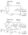
- FIG. 1 which represents the prior art that forms the starting point of the present invention
- the gas to be provided with water vapor is supplied at 2 to a gas humidifier 1 in the lower region.
- the gas enriched with water vapor leaves the gas humidifier at 3 at the top.
- Heated water is entered at 4 in the gas humidifier 1 and drawn off at 5 in the bottom of the sump, the amount of hot water sprayed in being greater than the amount withdrawn from the sump by the the gas has been enriched with water vapor.
- the heated hot water is then sprayed back into the gas humidifier 1 at 4 from the heat exchanger 7.
- the heat exchanger 7 is z. B. heated by a heat flow, such as a hot synthesis gas stream from a methanol reactor, which is indicated by the feed line 9 to the heat exchanger and the discharge line 10 with the corresponding arrows.
- the gas humidifier is basically divided into two areas; into an upper area 11 and a lower area 12.
- the upper area 11 the total amount of hot process water used is sprayed in at 4 'and acts on the total amount of the exiting gas stream which acts on the gas humidifier at 2' below and at 3 'with water vapor leaves freighted.
- the division between 11 and 12 is indicated by a dashed line 13 in the gas humidifier 1 '.
- a subset of the process water is drawn off at 14.
- the remaining amount still acts on the lower area 12 of the gas humidifier 1 'and exits at 5' in the sump.
- the first partial quantity emerging at 14 has a higher temperature than the second partial quantity or residual quantity emerging from the sump, the first partial quantity in the exemplary embodiment being intended to be larger than the remaining quantity, which is due to the different proportions of the regions 11 and 12 of the gas humidifier 1 'is indicated.
- the first subset, which leaves the gas humidifier 1 'at 14, is fed via a pump 6, a heat exchanger 7', which from the hot side of a heat flow, for. B. a synthesis gas from a methanol reactor, which in turn is indicated by an arrow line 9 '.
- the second subset leaving the sump is fed via a pump to a second heat exchanger 15, which is in the heat flow 9'-10 'on the colder side, ie. H. downstream, as shown in FIG. 2.
- This partial flow or residual flow is heated to such an extent that it has approximately the same temperature as the first partial flow leaving the gas humidifier at 14.
- the two subsets are then combined at 16 and fed to the last heat exchanger in this circuit 7 '.
- Fig. 3 shows another embodiment again with the same reference numerals for basically the same system parts. The difference is that in addition to the final heating stage through the heat exchanger 7 "in the same heat flow 9 '' 10 '', in addition to the heat exchanger 15, a further heat exchanger 17 is provided, the flow guidance of the partial quantities being basically the same here as in the example in FIG. 2, ie the coldest partial amount or residual amount from the sump 5 ", the make-up water is fed in at 8", these amounts are passed through the first preheater 15 and then fed to the further heat exchanger 17 together with a partial amount leaving the gas humidifier at 18 in order to continue there Together with the first partial amount leaving the gas humidifier 1 ′′ at 19, the total amount of water in the final heating stage, i. H. the heat exchanger 7 ".
Landscapes
- Chemical & Material Sciences (AREA)
- Organic Chemistry (AREA)
- Chemical Kinetics & Catalysis (AREA)
- Hydrogen, Water And Hydrids (AREA)
- Organic Low-Molecular-Weight Compounds And Preparation Thereof (AREA)
- Air Humidification (AREA)
- Gas Separation By Absorption (AREA)
- Emulsifying, Dispersing, Foam-Producing Or Wetting Agents (AREA)
- Investigating Or Analyzing Materials By The Use Of Fluid Adsorption Or Reactions (AREA)
- Treating Waste Gases (AREA)
- Disinfection, Sterilisation Or Deodorisation Of Air (AREA)
- Exhaust Gas Treatment By Means Of Catalyst (AREA)
- Solid-Sorbent Or Filter-Aiding Compositions (AREA)
Abstract
Description
Die Erfindung richtet sich auf ein Verfahren zum Befeuchten eines Gasstromes, bei dem aufgeheiztes Wasser zur Abgabe von Wasserdampf im Gegenstrom zum Gasstrom durch einen Gasbefeuchter und anschließend nach Einspeisung von der Menge des abgegebenen Wasserdampfes entsprechendem Zusatzwasser einer Aufheizstufe und zurück zum Gasbefeuchter im Kreislauf geführt wird.The invention is directed to a method for humidifying a gas stream, in which heated water for delivering water vapor in countercurrent to the gas stream is passed through a gas humidifier and then, after feeding in the corresponding make-up water from the amount of water vapor emitted, and back to the gas humidifier in the circuit.
Ein derartiges Verfahren ist bekannt. Dieses Verfahren wird z. B. bei der Erdgasaufbereitung eingesetzt. Bei derartigen katalytischen Prozessen ist es manchmal nötig, ein bestimmtes Wasserdampf-/Gasverhältnis zu erreichen, was beim Stand der Technik durch ein Verfahren der eingangs bezeichneten Art erreicht wird, wobei die Aufnahme von Wasserdampf dort nicht ausreichend genug ist, so daß energetisch hochwertiger Dampf in den Gasstrom nach Verlassen des Gasbefeuchters noch zusätzlich eingespeist werden muß.Such a method is known. This method is e.g. B. used in natural gas processing. In such catalytic processes it is sometimes necessary to achieve a certain water vapor / gas ratio, which is achieved in the prior art by a method of the type mentioned at the outset, the absorption of water vapor being insufficient there, so that energetically high-quality steam in the gas flow must be additionally fed in after leaving the gas humidifier.
Aufgabe der Erfindung ist die Schaffung einer Lösung, mit der eine Gasbefeuchtung vorgenommen werden kann, deren Wasseraufnahme besonders hoch ist und den späteren Einsatzbedingungen möglichst nahekommt, gleichzeitig aber qualitativ mindere Energie, insbesondere Energie auf niedrigem Temperaturniveau, ausgenutzt werden kann.The object of the invention is to provide a solution with which a gas humidification can be carried out, the water absorption of which is particularly high and comes as close as possible to the later operating conditions, but at the same time lower quality energy, in particular energy at a low temperature level, can be used.
Mit einem Verfahren der eingangs bezeichneten Art wird diese Aufgabe gemäß der Erfindung dadurch gelöst, daß Teilmengen des Kreislauf- wassers in mehreren, hintereinanderliegenden Stufen dem Gasbefeuchter entnommen und die einzelnen Teilmengen einzeln und/oder gemeinsam erhitzt bzw. erwärmt werden.With a method of the type mentioned at the outset, this object is achieved according to the invention in that partial quantities of the circulating water are removed from the gas humidifier in several stages one behind the other and the individual partial quantities are heated or heated individually and / or together.
Durch die Erfindung wird erreicht, daß nicht mehr der Gesamtwasserstrom von der den Gasbefeuchter verlassenden niedrigen Temperatur auf die höhere Eintrittstemperatur erhitzt zu werden braucht, sondern hierfür eine Stufenerhitzung einzelner Teilströme nutzbar gemacht werden kann.It is achieved by the invention that the total water flow no longer needs to be heated from the low temperature leaving the gas humidifier to the higher inlet temperature, but instead a step heating of individual partial flows can be used.
In Ausgestaltung sieht die Erfindung vor, daß das Kreislaufwasser in zwei Stufen dem Gasbefeuchter entnommen wird, wobei die erste entnommene Teilmenge größer ist als die zweite Teilmenge. Grundsätzlich könnten auch andere Mengenverhältnisse, etwa gleich große Teilströme, vorgesehen sein, allerdings ist die erfindungsgemäße Aufteilung der Teilmengen besonders zweckmäßig.In an embodiment, the invention provides that the circulating water is removed from the gas humidifier in two stages, the first partial quantity removed being greater than the second partial quantity. In principle, other quantitative ratios, for example partial flows of the same size, could also be provided, but the division of the partial quantities according to the invention is particularly expedient.
Vorteilhaft ist es, wenn, wie dies die Erfindung ebenfalls vorsieht, die zweite Teilmenge einer Vorwärmstufe und anschließend zusammen mit der ersten Teilmenge einer Endheizstufe zugeführt wird. DieseVerfahrensweise ermöglicht es, die entsprechenden Vorwärm- bzw. Endheizstufen in günstigen Temperatur-Bereichen auslegen zu können, so daß bereits geringere Temperaturdifferenzen ausreichen, die Durchsatzmengen zu erwärmen.It is advantageous if, as is also provided by the invention, the second subset is fed to a preheating stage and then together with the first subset to a final heating stage. This procedure makes it possible to design the appropriate preheating or final heating stages in favorable temperature ranges, so that even smaller temperature differences are sufficient to heat the throughput quantities.
In weiterer Ausgestaltung ist nach der Erfindung vorgesehen, daß der letzten aus dem Gasbefeuchter entnommenen Teilmenge die Zusatzwassermenge vor der ersten Vorwärmstufe zugeführt wird.In a further embodiment it is provided according to the invention that the make-up water quantity is supplied to the last partial quantity removed from the gas humidifier before the first preheating stage.
Um besonders Abfallwärme, z. B. die Synthesegaswärme, aus einem Methanolreaktor zum Erwärmen des Kreislaufwassers optimal ausnützen zu können, ist nach der Erfindung vorgesehen, daß die Vorwärmstufe oder -stufen und die Endheizstufe als Wärmetauscher für heißes Synthesegas hintereinander in einen gemeinsamen Wärmestrom geschaltet sind, wobei in weiterer Ausgestaltung vorgesehen sein kann, daß die Teilmenge aus den vorangehenden, stromabwärts bezogen auf den Wärmestrom liegenden Wärmetauscher zusammen mit einer Teilmenge aus dem Gasbefeuchter den nächsten stromaufwärts liegenden Wärmetauscher zugeführt wird.To especially waste heat, e.g. B. the synthesis gas heat from a methanol reactor for heating the circulating water can be optimally used according to the invention that the preheating stage or stages and the final heating stage are connected in series as a heat exchanger for hot synthesis gas in a common heat flow, provided in a further embodiment may be that the partial quantity from the preceding heat exchangers located downstream in relation to the heat flow is fed together with a partial quantity from the gas humidifier to the next upstream heat exchanger.
Diese Ausgestaltungen der erfindungsgemäßen Verfahrensweise sind besonders zweckmäßig, da die entsprechend eingesetzten, dem Wärmestrom ausgesetzten Wärmetauscher sehr günstig ausgelegt werden können, so daß z. B. die Restwassermenge aus dem Sumpf des Gasbefeuchters dem am weitesten stromabwärts liegenden Wärmetauscher, d. h. dem kältesten Wärmetauscher, zur ersten Vorheizung zugeführt wird, sodann wird die an vorletzter Stelle entnommene Teilmenge von aufzuwärmendem Wasser aus dem Gasbefeuchter zusammen mit der der ersten Vorwärmung unterzogenen Restmenge dem nächsten Wärmetauscher zugeführt. Die Einrichtung wird dann zweckmäßig so getroffen, daß jeweils die aus einer Stufe des Gasbefeuchters entnommene Teilmenge im gleichen Temperaturbereich liegt, wie die dem vorangegangenen Vorwärmer verlassende und dieserTeilmenge zugemischte andere Teilmenge.These embodiments of the procedure according to the invention are particularly expedient, since the heat exchangers which are used accordingly and which are exposed to the heat flow can be designed very cheaply, so that, for. B. the amount of residual water from the bottom of the gas humidifier the most downstream heat exchanger, d. H. is fed to the coldest heat exchanger for the first preheating, then the partial amount of water to be heated removed from the gas humidifier at the penultimate point is fed to the next heat exchanger together with the remaining amount subjected to the first preheating. The device is then expediently made such that the portion removed from a stage of the gas humidifier is in the same temperature range as the other portion leaving the previous preheater and mixed with this portion.
Die Erfindung ist nachstehend anhand der Zeichnung näher beschrieben. Dabei zeigt
- Fig. 1 ein Prinzipschaltbild nach dem Stand der Technik,
- Fig. 2 ein Prinzipschaltbild nach einem Ausführungsbeispiel der Erfindung und
- Fig. 3 ein weiteres Ausführungsbeispiel der Erfindung.
- 1 is a block diagram according to the prior art,
- Fig. 2 is a block diagram according to an embodiment of the invention and
- Fig. 3 shows another embodiment of the invention.
In Fig. 1, die den Stand der Technik, der Ausgangspunkt der vorliegenden Erfindung bildet, darstellt, wird einem Gasbefeuchter 1 im unteren Bereich das mit Wasserdampf zu versehene Gas bei 2 zugeführt. Das mit Wasserdampf angereicherte Gas verläßt oben den Gasbefeuchter bei 3. Aufgeheiztes Wasser wird oben in dem Gasbefeuchter 1 bei 4 eingegeben und unten im Sumpf bei 5 abgezogen, wobei die eingesprühte Heißwassermenge um den Betrag größer ist, als die aus dem Sumpf abgezogene, um den das Gas mit Wasserdampf angereichert worden ist. Das durch den Gasgegenstrom abgekühlte im Sumpf gesammelte Wasser 5 wird über eine Pumpe 6 einem Wärmetauscher 7 zugeführt, wobei vor dem Wärmetauscher 7 bei 8 eine Menge an Zusatzwass;er in den Kreislauf eingespeist wird, die der Menge des vom Gas aufgenommenen Wasserdampfes entspricht. Vom Wärmetauscher 7 wird dann das erhitzte Heißwasser wieder bei 4 in den Gasbefeuchter 1 eingesprüht. Der Wärmetauscher 7 wird z. B. von einem Wärmestrom, etwa einem heißen Synthesegasstrom aus einem Methanolreaktor beheizt, was durch die Zuleitung 9 zum Wärmetauscher und die Ableitung 10 mit den entsprechenden Pfeilen angedeutet ist.In FIG. 1, which represents the prior art that forms the starting point of the present invention, the gas to be provided with water vapor is supplied at 2 to a
Bei der Beschreibung der Erfindung nach den Fig. 2 und 3 werden die dem Prinzip nach gleichen Anlageelemente mit gleichen Bezugsziffern bezeichnet. Zur besseren Identifizierung allerdings einfach bzw. zweifach gestrichen. Dies bedeutet z. B., daß der Gasbefeuchter in Fig. 2 mit dem Bezugszeichen 1' bezeichnet ist, der Gasbefeuchter in Fig. 3 mit dem Bezugszeichen 1".In the description of the invention according to FIGS. 2 and 3, the principle of the same system elements with the same reference numerals. For better identification, however, deleted one or two times. This means e.g. B. that the gas humidifier in Fig. 2 is denoted by the reference numeral 1 ', the gas humidifier in Fig. 3 by the
Wie sich bei dem Ausführungsbeispiel aus Fig. 2 ergibt, ist dort der Gasbefeuchter prinzipiell in zwei Bereiche eingeteilt; in einen oberen Bereich 11 und einen unteren Bereich 12. In dem oberen Bereich 11 wird die Gesamtmenge des heißen eingesetzten Prozeßwassers bei 4' eingesprüht und beaufschlagt die Gesamtmenge des austretenden Gasstromes, der unten bei 2' den Gasbefeuchter beaufschlagt und oben bei 3' mit Wasserdampf befrachtet verläßt.As can be seen in the exemplary embodiment from FIG. 2, there the gas humidifier is basically divided into two areas; into an
Durch eine gestrichelt wiedergegebene Trennlinie 13 im Gasbefeuchter 1' ist die Bereichstrennung zwischen 11 und 12 angedeutet. An dieser Stelle wird eine Teilmenge des Prozeßwassers bei 14 abgezogen. Die Restmenge beaufschlagt noch den unteren Bereich 12 des Gasbefeuchters 1' und tritt im Sumpf bei 5' aus. Die bei 14 ausgetretene, erste Teilmenge weist eine höhere Temperatur auf als die aus dem Sumpf austretende zweite Teilmenge bzw. Restmenge, wobei die erste Teilmenge beim Ausführungsbeispiel größer sein soll als die Restmenge, was durch die unterschiedlichen Proportionen der Bereiche 11 und 12 des Gasbefeuchters 1' angedeutet ist.The division between 11 and 12 is indicated by a
Die erste Teilmenge, die bei 14 den Gasbefeuchter 1' verläßt, wird über eine Pumpe 6, einem Wärmetauscher 7' zugeführt, der von der heißen Seite eines Wärmestromes, z. B. eines Synthesegases aus einem Methanolreaktor beaufschlagt wird, was wiederum durch eine Pfeillinie 9' angedeutet ist.The first subset, which leaves the gas humidifier 1 'at 14, is fed via a
Die den Sumpf verlassende zweite Teilmenge wird über eine Pumpe einem zweiten Wärmetauscher 15 zugeleitet, der im Wärmestrom 9'-10' auf der kälteren Seite, d. h. stromabwärts, angeordnet ist, wie sich dies aus Fig. 2 ergibt. Dabei wird dieser Teilstrom bzw. Reststrom so stark erwärmt, daß er etwa die gleiche Temperatur aufweist, wie der bei 14 den Gasbefeuchter verlassende erste Teilstrom. Die beiden Teilmengen werden dann bei 16 vereinigt und dem letzten Wärmetauscher in diesem Kreislauf 7' zugeführt.The second subset leaving the sump is fed via a pump to a
Aus Fig. 2 ergibt sich auch, daß das Zusatzwasser über 8' der zweiten Teilmenge bzw. der Restmenge zugespeist wird und damit der ersten Vorwärmung über den Wärmetauscher 15 mit unterworfen wird.2 also shows that the make-up water is fed in via 8 'of the second partial amount or the remaining amount and is therefore also subjected to the first preheating via the
Fig. 3 zeigt ein weiteres Ausführungsbeispiel wiederum mit gleichen Bezugszeichen für prinzipiell gleiche Anlageteile. Der Unterschied besteht darin, daß neben der Enderhitzungsstufe durch den Wärmetauscher 7" im gleichen Wärmestrom 9'' 10'' zusätzlich zum Wärmetauscher 15 ein weiterer Wärmetauscher 17 vorgesehen ist, wobei hier prinzipiell die Strömungsführung der Teilmengen die gleiche ist wie beim Beispiel der Fig. 2, d. h. der kältesten Teilmenge bzw. Restmenge aus dem Sumpf 5", wird bei 8" das Zusatzwasser zugespeist, diese Mengen über den ersten Vorwärmer 15 geleitet und dann zusammen mit einer bei 18 den Gasbefeuchterverlassenden Teilmenge dem weiteren Wärmetauscher 17 zugeleitet, um dort weiter vorgewärmt zu werden. Zusammen mit der bei 19 den Gasbefeuchter 1" verlassenden ersten Teilmenge wird die Gesamtwassermenge der Endheizstufe, d. h. dem Wärmetauscher7", zugeführt.Fig. 3 shows another embodiment again with the same reference numerals for basically the same system parts. The difference is that in addition to the final heating stage through the
Natürlich sind die beschriebenen Ausführungsbeispiele noch in vielfacher Hinsicht abzuändern, ohne den Grundgedanken der Erfindung zu verlassen. So ist die Erfindung insbesondere nicht auf besondere bauliche Gestaltungen der im Verfahren eingesetzten Anlageteile beschränkt, auch nicht auf die in den Figuren wiedergegebene Prozeßführung. In der Bauart können auch Aggregate parallel statt hintereinander angeordnet sein u. dgl. mehr.Of course, the exemplary embodiments described can be modified in many ways without departing from the basic idea of the invention. Thus, the invention is in particular not restricted to special structural designs of the plant parts used in the method, nor to the process control shown in the figures. In design, units can also be arranged in parallel instead of one behind the other u. Like. more.
Claims (6)
Priority Applications (1)
| Application Number | Priority Date | Filing Date | Title |
|---|---|---|---|
| AT83106036T ATE14993T1 (en) | 1982-10-01 | 1983-06-21 | PROCESS FOR HUMIDIFICATION OF A GAS STREAM, ESPECIALLY FOR METHANOL AND/OR AMMONIA PLANTS. |
Applications Claiming Priority (2)
| Application Number | Priority Date | Filing Date | Title |
|---|---|---|---|
| DE3236441A DE3236441C2 (en) | 1982-10-01 | 1982-10-01 | Method for humidifying a gas stream, in particular for methanol and / or ammonia plants |
| DE3236441 | 1982-10-01 |
Publications (2)
| Publication Number | Publication Date |
|---|---|
| EP0105089A1 EP0105089A1 (en) | 1984-04-11 |
| EP0105089B1 true EP0105089B1 (en) | 1985-08-21 |
Family
ID=6174718
Family Applications (1)
| Application Number | Title | Priority Date | Filing Date |
|---|---|---|---|
| EP83106036A Expired EP0105089B1 (en) | 1982-10-01 | 1983-06-21 | Process for moistening a gas stream, especially for methanol and/or ammonia producing plants |
Country Status (10)
| Country | Link |
|---|---|
| US (1) | US4528147A (en) |
| EP (1) | EP0105089B1 (en) |
| JP (1) | JPS5982933A (en) |
| AT (1) | ATE14993T1 (en) |
| AU (1) | AU560847B2 (en) |
| CA (1) | CA1209029A (en) |
| DE (2) | DE3236441C2 (en) |
| DK (1) | DK156266C (en) |
| NO (1) | NO160332C (en) |
| SU (1) | SU1309903A3 (en) |
Families Citing this family (3)
| Publication number | Priority date | Publication date | Assignee | Title |
|---|---|---|---|---|
| DE102005034175A1 (en) * | 2005-07-21 | 2007-01-25 | Roche Diagnostics Gmbh | Method and device for generating a moist air flow with defined relative humidity |
| US9327249B2 (en) | 2012-04-17 | 2016-05-03 | Air Products And Chemicals, Inc. | Systems and methods for humidifying gas streams |
| CN115121191B (en) * | 2022-07-13 | 2023-08-04 | 重庆大学 | And (3) preparing PEDOT by gas-liquid two-phase reaction: PSS device and method |
Family Cites Families (10)
| Publication number | Priority date | Publication date | Assignee | Title |
|---|---|---|---|---|
| US476274A (en) * | 1892-06-07 | Apparatus for purifying | ||
| US1986529A (en) * | 1931-05-27 | 1935-01-01 | William W Varney | Conditioning liquids and air and other gases |
| US2220219A (en) * | 1937-11-17 | 1940-11-05 | Robert B P Crawford | Regenerative cooling system |
| US2826397A (en) * | 1952-03-27 | 1958-03-11 | Svenska Flaektfabriken Ab | Scrubbers |
| DE1253679B (en) * | 1963-01-24 | 1967-11-09 | Metallgesellschaft Ag | Device for the continuous implementation of chemical reactions and physico-chemical processes between liquid and gaseous substances |
| US3249152A (en) * | 1964-01-02 | 1966-05-03 | Monsanto Co | Heat recovery process |
| SE308657B (en) * | 1965-06-02 | 1969-02-17 | Mo Och Domsjoe Ab | |
| DE2335659C2 (en) * | 1973-07-13 | 1982-10-28 | Krupp-Koppers Gmbh, 4300 Essen | Process for generating a methane-containing gas |
| US3927153A (en) * | 1973-08-14 | 1975-12-16 | Bethlehem Steel Corp | Process for direct cooling of corrosive industrial cases |
| US4276243A (en) * | 1978-12-08 | 1981-06-30 | Western Electric Company, Inc. | Vapor delivery control system and method |
-
1982
- 1982-10-01 DE DE3236441A patent/DE3236441C2/en not_active Expired
-
1983
- 1983-06-21 EP EP83106036A patent/EP0105089B1/en not_active Expired
- 1983-06-21 AT AT83106036T patent/ATE14993T1/en not_active IP Right Cessation
- 1983-06-21 DE DE8383106036T patent/DE3360610D1/en not_active Expired
- 1983-06-30 NO NO832391A patent/NO160332C/en unknown
- 1983-08-26 AU AU18452/83A patent/AU560847B2/en not_active Ceased
- 1983-09-26 CA CA000437539A patent/CA1209029A/en not_active Expired
- 1983-09-29 JP JP58179487A patent/JPS5982933A/en active Pending
- 1983-09-29 SU SU833648850A patent/SU1309903A3/en active
- 1983-09-30 US US06/537,636 patent/US4528147A/en not_active Expired - Fee Related
- 1983-09-30 DK DK453983A patent/DK156266C/en not_active IP Right Cessation
Also Published As
| Publication number | Publication date |
|---|---|
| NO832391L (en) | 1984-04-02 |
| DE3236441C2 (en) | 1985-09-19 |
| ATE14993T1 (en) | 1985-09-15 |
| CA1209029A (en) | 1986-08-05 |
| DE3236441A1 (en) | 1984-04-05 |
| NO160332B (en) | 1989-01-02 |
| EP0105089A1 (en) | 1984-04-11 |
| DK156266B (en) | 1989-07-24 |
| US4528147A (en) | 1985-07-09 |
| AU1845283A (en) | 1984-04-05 |
| DE3360610D1 (en) | 1985-09-26 |
| DK453983A (en) | 1984-04-02 |
| DK156266C (en) | 1989-12-18 |
| DK453983D0 (en) | 1983-09-30 |
| JPS5982933A (en) | 1984-05-14 |
| AU560847B2 (en) | 1987-04-16 |
| NO160332C (en) | 1989-04-12 |
| SU1309903A3 (en) | 1987-05-07 |
Similar Documents
| Publication | Publication Date | Title |
|---|---|---|
| EP1009920A1 (en) | Steam generator, especially waste heat recovery steam generator and method for operating said generator | |
| DE10330859A1 (en) | Operating emission-free gas turbine power plant involves feeding some compressed circulated gas directly to combustion chamber, cooling/humidifying some gas before feeding to combustion chamber | |
| DE3035349C2 (en) | Plant for the evaporation of liquid natural gas | |
| AT394100B (en) | HEAT STEAM GENERATOR | |
| DE2951557C2 (en) | Method for operating a thermal material separation process with integrated heat recovery and device for carrying out the method | |
| DE3028913A1 (en) | METHOD FOR PREHEATING AIR | |
| DE2263319A1 (en) | PROCESS AND DEVICE FOR THE REDUCTION OF THE WATER VAPOR CONTENT IN THE AIR | |
| DE2648219A1 (en) | PROCESS FOR HEATING A STREAMING MEDIUM IN A PLANT FOR EVAPORATING AND DRYING A PRODUCT | |
| DE3834716A1 (en) | METHOD AND DEVICE FOR CONCENTRATING SOLUTIONS | |
| EP0105089B1 (en) | Process for moistening a gas stream, especially for methanol and/or ammonia producing plants | |
| DE2614587A1 (en) | PROCEDURE FOR EVAPORATING WATER-BASED LIQUIDS | |
| DE2632910A1 (en) | Concentrating radioactive effluent by multistage evaporation - with liq. inlet at late stage and condensate recycling to earlier stages | |
| DE69520366T2 (en) | METHOD FOR FINAL EVAPORATION OF BLACK LYE | |
| AT395831B (en) | METHOD AND DEVICE FOR CATALYTICALLY REDUCING POLLUTANTS IN SMOKE GAS | |
| EP0019297A2 (en) | Method and device for steam generation | |
| AT397305B (en) | METHOD FOR DRYING A LONG-STRETCHED GOODS MOVED IN THE LONGITUDINAL DIRECTION, AND ARRANGEMENT FOR IMPLEMENTING THE METHOD | |
| DE752321C (en) | Process for separating water from gases containing nitrogen oxide | |
| DE973504C (en) | Device for the precipitation of excess steam in steam power plants | |
| DE19524216A1 (en) | Apparatus for preheating and degasifying water by steam in steam power plants - has mixing preheaters in series on water side with last preheater mounted on supply water container and pump in front of each preheater | |
| DE3609705C2 (en) | ||
| CH635165A5 (en) | INDUSTRIAL STEAM TURBINE SYSTEM. | |
| DE19703468C2 (en) | Steam power plant | |
| DE2830514C2 (en) | Multi-stage flash evaporator | |
| DE1444352A1 (en) | Evaporation system with downdraft heaters | |
| DE2701728C3 (en) | Process for cooling gases with heat exchangers |
Legal Events
| Date | Code | Title | Description |
|---|---|---|---|
| PUAI | Public reference made under article 153(3) epc to a published international application that has entered the european phase |
Free format text: ORIGINAL CODE: 0009012 |
|
| 17P | Request for examination filed |
Effective date: 19840113 |
|
| AK | Designated contracting states |
Designated state(s): AT DE FR GB IT NL SE |
|
| ITF | It: translation for a ep patent filed | ||
| GRAA | (expected) grant |
Free format text: ORIGINAL CODE: 0009210 |
|
| AK | Designated contracting states |
Designated state(s): AT DE FR GB IT NL SE |
|
| REF | Corresponds to: |
Ref document number: 14993 Country of ref document: AT Date of ref document: 19850915 Kind code of ref document: T |
|
| REF | Corresponds to: |
Ref document number: 3360610 Country of ref document: DE Date of ref document: 19850926 |
|
| ET | Fr: translation filed | ||
| PLBE | No opposition filed within time limit |
Free format text: ORIGINAL CODE: 0009261 |
|
| STAA | Information on the status of an ep patent application or granted ep patent |
Free format text: STATUS: NO OPPOSITION FILED WITHIN TIME LIMIT |
|
| 26N | No opposition filed | ||
| PGFP | Annual fee paid to national office [announced via postgrant information from national office to epo] |
Ref country code: SE Payment date: 19900528 Year of fee payment: 8 |
|
| PG25 | Lapsed in a contracting state [announced via postgrant information from national office to epo] |
Ref country code: SE Effective date: 19910622 |
|
| ITTA | It: last paid annual fee | ||
| PGFP | Annual fee paid to national office [announced via postgrant information from national office to epo] |
Ref country code: DE Payment date: 19920502 Year of fee payment: 10 |
|
| PGFP | Annual fee paid to national office [announced via postgrant information from national office to epo] |
Ref country code: GB Payment date: 19920508 Year of fee payment: 10 |
|
| PGFP | Annual fee paid to national office [announced via postgrant information from national office to epo] |
Ref country code: FR Payment date: 19920521 Year of fee payment: 10 |
|
| PGFP | Annual fee paid to national office [announced via postgrant information from national office to epo] |
Ref country code: AT Payment date: 19920625 Year of fee payment: 10 |
|
| PGFP | Annual fee paid to national office [announced via postgrant information from national office to epo] |
Ref country code: NL Payment date: 19920630 Year of fee payment: 10 |
|
| PG25 | Lapsed in a contracting state [announced via postgrant information from national office to epo] |
Ref country code: GB Effective date: 19930621 Ref country code: AT Effective date: 19930621 |
|
| PG25 | Lapsed in a contracting state [announced via postgrant information from national office to epo] |
Ref country code: NL Effective date: 19940101 |
|
| GBPC | Gb: european patent ceased through non-payment of renewal fee |
Effective date: 19930621 |
|
| NLV4 | Nl: lapsed or anulled due to non-payment of the annual fee | ||
| PG25 | Lapsed in a contracting state [announced via postgrant information from national office to epo] |
Ref country code: FR Effective date: 19940228 |
|
| PG25 | Lapsed in a contracting state [announced via postgrant information from national office to epo] |
Ref country code: DE Effective date: 19940301 |
|
| REG | Reference to a national code |
Ref country code: FR Ref legal event code: ST |
|
| EUG | Se: european patent has lapsed |
Ref document number: 83106036.3 Effective date: 19920109 |