EP0104803B1 - Marking apparatus - Google Patents
Marking apparatus Download PDFInfo
- Publication number
- EP0104803B1 EP0104803B1 EP83305100A EP83305100A EP0104803B1 EP 0104803 B1 EP0104803 B1 EP 0104803B1 EP 83305100 A EP83305100 A EP 83305100A EP 83305100 A EP83305100 A EP 83305100A EP 0104803 B1 EP0104803 B1 EP 0104803B1
- Authority
- EP
- European Patent Office
- Prior art keywords
- tubing
- marking
- instrument
- indicia
- head
- Prior art date
- Legal status (The legal status is an assumption and is not a legal conclusion. Google has not performed a legal analysis and makes no representation as to the accuracy of the status listed.)
- Expired
Links
Images

Classifications
-
- H—ELECTRICITY
- H01—ELECTRIC ELEMENTS
- H01B—CABLES; CONDUCTORS; INSULATORS; SELECTION OF MATERIALS FOR THEIR CONDUCTIVE, INSULATING OR DIELECTRIC PROPERTIES
- H01B13/00—Apparatus or processes specially adapted for manufacturing conductors or cables
- H01B13/34—Apparatus or processes specially adapted for manufacturing conductors or cables for marking conductors or cables
- H01B13/344—Apparatus or processes specially adapted for manufacturing conductors or cables for marking conductors or cables by applying sleeves, ferrules, tags, clips, labels or short length strips
Definitions
- the tubing is in contact with the rim of the roller over an arc subtending an acute angle at the roller axis, and the effect of the tubing being curved around the roller whilst being maintained under lengthwise tension is that the tubing is flattened at the location of pen 30, to present a flat area of maximum width to the pen.
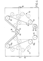
- Figure 4 shows the drive arrangements to the driven pulleys 47, 51 and 47a, 51a of the two drawing systems 42 and 43.
- a first electric servo motor is coupled to a drive shaft 60 on the same axis as roller 41 and carrying a toothed drive pulley 61 for a belt 62 which is correspondingly toothed on both its sides.
- Belt 62 is trained, as shown, under drive pulley 61, then around pulleys 63, 64, 65 and 63a whilst also engaging (on its outer side) pulleys 66 and 66a.
- a second electric servo motor is coupled to a drive shaft 67 of pulley 64, and the position of pulley 65 is manually adjustable to preset the belt tension.
Abstract
Description
- The present invention relates to a marking apparatus, having particular application to the provision of indicia on sleeves intended as markers for cables. The invention also relates to a method of producing individual marker sleeves.
- Markers are often used on electrical cables for identification purposes and conveniently may comprise a plastic sleeve, itself marked with the identifying indicia, slipped over the cable or wire to be marked.
- GB-A-1 536 178 discloses a marking apparatus comprising means for receiving tubing and transporting it lengthwise of itself past a marking head of the apparatus, means for generating electrical command signals defining successive indicia which are required to be marked on the tubing, the marking head being responsive to the electrical command signals to mark the tubing with the successive required indicia at successive locations along its length, and severing means responsive to further electrical command signals from the signal generating means to divide the tubing into desired lengths defining individual marker sleeves.
- The apparatus of GB-A-1 536 178 is primarily directed to printing indicia on a continuous elongate three-dimensional member such as a bundle of insulated wires, and provides a marking head of a particular type suited to printing on a surface having the pronounced transverse curvature of such a bundle. This marking head comprises an ink jet printer which discharges a jet of charged ink drops which are electrostatically deflected and the characters are marked on the surface as a discontinuous series of dots. The apparatus provides for severing the bundle of wires upstream of the marking head and then pushing the bundle past the marking head: this renders the apparatus unworkable when receiving plastics tubing and cutting this into the very short lengths required for marker sleeves.
- The apparatus of the present apparatus is characterised in that the severing means (70, 77, 78) is disposed downstream of the marking head (30) and means (41) are provided for temporarily flattening the tubing (16) transversely thereof at the location of the marking head so that the tubing is presented to the marking head in a transversely flattened condition.
- Severing the tubing downstream of the marking head simplifies the requirements for the transporting means which transports the tubing through the apparatus, and marker sleeves can be cut to very short lengths if desired. By temporarily flattening the tubing transversely of itself and presenting it to the marking head in this flattened condition, an area of maximum width of the tubing is presented to the marking head. This enables a marking pen or like instrument to be employed, which can then trace out a continuous line on the flat surface of the tubing, to form a character of considerably improved quality, as compared to the apparatus of GB-A-1 536 178.
- DE-B-1 015 016 discloses a manually- operated stamping machine for marking tubing and at the same time cutting the tubing downstream of the stamping head. The indicia to be marked are selected by hand and the tubing is advanced by hand and, although the tubing is flattened by the stamping head upon operation of the latter, there are no separate means for flattening the tubing and presenting a flattened tubing to the marking head.
- US-A-4 095 084 discloses an apparatus for perforating a flattened tube at intervals using a laser, in order to produce an irrigation tube. The apparatus is not arranged to receive a rounded tubing and to temporarily flatten it, nor to mark a tubing with selected indicia.
- The apparatus of the present invention serves to rapidly and automatically provide marker sleeves bearing indicia meeting individual requirements. This particularly enables a rapid service to be provided to those who apply markers to cables, in that an order for specified sleeves with specified indicia can quickly be converted to machine instructions to which the apparatus automatically responds for marking sleeves according to the requirements so that the order can be quickly fulfilled.
- A further preferred feature is that the marking head comprises a pen or like instrument which is physically moved in accordance with the received command signals to trace out (i.e. write) the required indicia on the flattened tubing, using a quick-drying ink. The pen may be mounted for movement along mutually perpendicular X, Y and Z axes in accordance with its command instructions, the Z-axis being used for lift and positioning purposes and the tubing being stationary at the instant of writing each index mark and then stepped forward before the next index mark is applied. Instead, the pen may be mounted for movement along only the Y-axis (transverse to the tubing) in addition to the Z-axis, the X-axis relative movement being achieved by lengthwise movement of the tubing (forwards and backwards according to the appropriate X-axis command signals being supplied to the tubing transporting means). In place of the pen, the marking may be carried out by laser, ultra violet or infra red beam, by a hot needle or ink jet or other means controlled according to the X and Y axes to trace out the indicia on the tubing according to the requirements.
- An embodiment of the marking apparatus according to the invention will now be described, by way of example only, with reference to the accompanying drawings, in which:
- FIGURE 1 is a schematic diagram of a marking apparatus in accordance with this invention;
- FIGURE 2 is a diagrammatic view of a marking pen and portion of tubing to illustrate the principles of operation of the marking head of the apparatus;
- FIGURE 3 is a diagrammatic view of the transporting mechanism for the tubing, seen from one side to show the transporting of the tubing;
- FIGURE 4 is a diagrammatic view of the tubing transporting mechanism, seen from the opposite side to show the driving arrangements of the mechanism;
- FIGURE 5 is a diagrammatic view of the tube- sever or semi-sever mechanism of the apparatus; and
- FIGURE 6 is a diagram of a laser marking instrument which may be employed instead of the marking pen.
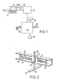
- Referring to Figure 1, the marking apparatus comprises a microprocessor-controlled
converter 10 for converting an incoming customer's order CO into machine instructions. The convertor includes a keyboard K or the like for manually formulating the machine instructions from the customer's order (which itself may be communicated in any form at all, whether written or verbal), together with a visual display unit VDU for checking and correcting purposes. The converter may also include provision for receiving the incoming order over a direct data link. The converter is arranged to issue stock control data, and also to collate similar orders: for example it may be arranged to collate from different orders requirements for sleeves of a like colour and size and to organise its machine instructions so that (within a batch of orders) these instructions relate firstly to all the requirements of one colour and size of sleeve, then to all the requirements of a second colour and size of sleeve, and so on. - The apparatus further comprises a machine instruction or
character generation unit 12 which generates the X, Y and X axis command signals (and tubing indexing command signals) from the infed machine instructions. Thus the generated command signals not only accord with the indicia or characters required to be marked on the sleeve, but also are arranged to control the stepping forward of the tubing (and the severing means) to control the spacing between the individual characters of each sleeve and the spacing of the indicia from the ends of the sleeve. In principle, the characters which may be marked are unlimited in form and thus may be alpha-numeric (of controlled size and format) or special devices if appropriate software for these is provided within the microprocessor system of themachine unit 12. - The apparatus further comprises a
marking unit 14 arranged to receive plastics tubing 16 (which may be heat-shrinkable) and transport this tubing lengthwise of itself through theunit 14, and past a marking head within the unit. The transporting mechanism of theunit 14 is arranged so that, at the position of the marking head, the tubing is under constant tension and is also flattened. The tubing may be stationary at the instant each character or index mark is written, the head including a marking pen which is driven along the X and Y axes in accordance with its command signals received from the machine instruction unit 12: alternatively, the X-axis command signal may be directed to the transporting mechanism to effect lengthwise (forwards and reverse) movement of the tubing past the writing pen, which itself only moves along the Y-axis (transverse to the tubing) in addition to the Z-axis movements in any event required for lift and positioning purposes. The marking unit further comprises a severing means for completely or partially severing the tubing as it issues from the marking unit: this severing means is synchronised to the stepping forwards of the tubing so that the severing is effected at the appropriate positions to define theindividual marker sleeves 18. - A
visual display unit 20 may be coupled to the marking unit for control purposes, to give a running check of the indicia currently being applied by the marking head and also to indicate when a change of tubing (e.g. colour or diameter) is required. An in-line printer 22 may also be provided to issue a print-out of the marks which have neen applied, to serve as a check list against the respective customer's order: preferably however aprinter 23 is coupled to theconverter 10 to provide a hard-copy print out of the orders being input into the apparatus. - Preferably an automatic packaging unit is provided to assemble and present the customer's order in either lengths of semi-severed sleeves in a required sequence and quantity, or as an assembly of separated sleeves again in the required sequence and quantity.
- Figure 2 shows the principles of operation of a marking head which comprises an
ink pen 30 mounted vertically above thetubing 16 and mounted for movement along the Y-axis transversely of the tubing whilst the X-axis movement, which is also necessary for each index mark or character, is produced by reciprocating thetubing 16 lengthwise of itself. Thepen 30 is mounted to acarriage 31 via asolenoid 32 which serves to lift the pen tip from the tubing and place it back in contact with the tubing according to requirements. Thecarriage 31 is mounted to atransverse beam 33 for sliding movement along the Y-axis and is coupled to abelt 34 which is trained aroundrollers 35 one of which is driven by an electric motor under the control of command signals to produce the Y-axis movement. - Figures 3 and 4 show the transporting mechanism for displacing the
tubing 16 lengthwise of itself past theink pen 30. The mechanism comprises ametal support plate 40 having fixed thereto shafts to which are journalled various rotary elements of the mechanism. Thetubing 16 is transported across one side ofplate 40, as shown in Figure 3, and passes over a freely-rotatable roller 41 which has its axis on the vertical axis of thepen 30.Roller 41 is profiled across its rim to constrain the tubing against transverse movement. The tubing is in contact with the rim of the roller over an arc subtending an acute angle at the roller axis, and the effect of the tubing being curved around the roller whilst being maintained under lengthwise tension is that the tubing is flattened at the location ofpen 30, to present a flat area of maximum width to the pen. - The transporting mechanism comprises two drawing systems for the tubing,
systems roller 41 and it is sufficient to describe indetail system 42, corresponding elements ofsystem 43 being given like reference numerals with the suffix a. Thus,system 42 comprises afirst belt 44 trained around twoidling pulleys pulley 47 which is spaced abovepulleys System 42 further comprises asecond belt 48 trained around twoidling pulleys pulley 51 spaced belowpulleys pulleys idling pulleys 45, 46 (i.e. pulley 45) lies intermediate the two loweridling pulleys idling pulleys 49, 50 (i.e. pulley 50) lies intermediate the twoidling pulleys pulley 50 projects beyond the imaginary line tangential to pulleys 45,46: accordingly, the tubing is gripped between the respective lengths ofbelts respective air cylinders jockey wheels idling pulleys tubing 16. - Figure 4 shows the drive arrangements to the driven
pulleys drawing systems roller 41 and carrying a toothed drive pulley 61 for abelt 62 which is correspondingly toothed on both its sides.Belt 62 is trained, as shown, under drive pulley 61, then aroundpulleys pulleys 66 and 66a. A second electric servo motor is coupled to adrive shaft 67 ofpulley 64, and the position ofpulley 65 is manually adjustable to preset the belt tension. Pulleys 63, 66 and 63a, 66a are coupled via unidirectional clutches to the drivenpulleys respective drawing systems - Operation of the transporting mechanism of Figures 3 and 4 is as follows. In order to index the
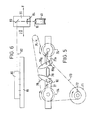
tubing 16 forwardly until an area to receive an index mark is immediately below thepen 30, the two drive motors are energised to drive pulley 61 counter-clockwise as viewed in Figure 4. In the consequent direction of movement of thebelt 62, pulleys 63 and 66 are rotated in the free-wheeling directions of their associated clutches, whilstpulleys pulleys system 43. The tubing is thus pulled forwardly bysystem 43 against a resistance imparted by virtue of the tortuous path of the tubing through the freewheelingsystem 42, thus appropriately tensioning the tubing. Once the tubing has been indexed forward in this manner to its required position for marking, the command signals from the character generation unit are applied to the pen carriage drive (for the Y-axis) and to the main and secondary drive motors coupled to pulleys 61 and 64 (for the X-axis). Thus during the character- marking, forward and backward displacement of the tubing (for the X-axis movement) is achieved by energising both drive motors forwards and backwards respectively. The drive sequence for forward displacement has just been described, whilst for backward displacement the drive topulley 64 displacesbelt 62 in the opposite direction.Pulleys pulleys 63, 66 are driven in their clutch engaging directions to transmit drive accordingly topulleys drawing system 42. The tubing is thus pulled backwards bysystem 42 against a resistance imparted by virtue of the tortuous path of the tubing through the freewheelingsystem 43. - Figure 5 shows the mechanism for severing or semi-severing the tubing, which mechanism is located- downstream of the transporting mechanism of Figures 3 and 4. The tubing passes to the severing or semi-severing mechanism through a guide comprising a length of
tube 70 of oval cross-section, serving to partially flatten the tubing to a correspondingly shaped cross-section. An electric servo motor 71 drives atoothed pulley 72 and a belt 73 (provided with teeth on both sides) is trained around drivepulley 72, around atoothed pulley 74 for a first cutter assembly, and around an idling pulley 75: the belt further engages atoothed pulley 76 for a second cutter assembly, the arrangement being that the two cutter assemblies are rotated simultaneously in opposite senses. The two cutter assemblies comprise radiatingarms respective pulleys cutting blades guide tube 70, which is oriented and aligned so that its oval cross-section is elongated along the plane containing the rotational axes of the two cutter assemblies. - The cutter assemblies are synchronised together so that, as shown, the blades fly simultaneously through the tubing at the two ends of its oval cross-section. The blades are inclined transversely to their
support arms screw - The energisation of the servo motor 71 is synchronised to operate the severing mechanism when the tubing is momentarily at rest, having been indexed to its appropriate position relative to the length of the individual, marked sleeve to be severed from the tubing.
- Where the marking pen is replaced by a laser, a steering mechanism for the laser may be provided as shown in Figure 6. The
tubing 16 is shown diagrammatically in its flattened condition overroller 41 at the marking location. Thelaser 80 is mounted to a fixed frame 81 of the apparatus, with itslaser beam 82 directed parallel to the Y-axis above the tubing. Thecarriage 31 of Figure 2 now mounts (in place of thepen 30 and solenoid 32) a mirror-and-lens assembly comprising firstly aplanar mirror 83 oriented at 45° to the Y and Z axes in order to direct the laser beam along the Z-axis, and secondly alens 84 to focus the beam onto the flat upper surface of the tubing. Thus, the Y-axis displacement of the point at which the laser beam strikes (and thereby marks) the tubing is achieved by Y-axis displacement of thecarriage 31, as described above in connection with Figure 2. - The apparatus which has been described with reference to Figures 2-6 has the advantages of a simple and reliable mechanism for producing the Y-axis displacement of the marking instrument, and a simple and reliable mechanism for producing the X-axis displacement of the tubing relative to the marking instrument, in both cases in response to the command signals from the character generation unit. Moreover the marking instrument itself is particularly simple, whilst the character generation unit can provide for a very wide range of types and styles of characters.
Claims (15)
Priority Applications (1)
| Application Number | Priority Date | Filing Date | Title |
|---|---|---|---|
| AT83305100T ATE34254T1 (en) | 1982-09-02 | 1983-09-02 | MARKING DEVICE. |
Applications Claiming Priority (2)
| Application Number | Priority Date | Filing Date | Title |
|---|---|---|---|
| GB8225055 | 1982-09-02 | ||
| GB8225055 | 1982-09-02 |
Publications (3)
| Publication Number | Publication Date |
|---|---|
| EP0104803A2 EP0104803A2 (en) | 1984-04-04 |
| EP0104803A3 EP0104803A3 (en) | 1985-11-13 |
| EP0104803B1 true EP0104803B1 (en) | 1988-05-11 |
Family
ID=10532650
Family Applications (1)
| Application Number | Title | Priority Date | Filing Date |
|---|---|---|---|
| EP83305100A Expired EP0104803B1 (en) | 1982-09-02 | 1983-09-02 | Marking apparatus |
Country Status (6)
| Country | Link |
|---|---|
| US (1) | US4534313A (en) |
| EP (1) | EP0104803B1 (en) |
| AT (1) | ATE34254T1 (en) |
| CA (1) | CA1210316A (en) |
| DE (1) | DE3376606D1 (en) |
| GB (1) | GB2126169B (en) |
Families Citing this family (48)
| Publication number | Priority date | Publication date | Assignee | Title |
|---|---|---|---|---|
| DE3416013C2 (en) * | 1984-04-30 | 1991-01-03 | Volker Dipl.-Ing. 3548 Arolsen Meywald | Method and device for the production of length measuring devices |
| US4655129A (en) * | 1985-10-11 | 1987-04-07 | W. H. Brady Co. | Marker sleeve processing machine |
| US4729305A (en) * | 1986-01-10 | 1988-03-08 | Alliance Rubber Company | Method and apparatus for making printed elastic bands |
| US5165336A (en) * | 1986-01-10 | 1992-11-24 | Alliance Rubber Company, Inc. | Method and apparatus for making printed elastic bands |
| US5113757A (en) * | 1986-01-10 | 1992-05-19 | Alliance Rubber Company, Inc. | Method and apparatus for making printed elastic bands |
| US4712120A (en) * | 1986-03-17 | 1987-12-08 | C-E Industrial Lasers, Incorporated | Laser materials treatment system |
| DE3721651A1 (en) * | 1987-07-01 | 1989-01-12 | Philips & Du Pont Optical | METHOD FOR PRINTING DISK-SHAPED INFORMATION CARRIERS |
| US4822987A (en) * | 1988-01-25 | 1989-04-18 | Westinghouse Electric Corp. | Method and apparatus for providing fuel rod identification to permit traceability during manufacture and use |
| US4906170A (en) * | 1988-02-16 | 1990-03-06 | Cello-O-Core | Apparatus for printing on plastic tubing |
| US5130721A (en) * | 1989-01-09 | 1992-07-14 | General Laser, Inc. | Laser wire marking method and apparatus |
| US5223852A (en) * | 1991-08-29 | 1993-06-29 | Northern Telecom Limited | Methods and apparatus for printing onto cable jacket |
| US5403398A (en) * | 1992-07-23 | 1995-04-04 | Riess; Robert | Mail tracker with zip break marker |
| US5766705A (en) * | 1995-10-10 | 1998-06-16 | Raychem Corporation | Marker sleeve assembly |
| US6019151A (en) * | 1997-01-07 | 2000-02-01 | Eastman Kodak Company | Printing onto discs such as compact discs and the like |
| US6264296B1 (en) | 1997-05-06 | 2001-07-24 | Fargo Electronics, Inc. | Ink jet identification card printer with lamination station |
| US5980011A (en) | 1997-05-16 | 1999-11-09 | Fargo Electronics, Inc. | Identification card printer |
| US6685312B2 (en) | 1997-10-24 | 2004-02-03 | Fargo Electronics, Inc. | Ink jet card printer |
| US6702282B2 (en) | 1997-10-24 | 2004-03-09 | Fargo Electronics, Inc. | Card transport mechanism roller support |
| AU1434399A (en) * | 1997-12-03 | 1999-06-16 | Jim Larsen | End sleeves for mounting on ends of electrical conductors and method of handlingthe end sleeves and methods of applying identification marks to end sleeves |
| US6576862B1 (en) * | 1999-01-07 | 2003-06-10 | Technolines Llc | Laser-scribing process for rubber and thermoplastic materials such as a hose |
| US7018117B2 (en) * | 1999-01-25 | 2006-03-28 | Fargo Electronics, Inc. | Identification card printer ribbon cartridge |
| US7154519B2 (en) * | 1999-01-25 | 2006-12-26 | Fargo Electronics, Inc. | Printer and ribbon cartridge |
| US6832866B2 (en) * | 1999-01-25 | 2004-12-21 | Fargo Electronics, Inc. | Printer or laminator supply |
| US6694884B2 (en) | 1999-01-25 | 2004-02-24 | Fargo Electronics, Inc. | Method and apparatus for communicating between printer and card supply |
| US7344325B2 (en) * | 1999-01-25 | 2008-03-18 | Fargo Electronics, Inc. | Identification card printer having ribbon cartridge with cleaner roller |
| US6932527B2 (en) * | 1999-01-25 | 2005-08-23 | Fargo Electronics, Inc. | Card cartridge |
| US7339690B2 (en) * | 1999-07-14 | 2008-03-04 | Fargo Electronics, Inc. | Identification card printer with client/server |
| US6758616B2 (en) | 2000-01-21 | 2004-07-06 | Fargo Electronics, Inc. | Identification card printer |
| US7399131B2 (en) | 2001-03-05 | 2008-07-15 | Fargo Electronics, Inc. | Method and Device for forming an ink-receptive card substrate |
| JP3864809B2 (en) * | 2002-02-28 | 2007-01-10 | マックス株式会社 | Tube thermal transfer printing machine |
| US6985167B2 (en) * | 2002-03-01 | 2006-01-10 | Fargo Electronics, Inc. | Card cleaner roller assembly |
| US7430762B2 (en) | 2002-03-01 | 2008-09-30 | Fargo Electronics, Inc. | Identification card manufacturing security |
| US20030197056A1 (en) * | 2002-04-19 | 2003-10-23 | Dunham Matthew K. | Identification card printer data encoder module |
| US20030197770A1 (en) | 2002-04-19 | 2003-10-23 | Klinefelter Gary M. | Card cartridge and card feed adapter for an ink jet sheet feeder printer |
| JP4647878B2 (en) * | 2002-07-25 | 2011-03-09 | 株式会社ホンダロック | Attaching parts to the cable |
| US6945524B2 (en) | 2002-09-05 | 2005-09-20 | Fargo Electronics, Inc. | Card singularization gate |
| US7620815B2 (en) * | 2003-02-21 | 2009-11-17 | Fargo Electronics, Inc. | Credential production using a secured consumable supply |
| US7878505B2 (en) * | 2003-08-19 | 2011-02-01 | Hid Global Corporation | Credential substrate rotator and processing module |
| EP1668587A2 (en) * | 2003-09-11 | 2006-06-14 | Fargo Electronics, Inc. | Identification card manufacturing system supply ordering and diagnostic report |
| US7238309B2 (en) * | 2003-10-21 | 2007-07-03 | Corning Incorporated | Extruded ceramic log transfer system |
| CN1973469A (en) | 2004-05-03 | 2007-05-30 | 法格电子公司 | Managed credential issuance |
| US8099187B2 (en) | 2005-08-18 | 2012-01-17 | Hid Global Corporation | Securely processing and tracking consumable supplies and consumable material |
| EP2477919B1 (en) | 2009-09-18 | 2015-06-17 | Assa Abloy AB | Card substrate rotator |
| US8647099B2 (en) | 2010-02-26 | 2014-02-11 | Corning Incorporated | Extrudate transport apparatus having a free floating roller assembly |
| CN103441409B (en) * | 2013-08-27 | 2017-07-28 | 杭州良淋电子科技股份有限公司 | Wire rod automatic marker |
| AT521807B1 (en) * | 2018-11-12 | 2021-02-15 | Appeltauer Walter | Wire marking device based on hot stamping technology |
| JP7219293B2 (en) * | 2020-02-14 | 2023-02-07 | キヤノンファインテックニスカ株式会社 | recording device |
| CN116061249B (en) * | 2023-04-06 | 2023-06-06 | 山东中大塑料机械股份有限公司 | Plastic cutting equipment with positioning function for plastic machinery |
Family Cites Families (15)
| Publication number | Priority date | Publication date | Assignee | Title |
|---|---|---|---|---|
| US2366187A (en) * | 1940-12-31 | 1945-01-02 | Friedwald Harry | Machine for coloring cigarette wrappers |
| DE1015016B (en) * | 1952-03-04 | 1957-09-05 | Andrew Lance Bachy | Printing device for applying stamp imprints to a strand of material, in particular a flexible plastic tube |
| SE314425B (en) * | 1965-09-16 | 1969-09-08 | Asea Ab | |
| US3474755A (en) * | 1965-12-10 | 1969-10-28 | Union Carbide Corp | Internal dusting apparatus |
| US3543279A (en) * | 1969-07-22 | 1970-11-24 | Hewlett Packard Co | Point plotter for graphic recorder |
| US3803637A (en) * | 1972-11-17 | 1974-04-09 | Ibm | Laser printer |
| AT338596B (en) * | 1974-06-17 | 1977-09-12 | Evg Entwicklung Verwert Ges | FRICTION ROLLER DRIVE FOR WIRE OR ROD-SHAPED MATERIAL |
| US3943527A (en) * | 1975-06-04 | 1976-03-09 | Rca Corporation | Noncontacting marker |
| US4029006A (en) * | 1975-06-26 | 1977-06-14 | The Boeing Company | Method and apparatus for printing indicia on a continuous, elongate, flexible three-dimensional member |
| GB1536178A (en) * | 1976-12-09 | 1978-12-20 | Boeing Co | Method and apparatus for printing indicia on a continuous elongate flexible three-dimensional member |
| US4095084A (en) * | 1977-04-14 | 1978-06-13 | Shutt George V | Method and apparatus for perforating elongate members |
| US4239399A (en) * | 1979-02-22 | 1980-12-16 | Johnstun Dick E | Portable shrink tubing marker gun |
| DE2939360C2 (en) * | 1979-09-28 | 1982-05-13 | Messerschmitt-Bölkow-Blohm GmbH, 8000 München | Assembly device for the production of cable harnesses |
| EP0040929B1 (en) * | 1980-05-22 | 1984-02-01 | WESTLAND plc | Cable marking method and apparatus |
| GB2112710A (en) * | 1981-11-12 | 1983-07-27 | Bowthorpe Hellermann Ltd | Apparatus and procedure for printing on round plastics tubing |
-
1983
- 1983-09-01 CA CA000435844A patent/CA1210316A/en not_active Expired
- 1983-09-02 DE DE8383305100T patent/DE3376606D1/en not_active Expired
- 1983-09-02 EP EP83305100A patent/EP0104803B1/en not_active Expired
- 1983-09-02 US US06/529,128 patent/US4534313A/en not_active Expired - Fee Related
- 1983-09-02 GB GB08323555A patent/GB2126169B/en not_active Expired
- 1983-09-02 AT AT83305100T patent/ATE34254T1/en not_active IP Right Cessation
Also Published As
| Publication number | Publication date |
|---|---|
| ATE34254T1 (en) | 1988-05-15 |
| GB2126169B (en) | 1985-11-06 |
| CA1210316A (en) | 1986-08-26 |
| EP0104803A3 (en) | 1985-11-13 |
| GB2126169A (en) | 1984-03-21 |
| GB8323555D0 (en) | 1983-10-05 |
| US4534313A (en) | 1985-08-13 |
| DE3376606D1 (en) | 1988-06-16 |
| EP0104803A2 (en) | 1984-04-04 |
Similar Documents
| Publication | Publication Date | Title |
|---|---|---|
| EP0104803B1 (en) | Marking apparatus | |
| US4029006A (en) | Method and apparatus for printing indicia on a continuous, elongate, flexible three-dimensional member | |
| US5141572A (en) | Labelling apparatus and method for a sheet material cutting system and a supply of labels for use therewith | |
| US5765460A (en) | Paper cutter for variable format | |
| EP0101814B1 (en) | Automated sign generator | |
| KR100246247B1 (en) | Cutting unit in automatic enclosing and sealing apparatus | |
| CN1191967C (en) | Method and equipment for printing blank material | |
| CA2135228A1 (en) | Maintaining perforation phasing | |
| CN210312744U (en) | Gold stamping die cutting assembly line equipment | |
| US5259648A (en) | Label supply for use with a labelling apparatus for a sheet material cutting system | |
| US4343237A (en) | Apparatus for manufacturing cable harnesses and printer therefor | |
| CA1292110C (en) | System for stretching and severing strip-like resin sheet | |
| CN105163896A (en) | System for marking cable with curved marking area | |
| CN110271885A (en) | Gold-stamping die-cutting pipelining equipment | |
| CN209869757U (en) | Ribbon tensioning structure for printer | |
| CN210116275U (en) | Number tube cutting structure for wire tube marking machine | |
| US20060118531A1 (en) | Process for manufacturing labels and an arrangement for implementation of said process | |
| EP0036193A1 (en) | A paper transport device for label printing machines or the like | |
| JPH0224640Y2 (en) | ||
| CN209920781U (en) | Spool conveying and printing structure for spool marking machine | |
| CN210286081U (en) | Gold stamping die cutting assembly line equipment | |
| CN209869740U (en) | Pipe pressing and feeding structure for wire pipe marking machine | |
| JPH10250937A (en) | Printed tube feeding mechanism in tube printing and aligning device | |
| CA1071290A (en) | Method and apparatus for printing indicia on a continuous, elongate, flexible three-dimensional member | |
| JP2608615B2 (en) | Manufacturing method of tape electric wire |
Legal Events
| Date | Code | Title | Description |
|---|---|---|---|
| PUAI | Public reference made under article 153(3) epc to a published international application that has entered the european phase |
Free format text: ORIGINAL CODE: 0009012 |
|
| AK | Designated contracting states |
Designated state(s): AT CH DE FR LI NL SE |
|
| PUAL | Search report despatched |
Free format text: ORIGINAL CODE: 0009013 |
|
| AK | Designated contracting states |
Designated state(s): AT CH DE FR LI NL SE |
|
| 17P | Request for examination filed |
Effective date: 19860224 |
|
| 17Q | First examination report despatched |
Effective date: 19870205 |
|
| GRAA | (expected) grant |
Free format text: ORIGINAL CODE: 0009210 |
|
| AK | Designated contracting states |
Kind code of ref document: B1 Designated state(s): AT CH DE FR LI NL SE |
|
| REF | Corresponds to: |
Ref document number: 34254 Country of ref document: AT Date of ref document: 19880515 Kind code of ref document: T |
|
| REF | Corresponds to: |
Ref document number: 3376606 Country of ref document: DE Date of ref document: 19880616 |
|
| ET | Fr: translation filed | ||
| PLBE | No opposition filed within time limit |
Free format text: ORIGINAL CODE: 0009261 |
|
| STAA | Information on the status of an ep patent application or granted ep patent |
Free format text: STATUS: NO OPPOSITION FILED WITHIN TIME LIMIT |
|
| 26N | No opposition filed | ||
| PGFP | Annual fee paid to national office [announced via postgrant information from national office to epo] |
Ref country code: FR Payment date: 19920909 Year of fee payment: 10 |
|
| PGFP | Annual fee paid to national office [announced via postgrant information from national office to epo] |
Ref country code: AT Payment date: 19920910 Year of fee payment: 10 |
|
| PGFP | Annual fee paid to national office [announced via postgrant information from national office to epo] |
Ref country code: SE Payment date: 19920914 Year of fee payment: 10 |
|
| PGFP | Annual fee paid to national office [announced via postgrant information from national office to epo] |
Ref country code: CH Payment date: 19920918 Year of fee payment: 10 |
|
| PGFP | Annual fee paid to national office [announced via postgrant information from national office to epo] |
Ref country code: DE Payment date: 19920923 Year of fee payment: 10 |
|
| PGFP | Annual fee paid to national office [announced via postgrant information from national office to epo] |
Ref country code: NL Payment date: 19920930 Year of fee payment: 10 |
|
| PG25 | Lapsed in a contracting state [announced via postgrant information from national office to epo] |
Ref country code: AT Effective date: 19930902 |
|
| PG25 | Lapsed in a contracting state [announced via postgrant information from national office to epo] |
Ref country code: SE Effective date: 19930903 |
|
| PG25 | Lapsed in a contracting state [announced via postgrant information from national office to epo] |
Ref country code: LI Effective date: 19930930 Ref country code: CH Effective date: 19930930 |
|
| PG25 | Lapsed in a contracting state [announced via postgrant information from national office to epo] |
Ref country code: NL Effective date: 19940401 |
|
| NLV4 | Nl: lapsed or anulled due to non-payment of the annual fee | ||
| PG25 | Lapsed in a contracting state [announced via postgrant information from national office to epo] |
Ref country code: FR Free format text: LAPSE BECAUSE OF NON-PAYMENT OF DUE FEES Effective date: 19940531 |
|
| REG | Reference to a national code |
Ref country code: CH Ref legal event code: PL |
|
| PG25 | Lapsed in a contracting state [announced via postgrant information from national office to epo] |
Ref country code: DE Effective date: 19940601 |
|
| REG | Reference to a national code |
Ref country code: FR Ref legal event code: ST |
|
| EUG | Se: european patent has lapsed |
Ref document number: 83305100.6 Effective date: 19940410 |