EP0104778A2 - Pressure sensor - Google Patents
Pressure sensor Download PDFInfo
- Publication number
- EP0104778A2 EP0104778A2 EP83304963A EP83304963A EP0104778A2 EP 0104778 A2 EP0104778 A2 EP 0104778A2 EP 83304963 A EP83304963 A EP 83304963A EP 83304963 A EP83304963 A EP 83304963A EP 0104778 A2 EP0104778 A2 EP 0104778A2
- Authority
- EP
- European Patent Office
- Prior art keywords
- pressure sensor
- pressure
- tyre
- sensor according
- electrical circuit
- Prior art date
- Legal status (The legal status is an assumption and is not a legal conclusion. Google has not performed a legal analysis and makes no representation as to the accuracy of the status listed.)
- Withdrawn
Links
Images

Classifications
-
- B—PERFORMING OPERATIONS; TRANSPORTING
- B60—VEHICLES IN GENERAL
- B60C—VEHICLE TYRES; TYRE INFLATION; TYRE CHANGING; CONNECTING VALVES TO INFLATABLE ELASTIC BODIES IN GENERAL; DEVICES OR ARRANGEMENTS RELATED TO TYRES
- B60C23/00—Devices for measuring, signalling, controlling, or distributing tyre pressure or temperature, specially adapted for mounting on vehicles; Arrangement of tyre inflating devices on vehicles, e.g. of pumps or of tanks; Tyre cooling arrangements
- B60C23/02—Signalling devices actuated by tyre pressure
- B60C23/04—Signalling devices actuated by tyre pressure mounted on the wheel or tyre
- B60C23/0408—Signalling devices actuated by tyre pressure mounted on the wheel or tyre transmitting the signals by non-mechanical means from the wheel or tyre to a vehicle body mounted receiver
- B60C23/0422—Signalling devices actuated by tyre pressure mounted on the wheel or tyre transmitting the signals by non-mechanical means from the wheel or tyre to a vehicle body mounted receiver characterised by the type of signal transmission means
- B60C23/0469—Transmission by sound, e.g. ultra-sound
Definitions
- the invention relates to a pressure sensor for attachment to a tyre.
- a pressure sensor for attachment to a tyre comprises sensing means exposed to the pressure of the tyre in use and movable against resilience in response to changes in the tyre pressure;and transmitting means connected to an electrical circuit, the arrangement being such that on movement of the sensing means in excess of a predetermined amount an electrical current is caused to . in the electrical circuit, the electrical current flow causing the transmitting means to transmit a signal.
- the tyre:pressure is constantly monitored and as soon as the pressure drops below an acceptable value, the transmitting means will transmit a suitable warning signal.
- the sensor could also be utilised to detect an over-pressure in the tyre.
- the senor comprises a body which can be mounted on the valve of a tyre, the body having means for depressing the valve spindle to enable air under pressure in the tyre to communicate with a chamber within the body, a wall part of the chamber providing the sensing means.
- a body which can be mounted on the valve of a tyre, the body having means for depressing the valve spindle to enable air under pressure in the tyre to communicate with a chamber within the body, a wall part of the chamber providing the sensing means.
- the sensing means may comprise: a diaphragm carrying a metal connector.
- the diaphragm is resiliently urged in a direction to cause the metal connector to contact electrical contacts of the electrical circuit.
- the resilient urging may be provided by a compression spring the force exerted by which is adjustable. This enables the pressure at which an electrical current is caused to flow in the electrical circuit to be selected.
- the senor may include current generating means, such as a piezoelectric crystal, such that movement of the sensing means against resilience in excess of a predetermined amount activates the current generating means to cause a current to flow in the electrical circuit.
- current generating means such as a piezoelectric crystal
- the transmitting means is preferably mounted in a unit which clips onto a body housing the sensing means in such a way that the transmitting means forms part of the electrical circuit.
- the transmitting means may be mounted on the wheel hub or tyre separately from the sensing means, or on a valve housing.
- the transmitting means transmits an ultrasonic signal.
- the pressure sensor is utilised in a pressure monitoring apparatus having receiving means for receiving the transmitted signal and providing an output signal.
- the receiving means is mounted to a part of the vehicle adjacent the tyre, means being provided to guide the output signal from the receiving means to a position in the vehicle where a visual or aural warning signal may be emitted.
- each transmitting means may be arranged to transmit signals at different frequencies or with different powers to avoid a signal from one transmitting means being received by receiving means associated with another transmitting means.
- FIGs 1 and 3 illustrate a vehicle tyre 1 having a Schraeder valve 2 on which is mounted a pressure sensor 3.
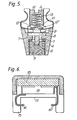
- the pressure sensor 3 is shown in more detail in Figures 5 and 6 and comprises a body 4 having a screw threaded bore 5 by which the body 4 is attached to the valve 2.
- a nose 6 projects into the bore 5 to actuate the spindle (not shown) of the valve and enable air under pressure to pass through the bore 5 and subsidiary bores 7 into a closed chamber 8.
- One wall of the chamber 8 is provided by a diaphragm 9 which carries a metal conductor 10.
- the metal conductor 10 and hence the diaphragm 9 is urged in a downward direction, as seen in the drawing, by a compression spring 11 to urge the metal conductor 10 into contact with electrical contacts 12, 12'.
- the spring 11 is received in a bore 13 of a screw 14 which is mounted in the body 4. Adjustment of the screw 14 enables the force exerted by the spring 11 to be adjusted and hence enables the pressure in the chamber 8 at which the metal conductor 10 will be urged into contact with the electrical contacts 12, 12' to be selected.
- the unit shown in Figure 5 is failsafe since air will not be released either by failure of the diaphragm 9 or on removal of the unit.
- the pressure sensor shown in Figures 1 and 3 also includes a transmitter unit shown in Figure 6.
- the transmitter unit comprises a body 15, a pair of spring loaded wires 16, 16' which project into an opening 17, a transmitter 18 for transmitting ultrasonic signals, and a cell 19.
- the wires 16, 16' are connected to the cell 19 and the transmitter 18 respectively, the cell 19 also being electrically connected to the transmitter 18.
- the transmitter unit shown in Figure 6 is snapped onto the body 4 shown in Figure 5 with the spring loaded wires 16, 16' contacting exposed extensions of the electrical contacts 12, 12' to form electrical connections therebetween and to retain the transmitter unit on the body 4.
- a transmitter unit 20 is mounted on the rim of the tyre 1 in a way similar to that of wheel balance weights. This enables a larger cell 19 or transmitter 18 to be used, to provide a longer life.
- a receiver 21 is mounted on the chassis of the vehicle in reasonably close proximity to the sensor 3. In general, if the receiver 21 is within three feet of the transmitter 18 then signals of reasonable strength will be received.
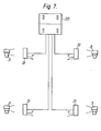
- the receiver 21 is connected to a remote display device 22 ( Figure 7) in the vehicle cab which, for example, may display a light on receipt of an ultrasonic signal by the receiver 21. An audible warning may be provided additionally or instead of the visual light.
- the pressure sensor is very compact and typically the transmitter 18 may have dimensions of between 12 and 15 mm by 4 mm, while the cell 19 need only supply about 1.5 volts.
- each sensor 3 is provided, one for each of four tyres (not shown), each sensor 3 having a corresponding receiver 21 linked to the display device 22.
- Each receiver 21 is powered by the vehicle electrical system and discrimination between the sensors 3 may be provided, as has previously been mentioned, either by limiting the power of each signal transmitted by the sensors 3, or by using ultrasonic signals of different frequencies.
Abstract
A pressure sensor for attachment to a tyre comprises sensing means (9) exposed to the pressure of the tyre in use and movable against resilience (11) in response to changes in the tyre pressure; and transmitting means (not shown) connected to an electrical circuit. The arrangement is such that on movement of the sensing means (9) in excess of a predetermined amount an electrical current is caused to flow in the electrical circuit, the electrical current causing the transmitting means to transmit a signal.
Description
- The invention relates to a pressure sensor for attachment to a tyre.
- It is important, particularly in the case of commercial vehicles, for tyre pressures to be frequently checked to ensure that there has not been a significant loss in pressure, which can be dangerous and may in some cases result in destruction of the tyre. Up until now, it has therefore been necessary for frequent checks on individual tyres to be carried out which is clearly time-consuming.
- In accordance with the present invention, a pressure sensor for attachment to a tyre comprises sensing means exposed to the pressure of the tyre in use and movable against resilience in response to changes in the tyre pressure;and transmitting means connected to an electrical circuit, the arrangement being such that on movement of the sensing means in excess of a predetermined amount an electrical current is caused to . in the electrical circuit, the electrical current flow causing the transmitting means to transmit a signal.
- With this sensor, the tyre:pressure is constantly monitored and as soon as the pressure drops below an acceptable value, the transmitting means will transmit a suitable warning signal. Of course, the sensor could also be utilised to detect an over-pressure in the tyre.
- Preferably, the sensor comprises a body which can be mounted on the valve of a tyre, the body having means for depressing the valve spindle to enable air under pressure in the tyre to communicate with a chamber within the body, a wall part of the chamber providing the sensing means. This enables the sensor conveniently to be mounted to the tyre where it simply substitutes for the conventional valve protection cap.
- The sensing means may comprise:a diaphragm carrying a metal connector. Preferably, where the sensor is to sense a decrease in pressure, the diaphragm is resiliently urged in a direction to cause the metal connector to contact electrical contacts of the electrical circuit. The resilient urging may be provided by a compression spring the force exerted by which is adjustable. This enables the pressure at which an electrical current is caused to flow in the electrical circuit to be selected.
- Alternatively, the sensor may include current generating means, such as a piezoelectric crystal, such that movement of the sensing means against resilience in excess of a predetermined amount activates the current generating means to cause a current to flow in the electrical circuit.
- The transmitting means is preferably mounted in a unit which clips onto a body housing the sensing means in such a way that the transmitting means forms part of the electrical circuit. Alternatively, the transmitting means may be mounted on the wheel hub or tyre separately from the sensing means, or on a valve housing.
- Preferably, the transmitting means transmits an ultrasonic signal.
- In one convenient arrangement, the pressure sensor is utilised in a pressure monitoring apparatus having receiving means for receiving the transmitted signal and providing an output signal. Conveniently, the receiving means is mounted to a part of the vehicle adjacent the tyre, means being provided to guide the output signal from the receiving means to a position in the vehicle where a visual or aural warning signal may be emitted.
- If such a pressure monitoring apparatus is provided for each tyre on the vehicle then each transmitting means may be arranged to transmit signals at different frequencies or with different powers to avoid a signal from one transmitting means being received by receiving means associated with another transmitting means.
- An example of a pressure monitoring apparatus including a pressure sensor in accordance with the present invention will now be described with reference to the accompanying diagrammatic drawings, in which:-
- Figure 1 is a cross-section through a tyre of a vehicle on which is mounted the pressure sensor;
- Figure 2 is a view similar to Figure 1 but showing a modified pressure sensor;
- Figure 3 illustrates in more detail the arrangement of Figure 1;
- Figure 4 illustrates in more detail the arrangement of Figure 2;
- Figure 5 is a section taken through a part of the pressure sensor shown in Figures 1 and 3;
- Figure 6 is a section taken through another part of the pressure sensor shown in Figures 1 and 3; and
- Figure 7 illustrates apparatus for receiving transmitted signals from four transmitting means.
- Figures 1 and 3 illustrate a vehicle tyre 1 having a
Schraeder valve 2 on which is mounted apressure sensor 3. Thepressure sensor 3 is shown in more detail in Figures 5 and 6 and comprises abody 4 having a screw threaded bore 5 by which thebody 4 is attached to thevalve 2. Anose 6 projects into the bore 5 to actuate the spindle (not shown) of the valve and enable air under pressure to pass through the bore 5 and subsidiary bores 7 into a closed chamber 8. - One wall of the chamber 8 is provided by a diaphragm 9 which carries a
metal conductor 10. Themetal conductor 10 and hence the diaphragm 9 is urged in a downward direction, as seen in the drawing, by a compression spring 11 to urge themetal conductor 10 into contact withelectrical contacts 12, 12'. The spring 11 is received in abore 13 of ascrew 14 which is mounted in thebody 4. Adjustment of thescrew 14 enables the force exerted by the spring 11 to be adjusted and hence enables the pressure in the chamber 8 at which themetal conductor 10 will be urged into contact with theelectrical contacts 12, 12' to be selected. - As may be seen, the unit shown in Figure 5 is failsafe since air will not be released either by failure of the diaphragm 9 or on removal of the unit.
- The pressure sensor shown in Figures 1 and 3 also includes a transmitter unit shown in Figure 6. The transmitter unit comprises a
body 15, a pair of spring loadedwires 16, 16' which project into an opening 17, atransmitter 18 for transmitting ultrasonic signals, and acell 19. Thewires 16, 16' are connected to thecell 19 and thetransmitter 18 respectively, thecell 19 also being electrically connected to thetransmitter 18. In use, the transmitter unit shown in Figure 6 is snapped onto thebody 4 shown in Figure 5 with the spring loadedwires 16, 16' contacting exposed extensions of theelectrical contacts 12, 12' to form electrical connections therebetween and to retain the transmitter unit on thebody 4. - This arrangement is particularly useful since the transmitter unit can be easily removed in order to replace the
cell 19 or to adjust thescrew 14 and in the case where thevalve 2 extends generally radially inwardly there is little danger of separation between thebodies body 15 onto thebody 4. - In a modified construction shown in Figures 2 and 4, a
transmitter unit 20 is mounted on the rim of the tyre 1 in a way similar to that of wheel balance weights. This enables alarger cell 19 ortransmitter 18 to be used, to provide a longer life. - As can be seen in Figures 1 and 2, a
receiver 21 is mounted on the chassis of the vehicle in reasonably close proximity to thesensor 3. In general, if thereceiver 21 is within three feet of thetransmitter 18 then signals of reasonable strength will be received. Thereceiver 21 is connected to a remote display device 22 (Figure 7) in the vehicle cab which, for example, may display a light on receipt of an ultrasonic signal by thereceiver 21. An audible warning may be provided additionally or instead of the visual light. - The pressure sensor is very compact and typically the
transmitter 18 may have dimensions of between 12 and 15 mm by 4 mm, while thecell 19 need only supply about 1.5 volts. - In the arrangement shown in Figure 7, four
sensors 3 are provided, one for each of four tyres (not shown), eachsensor 3 having acorresponding receiver 21 linked to thedisplay device 22. Eachreceiver 21 is powered by the vehicle electrical system and discrimination between thesensors 3 may be provided, as has previously been mentioned, either by limiting the power of each signal transmitted by thesensors 3, or by using ultrasonic signals of different frequencies. - In use, if the pressure in a tyre decreases then the pressure in the chamber 8 will decrease resulting in the spring 11 forcing the
metal conductor 10 into contact with theelectrical contacts 12, 12'. This will complete the electrical circuit including thecell 19 and thetransmitter 18 resulting in the transmission of an ultrasonic signal. This will be received by theappropriate receiver 21 resulting in the display of a light by thedevice 22.
Claims (10)
1. A pressure sensor for attachment to a tyre, the pressure sensor comprising sensing means (9) exposed to the pressure of the tyre in use and movable against.resilience (11) in response to changes in the tyre pressure; and transmitting means (18) connected to an electrical circuit, the arrangement being such that on movement of the sensing means (9) in excess of a predetermined amount an electrical current is caused to flow in the electrical circuit, the electrical current causing the transmitting means (18) to transmit a signal.
2. A pressure sensor according to claim 1, wherein the sensor comprises a body (4) which can be mounted on the valve (2) of a tyre, the body having means (6) for depressing the valve spindle to enable air under pressure in the tyre to communicate with a chamber (8) within the body, a wall part (9) of the chamber providing the sensing means.
3. A pressure sensor according to claim 1 or claim 2, wherein the sensing means comprises a diaphragm (9) carrying a metal connector (10).
4. A pressure sensor according to claim 3 for sensing a decrease in pressure, wherein the diaphragm (9) is resiliently urged in a direction to cause the metal connector (9) to contact electrical contacts (12, 12') of the electrical circuit.
5. A pressure sensor according to claim 1 or claim 2, further including current generating means, such that movement of the sensing means (9) against resilience in excess of a predetermined amount activates the current generating means to cause a current to flowin the electrical circuit.
6. A pressure sensor according to any of the preceding claims, wherein the resilience is provided by a compression spring (11) the force exerted by which is adjustable.
7. A pressure sensor according to any of the preceding claims, wherein the transmitting means (18) is mounted in a unit which clips onto a body housing the sensing means (9) in such a way that the transmitting means forms part of the electrical circuit.
8. A pressure sensor according to any of the preceding claims, wherein the transmitting means (18) transmits an ultrasonic signal.
9. Pressure monitoring apparatus including a pressure sensor in accordance with any of the preceding claims, the monitoring apparatus including receiving means (21) for receiving the transmitted signal and providing an output signal.
10. A vehicle having a plurality of tyres; pressure monitoring apparatus according to claim 10 including a pressure sensor associated with each tyre; and warning means (22) arranged to receive the output signals and to provide a visual or aural warning signal.
Applications Claiming Priority (2)
| Application Number | Priority Date | Filing Date | Title |
|---|---|---|---|
| GB8224738 | 1982-08-27 | ||
| GB8224738 | 1982-08-27 |
Publications (2)
| Publication Number | Publication Date |
|---|---|
| EP0104778A2 true EP0104778A2 (en) | 1984-04-04 |
| EP0104778A3 EP0104778A3 (en) | 1985-12-04 |
Family
ID=10532580
Family Applications (1)
| Application Number | Title | Priority Date | Filing Date |
|---|---|---|---|
| EP83304963A Withdrawn EP0104778A3 (en) | 1982-08-27 | 1983-08-26 | Pressure sensor |
Country Status (1)
| Country | Link |
|---|---|
| EP (1) | EP0104778A3 (en) |
Cited By (2)
| Publication number | Priority date | Publication date | Assignee | Title |
|---|---|---|---|---|
| DE3841995C1 (en) * | 1988-12-14 | 1990-06-13 | Moto Meter Ag, 7250 Leonberg, De | Pressure switch for monitoring the pressure in the tyre of a motor vehicle wheel |
| CN109606036A (en) * | 2018-12-26 | 2019-04-12 | 保汇通(厦门)网络科技有限公司 | A kind of external tire pressure detection method |
Citations (4)
| Publication number | Priority date | Publication date | Assignee | Title |
|---|---|---|---|---|
| US2063452A (en) * | 1934-01-10 | 1936-12-08 | James W Mcdonnell | Tire pressure indicating system |
| US3296590A (en) * | 1963-08-01 | 1967-01-03 | Rd Products | Tire pressure indicator |
| US3430196A (en) * | 1966-06-16 | 1969-02-25 | Rd Products | Tire pressure indicator |
| US3533063A (en) * | 1966-12-09 | 1970-10-06 | George E Garcia | Low pressure pneumatic tire transmitter |
-
1983
- 1983-08-26 EP EP83304963A patent/EP0104778A3/en not_active Withdrawn
Patent Citations (4)
| Publication number | Priority date | Publication date | Assignee | Title |
|---|---|---|---|---|
| US2063452A (en) * | 1934-01-10 | 1936-12-08 | James W Mcdonnell | Tire pressure indicating system |
| US3296590A (en) * | 1963-08-01 | 1967-01-03 | Rd Products | Tire pressure indicator |
| US3430196A (en) * | 1966-06-16 | 1969-02-25 | Rd Products | Tire pressure indicator |
| US3533063A (en) * | 1966-12-09 | 1970-10-06 | George E Garcia | Low pressure pneumatic tire transmitter |
Cited By (2)
| Publication number | Priority date | Publication date | Assignee | Title |
|---|---|---|---|---|
| DE3841995C1 (en) * | 1988-12-14 | 1990-06-13 | Moto Meter Ag, 7250 Leonberg, De | Pressure switch for monitoring the pressure in the tyre of a motor vehicle wheel |
| CN109606036A (en) * | 2018-12-26 | 2019-04-12 | 保汇通(厦门)网络科技有限公司 | A kind of external tire pressure detection method |
Also Published As
| Publication number | Publication date |
|---|---|
| EP0104778A3 (en) | 1985-12-04 |
Similar Documents
| Publication | Publication Date | Title |
|---|---|---|
| US5109213A (en) | Tire pressure monitor | |
| US5774047A (en) | Tire pressure sensing system including improved switch and location indicator | |
| US4137520A (en) | Tire pressure indicator system | |
| EP0431217B1 (en) | Delta P/delta t pressure sensor system | |
| EP1700719B1 (en) | Electronic wireless tire pressure monitoring apparatus | |
| US5119066A (en) | Pressure sensor system | |
| US5289160A (en) | Tire pressure monitoring system | |
| US5987980A (en) | In situ tire valve assembly employing short valve element as antenna | |
| US5717135A (en) | Tire pressure monitoring system utilizing a pressure activated transducer and sensor | |
| US4246567A (en) | Device for detecting and indicating low pressure and high heat in pneumatic tires | |
| US4890090A (en) | Pressure alarm system for motor vehicle tires | |
| US6100798A (en) | Tire pressure detecting/warning apparatus | |
| GB1100741A (en) | A pneumatically operated automatic device, for electrically signalling the values of pressure existing in pneumatic tires of motor vehicles | |
| US5055826A (en) | Pressure sensor system | |
| CN1326717C (en) | Tyre blow-out detector | |
| US5491465A (en) | Tire air pressure system | |
| EP1792757B1 (en) | Tire condition monitoring system | |
| US4196414A (en) | Integral tire inflation valve and tire height sensor | |
| EP0159133A2 (en) | Low tyre pressure warning devices | |
| EP0657314B1 (en) | Apparatus for alarming tyre deflation | |
| EP0104778A2 (en) | Pressure sensor | |
| EP0351997A2 (en) | Safety device for tyres | |
| WO1999039171A1 (en) | Apparatus for measuring multiple pressures | |
| GB2171548A (en) | Tyre inflation alarms | |
| US5754102A (en) | Apparatus for alarming of tire deflation |
Legal Events
| Date | Code | Title | Description |
|---|---|---|---|
| PUAI | Public reference made under article 153(3) epc to a published international application that has entered the european phase |
Free format text: ORIGINAL CODE: 0009012 |
|
| AK | Designated contracting states |
Designated state(s): DE FR GB IT NL SE |
|
| PUAL | Search report despatched |
Free format text: ORIGINAL CODE: 0009013 |
|
| AK | Designated contracting states |
Designated state(s): DE FR GB IT NL SE |
|
| STAA | Information on the status of an ep patent application or granted ep patent |
Free format text: STATUS: THE APPLICATION IS DEEMED TO BE WITHDRAWN |
|
| 18D | Application deemed to be withdrawn |
Effective date: 19860303 |