EP0104539B1 - Apparatus for reducing the resistant moment of combustion engines, especially diesel engines, in decelerating lorries - Google Patents
Apparatus for reducing the resistant moment of combustion engines, especially diesel engines, in decelerating lorries Download PDFInfo
- Publication number
- EP0104539B1 EP0104539B1 EP83109049A EP83109049A EP0104539B1 EP 0104539 B1 EP0104539 B1 EP 0104539B1 EP 83109049 A EP83109049 A EP 83109049A EP 83109049 A EP83109049 A EP 83109049A EP 0104539 B1 EP0104539 B1 EP 0104539B1
- Authority
- EP
- European Patent Office
- Prior art keywords
- combustion engine
- revolutions
- signal
- accelerator pedal
- power control
- Prior art date
- Legal status (The legal status is an assumption and is not a legal conclusion. Google has not performed a legal analysis and makes no representation as to the accuracy of the status listed.)
- Expired
Links
Images


Classifications
-
- F—MECHANICAL ENGINEERING; LIGHTING; HEATING; WEAPONS; BLASTING
- F02—COMBUSTION ENGINES; HOT-GAS OR COMBUSTION-PRODUCT ENGINE PLANTS
- F02D—CONTROLLING COMBUSTION ENGINES
- F02D41/00—Electrical control of supply of combustible mixture or its constituents
- F02D41/0002—Controlling intake air
- F02D41/0005—Controlling intake air during deceleration
-
- F—MECHANICAL ENGINEERING; LIGHTING; HEATING; WEAPONS; BLASTING
- F02—COMBUSTION ENGINES; HOT-GAS OR COMBUSTION-PRODUCT ENGINE PLANTS
- F02D—CONTROLLING COMBUSTION ENGINES
- F02D41/00—Electrical control of supply of combustible mixture or its constituents
- F02D41/30—Controlling fuel injection
- F02D41/38—Controlling fuel injection of the high pressure type
- F02D41/40—Controlling fuel injection of the high pressure type with means for controlling injection timing or duration
- F02D41/406—Electrically controlling a diesel injection pump
- F02D41/407—Electrically controlling a diesel injection pump of the in-line type
-
- F—MECHANICAL ENGINEERING; LIGHTING; HEATING; WEAPONS; BLASTING
- F02—COMBUSTION ENGINES; HOT-GAS OR COMBUSTION-PRODUCT ENGINE PLANTS
- F02B—INTERNAL-COMBUSTION PISTON ENGINES; COMBUSTION ENGINES IN GENERAL
- F02B3/00—Engines characterised by air compression and subsequent fuel addition
- F02B3/06—Engines characterised by air compression and subsequent fuel addition with compression ignition
-
- F—MECHANICAL ENGINEERING; LIGHTING; HEATING; WEAPONS; BLASTING
- F02—COMBUSTION ENGINES; HOT-GAS OR COMBUSTION-PRODUCT ENGINE PLANTS
- F02D—CONTROLLING COMBUSTION ENGINES
- F02D41/00—Electrical control of supply of combustible mixture or its constituents
- F02D41/0002—Controlling intake air
- F02D2041/0022—Controlling intake air for diesel engines by throttle control
-
- F—MECHANICAL ENGINEERING; LIGHTING; HEATING; WEAPONS; BLASTING
- F02—COMBUSTION ENGINES; HOT-GAS OR COMBUSTION-PRODUCT ENGINE PLANTS
- F02D—CONTROLLING COMBUSTION ENGINES
- F02D2250/00—Engine control related to specific problems or objectives
- F02D2250/18—Control of the engine output torque
-
- F—MECHANICAL ENGINEERING; LIGHTING; HEATING; WEAPONS; BLASTING
- F02—COMBUSTION ENGINES; HOT-GAS OR COMBUSTION-PRODUCT ENGINE PLANTS
- F02D—CONTROLLING COMBUSTION ENGINES
- F02D9/00—Controlling engines by throttling air or fuel-and-air induction conduits or exhaust conduits
- F02D9/08—Throttle valves specially adapted therefor; Arrangements of such valves in conduits
- F02D9/10—Throttle valves specially adapted therefor; Arrangements of such valves in conduits having pivotally-mounted flaps
- F02D9/1035—Details of the valve housing
- F02D9/1055—Details of the valve housing having a fluid by-pass
-
- Y—GENERAL TAGGING OF NEW TECHNOLOGICAL DEVELOPMENTS; GENERAL TAGGING OF CROSS-SECTIONAL TECHNOLOGIES SPANNING OVER SEVERAL SECTIONS OF THE IPC; TECHNICAL SUBJECTS COVERED BY FORMER USPC CROSS-REFERENCE ART COLLECTIONS [XRACs] AND DIGESTS
- Y02—TECHNOLOGIES OR APPLICATIONS FOR MITIGATION OR ADAPTATION AGAINST CLIMATE CHANGE
- Y02T—CLIMATE CHANGE MITIGATION TECHNOLOGIES RELATED TO TRANSPORTATION
- Y02T10/00—Road transport of goods or passengers
- Y02T10/10—Internal combustion engine [ICE] based vehicles
- Y02T10/40—Engine management systems
Definitions
- the invention relates to a method according to the preamble of independent claim 1.
- the method described in the preamble of independent claim 1 relates, for example according to FR-A-1 526125, to the pollutant components in the exhaust gas in the case of mixture-compressing and spark-ignited internal combustion engines in overrun or push operation by controlled opening of the throttle valve in conjunction with additional fuel supply reduce.
- This charge control which serves to improve the exhaust gas quality, is carried out in overrun mode up to a predetermined, minimum engine speed range of approx. 1400-1300 rpm. Above speeds in overrun are used in the execution of the method from the above.
- Known device as a signal for activating a control device acted upon by the intake manifold vacuum for separate actuation of the throttle valve and a valve for an additional fuel-air mixture.
- the known device Since the intake manifold vacuum is known to reach a size suitable for actuating mechanical devices only when the throttle valve is moved in the closed position, the known device is only suitable for a method for charge control in the range close to the aforementioned speed threshold. Furthermore, the additional charge caused in the exhaust gas of the internal combustion engine to reduce toxic components in the overrun mode is too low for a power output which significantly reduces the braking torque of the internal combustion engine and is also not provided.
- the speed signal used to control the control device for separate actuation of the power control element in overrun mode is derived from the pulses of an ignition device of the internal combustion engine.
- Electronic devices and a mechanical centrifugal governor are also suitable for this.
- the goal can be pursued, by increasing charge control in a vehicle with an internal combustion engine with a relatively high braking torque and a manual transmission when changing from drive to push mode To avoid wheel slip of the driven wheels.
- a relatively high braking torque of the machine can cause excessive wheel slip, especially when the accelerator is suddenly released, the road surface is smooth and the gearbox is briefly geared up.
- the wheel slip is determined and this is related to the respective vehicle speed. If a predetermined ratio of the two operating variables in overrun mode is exceeded, the operating medium supply to the internal combustion engine is increased by
- the essence of the invention is to derive a signal from the event that triggers a possible unstable driving state of the motor vehicle, namely an overrun that begins almost without delay, for direct activation of the
- Power control member of the internal combustion engine in order to reduce the braking power or the braking torque at the machine speed corresponding to the onset of overrun operation by delivering power or torque to a desired level by supplying charge.
- the advantage of the invention is therefore that, when the triggering event occurs, the reduction in braking power or braking torque is initiated and not only is valuable reaction time gained, but also the triggering of an unstable state is counteracted immediately and a risk is thus reduced.
- a slip-dependent control for reducing the braking torque is thus achieved.
- the invention can reduce the braking torque at the level of the gasoline engine by injecting a residual amount determined as a function of the engine speed in overrun mode. The remaining amount can be adapted further via the outside temperature, especially for winter operation.
- a further development of the invention deals with the problem of improving the control in such a way that it also reduces the braking torque in the long term or in the event of a fault in the control elements.
- the control of the Power output within a control loop in which the actual machine torque is compared with the target machine torque and, if there is no agreement, is brought into agreement with it.
- the torque actually output and the power actually output resulting from multiplying the torque by the speed can be determined in a simple manner. Do this performance or this moment agree with the corresponding setpoints, e.g. B. due to a fault or from tolerances of the control elements occurring in long-term operation, the control loop prevents the occurrence of excessive braking torque.
- FIG. 1 shows a diagram in which torque curves 1 and 2 for full and partial load are plotted against the engine speed "n" of an internal combustion engine in a first field.
- a braking torque curve 3 is specified via "n".
- a straight line 4 illustrates, for example, the change from a drive torque in 2 'to a non-reduced braking torque in 3' at the same machine speed "n” '.
- 5 denotes a curve for the reduced braking torque controlled by the machine speed “n”.
- the reduced braking torque for the load change illustrated by straight line 4 results in 5 '.
- the course of the reduced braking torque according to curve 5 can be achieved on an internal combustion engine by the continuous action of the device according to the invention on a main power control element or a bypass power control element.
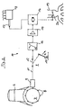
- FIG. 2 shows a device 10 in a schematic representation.
- An internal combustion engine 6 comprises a flywheel 7, with teeth 6, which are guided past an inductive sensor 9 of the device 10.
- the inductive transmitter 9 supplies a signal proportional to the machine speed "n".
- a switch 12, which is actuated via an accelerator pedal 13, is arranged in a line 11 for forwarding the signal. Switch 12 and accelerator pedal 13 are assigned to each other so that the switch 12 is closed at the latest when the accelerator pedal 13 is at rest. After the switch 12, the line 11 is continued to a threshold switch 14.
- the threshold switch 14 blocks those signals which correspond to an engine speed "n" corresponding to the idling speed "n, '.
- the speed 2" corresponding to the upper threshold value can be selected such that it is not reached by the internal combustion engine 6.
- a signal lying above the lower threshold value corresponding to the idling speed "'n /' is fed to an amplifier 15, which amplifies and forwards the signal to a servomotor 16.
- the servomotor 16 is mechanically operatively connected to a control rod 17 of an injection pump 16, which at serves as the main power control element of an internal combustion engine 6 operated according to the diesel process, whereas if the internal combustion engine 6 is equipped with a step carburetor 19 for the Otto process, the servomotor 16 can be mechanically operatively connected to the throttle valve 20 of the first stage as a bypass power control element.
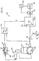
- the device 21 according to FIG. 3 comprises a first inductive sensor 22 which is driven by teeth 23 on a flywheel 24 of an internal combustion engine 25.
- a second inductive transmitter 26 is driven by the teeth of a ring gear 27 in an axle distributor gear 28 of a drive axle of the vehicle, not shown in detail.
- a manual transmission 29 is arranged between the axle distributor transmission 28 and the internal combustion engine 25.
- the speed signals of the two inductive sensors 22 and 26 are fed to a divider 30.
- the braking torque of the internal combustion engine 25 has an effect on the wheels of the drive axle in the reduced gears of the manual transmission 29.
- the divider 30 is therefore preferably designed such that it outputs an output signal "ü” to a control value generator 32 in the event of large differences between the speed of the ring gear 27 and the machine speed "n” caused by the reduced gears of the gearbox 29.
- the actuating value transmitter 32 stands with the inductive transmitter 22 on the internal combustion engine 25 via a Switch 33 in connection.
- the switch 33 is actuated via the accelerator pedal 31 and can be switched vehicle-specifically before or when the accelerator pedal 31 has reached the rest position.
- control signals "ö" are formed from the speed signals of the internal combustion engine 25 which are received when the switch 33 is closed and the output signals "ü" of the divider.
- the control signals "8" determined in a characteristic diagram over the machine speed “n” and the speed quotient "ü” of the divider 30 are increasingly passed on via a positioner 34 to a servomotor 35, which is a main power control element designated 36 or a Bypass power control element actuated.
- the organ 36 reports back to the positioner 34, which regulates the organ 36 via the servomotor 35 until the braking torque corresponding to the actuating signals "8" is reduced by additional fuel supply, for example in the case of a diesel internal combustion engine 25 or additional mixture supply in the case of an Otto engine 25 is reached.
- the reduction in the braking torque of the internal combustion engine 25 is limited to the reduced gears of the manual transmission 29.
- the divider 30 used for gear recognition can be designed in such a way that it does not emit an output signal "ü" in the gear ratios at the lower speeds and thus there is no reduction in the braking torque.
- the device 38 thus integrated in the main power control member 37 comprises a centrifugal governor 39 which is driven at a speed proportional to the engine speed "n".
- the regulator 39 acts via its sliding sleeve 40 and a linkage 41 on a pivot lever 42 which is rotatably mounted on an axis 43.
- a rotational speed adjusting lever 44 of the injection pump 37 is connected in a rotationally fixed manner to the rotational axis 43.
- This rotational speed adjusting lever 44 is actuated via an accelerator pedal 45.
- This speed controller can also be designed electrically.
- the speed adjustment lever 44 strikes against a stop 46 which is arranged on the pivot lever 42.
- the stop 46 When driving, the stop 46 is adjusted according to the machine speed "n" via the centrifugal force controller 39 in the direction of the arrow "A" to the speed adjusting lever 44 pivoted via the accelerator pedal 45.
- the speed adjustment lever 44 swiveling back according to arrow "B” strikes the following stop 46.
- the fuel injection pump 37 delivers an increased amount of fuel compared to its idle position via the speed adjustment lever 44 Internal combustion engine, so that the braking torque of the internal combustion engine is reduced in the push mode.
- the stop 46 With decreasing engine speed "n” in push mode, the stop 46 is finally pivoted back into the idling position and likewise the speed adjusting lever 44. Via the device 38 integrated in the injection pump 37 it is achieved that the power output of the internal combustion engine during overrun is dependent on the Machine speed "n” is controlled.
- a control circuit can additionally be superimposed on the control devices shown in FIGS. 2 to 4.
- a torque sensor (not shown), for example inductively operating, on the propeller shaft determines the machine torque actually output.
- a controller also not shown, detects deviations of this torque from the required torque given by curve 5 and, if necessary, corrects the torque given by a corresponding control intervention on the respective power control element.
Description
Die Erfindung betrifft ein Verfahren gemäß Oberbegriff des unabhängigen Anspruchs 1.The invention relates to a method according to the preamble of independent claim 1.
Das im Oberbegriff des unabhängigen Patentanspruches 1 beschriebene Verfahren bezieht sich beispielsweise gemäß der FR-A-1 526125 darauf, bei gemischverdichtenden und fremdgezündeten Brennkraftmaschinen im Schub- bzw. Schiebe-Betrieb die Schadstoffanteile im Abgas durch gesteuertes Öffnen der Drosselklappe in Verbindung mit zusätzlicher Kraftstoffzufuhr zu verringern. Diese der Verbesserung der Abgasqualität dienende Ladungssteuerung erfolgt im Schubbetrieb bis zu einem vorgegebenen, minimalen Motordrehzahlbereich von ca. 1400-1300 U/min. im Schubbetrieb darüber liegende Drehzahlen dienen bei der zur Durchführung des Verfahrens aus der o.g. Druckschrift bekannten Vorrichtung als Signal zur Aktivierung einer vom Saugrohrunterdruck beaufschlagten Steuereinrichtung zur gesonderten Betätigung der Drosselklappe sowie eines Ventils für zusätzliches Kraftstoff-Luftgemisch. Da der Saugrohrunterdruck bekanntlich erst mit in Richtung Schließstellung bewegter Drosselklappe eine zur Betätigung mechanischer Einrichtungen geeignete Größe erreicht, ist die bekannte Vorrichtung für ein Verfahren zur Ladungssteuerung lediglich in dem der vorgenannten Drehzahlschwelle nahen Bereich geeignet. Ferner ist die zur Senkung giftiger Anteile im Abgas der Brennkraftmaschine bewirkte zusätzliche Ladung im Schubbetrieb für eine hierbei das Bremsmoment der Brennkraftmaschine deutlich senkende Leistungsabgabe zu gering und auch nicht vorgesehen.The method described in the preamble of independent claim 1 relates, for example according to FR-A-1 526125, to the pollutant components in the exhaust gas in the case of mixture-compressing and spark-ignited internal combustion engines in overrun or push operation by controlled opening of the throttle valve in conjunction with additional fuel supply reduce. This charge control, which serves to improve the exhaust gas quality, is carried out in overrun mode up to a predetermined, minimum engine speed range of approx. 1400-1300 rpm. Above speeds in overrun are used in the execution of the method from the above. Known device as a signal for activating a control device acted upon by the intake manifold vacuum for separate actuation of the throttle valve and a valve for an additional fuel-air mixture. Since the intake manifold vacuum is known to reach a size suitable for actuating mechanical devices only when the throttle valve is moved in the closed position, the known device is only suitable for a method for charge control in the range close to the aforementioned speed threshold. Furthermore, the additional charge caused in the exhaust gas of the internal combustion engine to reduce toxic components in the overrun mode is too low for a power output which significantly reduces the braking torque of the internal combustion engine and is also not provided.
Bei der bekannten Vorrichtung wird das zur Ansteuerung der Steuereinrichtung zur gesonderten Betätigung des Leistungssteuerorgans im Schubbetrieb dienende Drehzahlsignal aus den Impulsen einer Zündeinrichtung der Brennkraftmaschine abgeleitet. Hierzu geeignet sind auch elektronische Einrichtungen sowie ein mechanischer Fliehkraftregler.In the known device, the speed signal used to control the control device for separate actuation of the power control element in overrun mode is derived from the pulses of an ignition device of the internal combustion engine. Electronic devices and a mechanical centrifugal governor are also suitable for this.
Weiter kann mit dem aus dem Oberbegriff des unabhängigen Patentanspruches beschriebenen Verfahren beispielsweise gemäß der DE-B-2 139 230 das ziel verfolgt werden, durch Ladungssteuerung bei einem Fahrzeug mit einer Brennkraftmaschine mit relativ hohem Bremsmoment und einem Schaltgetriebe beim wechsel von Antrieb auf Schiebebetrieb einen erhöhten Radschlupf der angetriebenen Räder zu vermeiden. Ein relativ hohes Bremsmoment der Maschine kann vor allem bei plötzlicher Gaswegnahme, glatter Fahrbahn und kurzer Übersetzung des Schaltgetriebes einen übermäßigen Radschlupf bewirken.Furthermore, with the method described in the preamble of the independent patent claim, for example according to DE-B-2 139 230, the goal can be pursued, by increasing charge control in a vehicle with an internal combustion engine with a relatively high braking torque and a manual transmission when changing from drive to push mode To avoid wheel slip of the driven wheels. A relatively high braking torque of the machine can cause excessive wheel slip, especially when the accelerator is suddenly released, the road surface is smooth and the gearbox is briefly geared up.
Bei der aus o.g. Druckschrift bekannten Vorrichtung zur Durchführung des Verfahrens der Ladungssteuerung wird der Radschlupf ermittelt und dieser mit der jeweiligen Fahrzeuggeschwindigkeit in Bezug gebracht. Bei Überschreitung eines vorbestimmten Verhältnisses beider Betriebsgrößen im Schubbetrieb wird die Betriebsmittelzufuhr zur Brennkraftmaschine erhöht, um durchIn the case of the above Known device for performing the method of charge control, the wheel slip is determined and this is related to the respective vehicle speed. If a predetermined ratio of the two operating variables in overrun mode is exceeded, the operating medium supply to the internal combustion engine is increased by
Leistungsabgabe das Bremsmoment zu reduzieren. Die bekannte Vorrichtung wird demnach schlupfabhängig gesteuert.Power output to reduce the braking torque. The known device is therefore controlled dependent on slip.
Der Nachteil dieser bekannten Vorrichtung ist, daß diese erst ab einem definierten Radschlupf wirksam das Bremsmoment reduziert. Dadurch geht wertvolle Reaktionszeit verloren. Weiter lassen sich mit einem definierten Radschlupf nicht alle zu einem instabilen Fahrzustand führenden Möglichkeiten beim Schubbetrieb erfassen.The disadvantage of this known device is that it effectively reduces the braking torque only from a defined wheel slip. As a result, valuable reaction time is lost. Furthermore, with a defined wheel slip, not all possibilities that lead to an unstable driving state can be detected during overrun.
Es ist daher Aufgabe der Erfindung, ein im Oberbegriff des unabhängigen Patentanspruches beschriebenes Verfahren so weiterzubilden und hierfür Vorrichtungen zur Durchführung des Verfahrens anzugeben, daß das Bremsmoment der Brennkraftmaschine vor dem Auftreten eines erhöhten Radschlupfes reduziert wird.It is therefore an object of the invention to develop a method described in the preamble of the independent claim and to provide devices for carrying out the method for this purpose that the braking torque of the internal combustion engine is reduced before the occurrence of increased wheel slip.
Diese Aufgabe wird gelöst durch die Merkmale des kennzeichnenden Teils des Anspruchs 1 bei einem Verfahren gemäß Oberbegriff dieses Anspruchs.This object is achieved by the features of the characterizing part of claim 1 in a method according to the preamble of this claim.
Kern der Erfindung ist, aus dem einen möglichen instabilen Fahrzustand des Kraftfahrzeuges auslösenden Ereignis, nämlich einem nahezu verzögerungsfrei einsetzenden Schubbetrieb, ein Signal abzuleiten zur unmittelbaren Ansteuerung desThe essence of the invention is to derive a signal from the event that triggers a possible unstable driving state of the motor vehicle, namely an overrun that begins almost without delay, for direct activation of the
Leistungssteuerorgans der Brennkraftmaschine, um durch Ladungszufuhr die Bremsleistung bzw. das Bremsmoment bei der mit einsetzendem Schubbetrieb entsprechenden Maschinendrehzahl durch Abgabe von Leistung bzw. Drehmoment auf ein gewünschtes Maß zu verringern.Power control member of the internal combustion engine in order to reduce the braking power or the braking torque at the machine speed corresponding to the onset of overrun operation by delivering power or torque to a desired level by supplying charge.
Der Vorteil der Erfindung liegt demnach darin, daß mit Eintritt des auslösenden Ereignisses bereits die Reduzierung der Bremsleistung bzw. des Bremsmomentes eingeleitet wird und damit nicht nur wertvolle Reaktionszeit gewonnen ist, sondern auch der Auslösung eines instabilen zustandes sofort entgegengewirkt und damit eine Gefährdung herabgesetzt wird. Damit ist eine schlupfunabhängige Steuerung zur Reduzierung des Bremsmomentes erreicht. Mit der Erfindung kann so beispielsweise bei Dieselmotoren durch Einspritzen einer in Abhängigkeit der Maschinen- Drehzahl bestimmten Restmenge im Schubbetrieb das Bremsmoment auf Ottomotoren-Niveau abgebaut werden. Dabei kann insbesondere für den Winterbetrieb die Restmenge über die Außentemperatur weiter angepaßt werden.The advantage of the invention is therefore that, when the triggering event occurs, the reduction in braking power or braking torque is initiated and not only is valuable reaction time gained, but also the triggering of an unstable state is counteracted immediately and a risk is thus reduced. A slip-dependent control for reducing the braking torque is thus achieved. In the case of diesel engines, for example, the invention can reduce the braking torque at the level of the gasoline engine by injecting a residual amount determined as a function of the engine speed in overrun mode. The remaining amount can be adapted further via the outside temperature, especially for winter operation.
Eine Weiterbildung der Erfindung beschäftigt sich mit dem Problem, die Steuerung dahingehend zu verbessern, daß sie auch langfristig bzw. bei einer Störung der Steuerungsorgane das Bremsmoment reduziert. Hierzu erfolgt die Steuerung der Leistungsabgabe innerhalb eines Regelkreises, bei dem das Ist-Maschinenmoment mit dem Soll-Maschinenmoment verglichen und bei fehlender Übereinstimmung mit diesem in Übereinstimmung gebracht wird.A further development of the invention deals with the problem of improving the control in such a way that it also reduces the braking torque in the long term or in the event of a fault in the control elements. The control of the Power output within a control loop, in which the actual machine torque is compared with the target machine torque and, if there is no agreement, is brought into agreement with it.
Durch die Bestimmung des Ist-Maschinenmomentes, beispielsweise mit Hilfe eines bekannten, an der Kardanwelle angeordneten induktiven Momentensensors kann auf einfache Weise das tatsächlich abgegebene Moment und die sich durch Multiplikation des Momentes mit der Drehzahl ergebende tatsächlich abgegebene Leistung bestimmt werden. Stimmen diese Leistung bzw. dieses Moment mit den entsprechenden Sollwerten, z. B. aufgrund einer Störung oder von im Langzeitbetrieb auftretenden Toleranzen der Steuerungsorgane, nicht überein, so verhindert der Regelkreis das Auftreten eines zu großen Bremsmomentes.By determining the actual machine torque, for example with the aid of a known inductive torque sensor arranged on the cardan shaft, the torque actually output and the power actually output resulting from multiplying the torque by the speed can be determined in a simple manner. Do this performance or this moment agree with the corresponding setpoints, e.g. B. due to a fault or from tolerances of the control elements occurring in long-term operation, the control loop prevents the occurrence of excessive braking torque.
Die Erfindung ist anhand von in der Zeichnung dargestellten Beispielen beschrieben. Es zeigen
- Fig. 1 ein Diagramm zur Veranschaulichung der Reduzierung des Bremsmomentes,
- Fig. 2 ein erstes Ausführungsbeispiel einer Vorrichtung, die über einen von der Fahrpedalstellung gesteuerten Schalter wirksam wird,
- Fig. 3 ein weiteres Ausführungsbeispiel einer Vorrichtung, die über einen von der Fahrpedalstellung gesteuerten Schalter und einem der Gangerkennung dienenden Dividierer wirksam wird,
- Fig. 4 ein weiteres Ausführungsbeispiel einer Vorrichtung, bei der über einen Drehzahlregler einer Einspritzpumpe ein Leerlauf-Anschlag eines Verstellhebels der Einspritzpumpe
- 1 is a diagram illustrating the reduction in braking torque,
- 2 shows a first exemplary embodiment of a device which takes effect via a switch controlled by the accelerator pedal position,
- 3 shows a further exemplary embodiment of a device which takes effect via a switch controlled by the accelerator pedal position and a divider which serves to identify the gear,
- Fig. 4 shows another embodiment of a device in which an idle stop of an adjusting lever of the injection pump via a speed controller of an injection pump
drehzahlabhängig verstellt wird. Fig. 1 zeigt ein Diagramm, in dem über der Maschinen-Drehzahl "n" einer Brennkraftmaschine in einem ersten Feld Drehmoment-Kurven 1 und 2 für Voll- und Teillast aufgetragen sind. In einem zweiten Feld ist über "n" eine Bremsmomentkurve 3 angegeben. Eine Gerade 4 veranschaulicht bei gleicher Maschinen-Drehzahl "n"' beispielsweise den Wechsel von einem Antriebsmoment in 2' zu einem nicht reduzierten Bremsmoment in 3'. Mit 5 ist eine Kurve für das über die Maschinen- Drehzahl "n" gesteuert reduzierte Bremsmoment bezeichnet. Das reduzierte Bremsmoment für den durch die Gerade 4 veranschaulichten Lastwechsel ergibt sich mit 5'. Der Verlauf des reduzierten Bremsmomentes gemäß der Kurve 5 kann an einer Brennkraftmaschine durch kontinuierliche Einwirkung der erfindungsgemäßen Vorrichtung auf ein Haupt-Leistungssteuerorgan oder ein Bypass-Leistungssteuerorgan erzielt werden.is adjusted depending on the speed. 1 shows a diagram in which torque curves 1 and 2 for full and partial load are plotted against the engine speed "n" of an internal combustion engine in a first field. In a second field, a
Fig. 2 zeigt eine Vorrichtung 10 in schematischer Darstellung. Eine Brennkraftmaschine 6 umfaßt eine Schwungscheibe 7, mit Zähnen 6, die an einem Induktivgeber 9 der Vorrichtung 10 vorbeigeführt sind. Der Induktivgeber 9 liefert ein der Maschinen-Drehzahl "n" proportionales Signal. In einer Leitung 11 zur Weiterleitung des Signals ist ein Schalter 12 angeordnet, der über ein Fahrpedal 13 betätigt wird. Schalter 12 und Fahrpedal 13 sind einander so zugeordnet, daß der Schalter 12 spätestens bei Ruhestellung des Fahrpedals 13 geschlossen ist. Nach dem Schalter 12 ist die Leitung 11 zu einem Schwellwertschalter 14 weitergeführt. Der Schwellwertschalter 14 sperrt solche Signale, die einer unter der Leerlaufdrehzahl "n,' entsprechenden Maschinen-Drehzahl "n" entsprechen. Die dem oberen Schwellwert entsprechende Drehzahl 2" kann so gewählt sein, daß sie von der Brennkraftmaschine 6 nicht erreicht wird. Ein über dem unteren Schwellwert entsprechend der Leerlauf-Drehzahl "'n/' liegendes Signal wird einem Verstärker 15 zugeführt, der das Signal verstärkt an einen Stellmotor 16 weiterleitet. Der Stellmotor 16 steht in mechanischer Wirkverbindung mit einer Regelstange 17 einer Einspritzpumpe 16, die bei einer nach dem Dieselverfahren betriebenen Brennkraftmaschine 6 als Haupt-Leistungssteuerorgan dient. Ist dagegen die Brennkraftmaschine 6 für das Otto-Verfahren mit einem Stufenvergaser 19 ausgerüstet, so kann der Stellmotor 16 mit der Drosselklappe 20 der ersten Stufe als Bypass-Leistungssteuerorgan mechanisch in Wirkverbindung stehen.2 shows a
In beiden Fällen wird bei einem während des Fahrbetriebes losgelassenem, in die Ruhestellung zurückgekehrten Fahrpedal 13 durch das der jeweiligen Maschinen-Drehzahl "n" entsprechende Signal des Induktivgebers 9 das Bremsmoment der Brennkraftmaschine 6 durch zusätzliche Einspritzung oder zusätzliche Gemischzufuhr reduziert.In both cases, when the accelerator pedal 13 is released during driving operation and has returned to the rest position, the braking torque of the internal combustion engine 6 is reduced by additional injection or additional mixture supply by the signal of the
Die Vorrichtung 21 nach Fig. 3 umfaßt einen ersten Induktivgeber 22, der von Zähnen 23 an einer Schwungscheibe 24 einer Brennkraftmaschine 25 angesteuert wird. Ein zweiter Induktivgeber 26 wird von den Zähnen eines Tellerrades 27 in einem Achsverteiler-Getriebe 28 einer nicht näher gezeigten Antriebsachse des Fahrzeuges angesteuert. Zwischen dem Achsverteiler-Getriebe 28 und der Brennkraftmaschine 25 ist ein Schaltgetriebe 29 angeordnet. Die Drehzahl-Signale der beiden Induktivgeber 22 und 26 werden einem Dividierer 30 zugeführt. Bei abruptem Übergang vom Fahrbetrieb in den Schiebebetrieb durch Loslassen eines Fahrpedals 31 wirkt sich bekanntlich das Bremsmoment der Brennkraftmaschine 25 in den untersetzten Gängen des Handschaltgetriebes 29 an den Rädern der Antriebsachse aus. Der Dividierer 30 ist daher vorzugsweise so ausgebildet, daß er bei großen, durch die untersetzten Gänge des Schaltgetriebes 29 bewirkten Unterschieden zwischen der Drehzahl des Tellerrades 27 und der Maschinen-Drehzahl "n" ein Ausgangssignal "ü" an einen Stellwertgeber 32 abgibt. Der Stellwertgeber 32 steht mit dem Induktivgeber 22 an der Brennkraftmaschine 25 über einen Schalter 33 in Verbindung. Der Schalter 33 wird über das Fahrpedal 31 betätigt und kann fahrzeugspezifisch vor oder mit Erreichen der Ruhestellung des Fahrpedals 31 geschaltet werden. Im Stellwertgeber 32 werden aus den bei geschlossenem Schalter 33 eingehenden Drehzahlsignalen der Brennkraftmaschine 25 und den Ausgangssignalen "ü" des Dividierers 30 Stellsignale "ö" gebildet. Die über der Maschinen-Drehzahl "n" und dem Drehzahl-Quotienten "ü" des Dividierers 30 in einem Kennfeld ermittelten Stellsignale "8" werden über einen Stellungsregler 34 verstärkt an einen Stellmotor 35 weitergegeben, der ein mit 36 bezeichnetes Haupt-Leistungssteuerorgan oder ein Bypass-Leistungssteuerorgan betätigt. Vom Organ 36 erfolgt eine Rückmeldung an den Stellungsregler 34, der über den Stellmotor 35 das Organ 36 so lange regelt, bis die den Stellsignalen "8" entsprechende Reduzierung des Bremsmomentes durch zusätzliche Kraftstoffzufuhr beispielsweise bei einer DieselBrennkraftmaschine 25 oder zusätzliche Gemischzufuhr bei einer Otto-Brennkraftmaschine 25 erreicht ist.The
Mit der Vorrichtung 21 ist die Reduzierung des Bremsmomentes der Brennkraftmaschine 25 auf die untersetzten Gänge des Schaltgetriebes 29 beschränkt. Schließlich kann der zur Gangerkennung dienende Dividierer 30 so ausgelegt sein, daß er in den untersetzten Gängen in den unteren Drehzahlen kein Ausgangssignal "ü" abgibt und somit keine Reduzierung des Bremsmomentes erfolgt.With the
Fig. 4 zeigt schließlich eine Diesel-Einspritzpumpe 37 mit einer integrierten Vorrichtung 36. Die somit im Haupt-Leistungssteuerorgan 37 integrierte Vorrichtung 38 umfaßt einen Fliehkraftregler 39, der mit einer zur Maschinen-Drehzahl "n" proportionalen Drehzahl angetrieben ist. Der Regler 39 wirkt über seine Schiebemuffe 40 und ein Gestänge 41 auf einen Schwenkhebel 42 ein, der auf einer Achse 43 drehbar gelagert ist. Mit der Drehachse 43 drehfest verbunden ist dagegen ein Drehzahl-Verstellhebel 44 der Einspritzpumpe 37. Dieser Drehzahl-Verstellhebel 44 wird über ein Fahrpedal 45 betätigt. Dieser Drehzahlregler kann auch elektrisch ausgeführt sein. Bei Leerlauf der nicht gezeigten Brennkraftmaschine schlägt der Drehzahl-Verstellhebel 44 gegen einen Anschlag 46, der am Schwenkhebel 42 angeordnet ist. Im Fahrbetrieb wird der Anschlag 46 entsprechend der Maschinen-Drehzahl "n" über den Fliehkraftregler 39 gemäß der Pfeilrichtung "A" dem über das Fahrpedal 45 verschwenkten Drehzahl-Verstellhebel 44 nachgeführt. Bei raschem Übergang vom Fahrbetrieb in den Schiebebetrieb schlägt der gemäß Pfeil "B" zurückschwenkende Drehzahl-Verstellhebel 44 gegen den nachgeführten Anschlag 46. Über den gegenüber seiner Leerlauf-Grundstellung abweichend positionierten Drehzahl-Verstellhebel 44 fördert die KraftstoffEinspritzpumpe 37 eine gegenüber der Leerlaufmenge erhöhte Kraftstoffmenge zur Brennkraftmaschine, so daß im Schiebbetrieb das Bremsmoment der Brennkraftmaschine reduziert wird. Mit sinkender Maschinen- Drehzahl "n" im Schiebebetrieb wird schließlich der Anschlag 46 in die Leerlaufposition zurückgeschwenkt und ebenso der Drehzahl-Verstellhebel 44. Über die in der Einspritzpumpe 37 integrierte Vorrichtung 38 ist erreicht, daß die Leistungsabgabe der Brennkraftmaschine beim Schubbetrieb in Abhängigkeit von der Maschinen-Drehzahl "n" gesteuert wird.4 finally shows a
Den in den Fig. 2 bis 4 dargestellten Steuerungs-Vorrichtungen kann zusätzlich ein Regelkreis überlagert sein. Dabei bestimmt ein nicht dargestellter, beispielsweise induktiv arbeitender Momentensensor an der Kardanwelle das tatsächlich abgegebene Maschinenmoment. Ein ebenfalls nicht dargestellter Regler stellt Abweichungen dieses Moments vom erforderlichen, durch die Kurve 5 gegebenen Moment fest und korrigiert ggf. das abgegebene Moment durch einen entsprechenden Regeleingriff am jeweiligen Leistungssteuerorgan.A control circuit can additionally be superimposed on the control devices shown in FIGS. 2 to 4. A torque sensor (not shown), for example inductively operating, on the propeller shaft determines the machine torque actually output. A controller, also not shown, detects deviations of this torque from the required torque given by
Claims (7)
Priority Applications (1)
| Application Number | Priority Date | Filing Date | Title |
|---|---|---|---|
| AT83109049T ATE34430T1 (en) | 1982-09-25 | 1983-09-14 | DEVICE FOR REDUCING THE BRAKING TORQUE OF INTERNAL COMBUSTION ENGINES, PARTICULARLY DIESEL ENGINES, IN MOTOR VEHICLES DURING OVERRUN. |
Applications Claiming Priority (4)
| Application Number | Priority Date | Filing Date | Title |
|---|---|---|---|
| DE3235619 | 1982-09-25 | ||
| DE19823235619 DE3235619A1 (en) | 1982-09-25 | 1982-09-25 | Device for reducing the brake torque of internal combustion engines, particularly diesel engines, in motor vehicles in overrun conditions |
| DE3328219 | 1983-08-04 | ||
| DE19833328219 DE3328219A1 (en) | 1983-08-04 | 1983-08-04 | Device for reducing the braking torque of internal combustion engines, especially diesel engines, in motor vehicles in overrun conditions |
Publications (3)
| Publication Number | Publication Date |
|---|---|
| EP0104539A2 EP0104539A2 (en) | 1984-04-04 |
| EP0104539A3 EP0104539A3 (en) | 1986-08-27 |
| EP0104539B1 true EP0104539B1 (en) | 1988-05-18 |
Family
ID=25804737
Family Applications (1)
| Application Number | Title | Priority Date | Filing Date |
|---|---|---|---|
| EP83109049A Expired EP0104539B1 (en) | 1982-09-25 | 1983-09-14 | Apparatus for reducing the resistant moment of combustion engines, especially diesel engines, in decelerating lorries |
Country Status (2)
| Country | Link |
|---|---|
| EP (1) | EP0104539B1 (en) |
| DE (1) | DE3376666D1 (en) |
Cited By (1)
| Publication number | Priority date | Publication date | Assignee | Title |
|---|---|---|---|---|
| DE102011076682A1 (en) | 2011-05-30 | 2012-12-06 | Bayerische Motoren Werke Aktiengesellschaft | Method and safety concept for detecting faults in a drive system of a motor vehicle |
Families Citing this family (5)
| Publication number | Priority date | Publication date | Assignee | Title |
|---|---|---|---|---|
| JPS60138248A (en) * | 1983-12-27 | 1985-07-22 | Diesel Kiki Co Ltd | Fuel injection device for internal-combustion engine |
| JPS61268536A (en) * | 1985-05-22 | 1986-11-28 | Toyota Motor Corp | Speed change control method for automatic transmission |
| DE3942862C2 (en) * | 1989-12-23 | 2001-04-12 | Bosch Gmbh Robert | Procedure for engine drag torque limitation |
| US5313922A (en) * | 1989-12-23 | 1994-05-24 | Robert Bosch Gmbh | Method for controlling a flow of fuel to an engine of a vehicle during overrun operation |
| AUPN072495A0 (en) * | 1995-01-24 | 1995-02-16 | Orbital Engine Company (Australia) Proprietary Limited | A method for controlling the operation of an internal combustion engine of a motor vehicle |
Family Cites Families (6)
| Publication number | Priority date | Publication date | Assignee | Title |
|---|---|---|---|---|
| DE1205843B (en) * | 1961-11-04 | 1965-11-25 | Daimler Benz Ag | Control device for adjusting the idling torque of internal combustion engines in motor vehicles |
| FR1526125A (en) * | 1967-04-06 | 1968-05-24 | Sibe | Improvements made to fuel systems for internal combustion engines of motor vehicles |
| DE2139230B2 (en) * | 1971-08-05 | 1975-06-26 | Teldix Gmbh, 6900 Heidelberg | Device for automatically influencing the set engine torque of a vehicle |
| DE2842389C2 (en) * | 1978-09-29 | 1984-04-12 | Robert Bosch Gmbh, 7000 Stuttgart | Device for setting the torque of an internal combustion engine |
| FR2459373A1 (en) * | 1979-06-19 | 1981-01-09 | Renault | METHOD OF REDUCING THE EMISSION OF HARMFUL GAS FROM A CARBURETTOR INTERNAL COMBUSTION ENGINE DURING DECELERATION PERIOD AND APPARATUS USING THE SAME |
| JPS57135238A (en) * | 1981-02-16 | 1982-08-20 | Nippon Denso Co Ltd | Electronic control type fuel injector |
-
1983
- 1983-09-14 DE DE8383109049T patent/DE3376666D1/en not_active Expired
- 1983-09-14 EP EP83109049A patent/EP0104539B1/en not_active Expired
Cited By (4)
| Publication number | Priority date | Publication date | Assignee | Title |
|---|---|---|---|---|
| DE102011076682A1 (en) | 2011-05-30 | 2012-12-06 | Bayerische Motoren Werke Aktiengesellschaft | Method and safety concept for detecting faults in a drive system of a motor vehicle |
| WO2012163633A1 (en) | 2011-05-30 | 2012-12-06 | Bayerische Motoren Werke Aktiengesellschaft | Method and safety concept for recognizing defects in a drive system of a motor vehicle |
| US9947148B2 (en) | 2011-05-30 | 2018-04-17 | Bayerische Motoren Werke Aktiengesellschaft | Method and safety concept for recognizing defects in a drive system of a motor vehicle |
| DE102011076682B4 (en) | 2011-05-30 | 2024-03-07 | Bayerische Motoren Werke Aktiengesellschaft | Method and safety concept for detecting errors in a drive system of a motor vehicle |
Also Published As
| Publication number | Publication date |
|---|---|
| DE3376666D1 (en) | 1988-06-23 |
| EP0104539A2 (en) | 1984-04-04 |
| EP0104539A3 (en) | 1986-08-27 |
Similar Documents
| Publication | Publication Date | Title |
|---|---|---|
| DE4141947C2 (en) | Control system for a propulsion unit in an aircraft | |
| DE4011850B4 (en) | A method of controlling an automated friction clutch operative between an engine and a transmission | |
| DE3843056C2 (en) | ||
| DE19712552C2 (en) | Device for controlling the ignition timing for internal combustion engines | |
| EP0525419B1 (en) | Device for controlling the output power of a vehicular power unit | |
| EP0760056B1 (en) | Process and device for controlling an internal combustion engine | |
| DE3504181A1 (en) | Device for controlling the intake air flow of internal combustion engines in motor vehicles | |
| DE3049398A1 (en) | ENGINE SPEED CONTROL SYSTEM | |
| WO1979000781A1 (en) | Device for regulating an engine-and-transmission unit in a motor vehicle | |
| DE4235827B4 (en) | Method and device for controlling the output power of a drive unit of a vehicle | |
| DE2163979A1 (en) | Fuel injection system | |
| DE2005097B2 (en) | Carburetor system for internal combustion engines for vehicle propulsion | |
| DE2712327A1 (en) | PROCEDURE FOR THE INDEPENDENT CONTROL OF MOTOR VEHICLES | |
| DE4334210C2 (en) | Control method for operating a drive unit of a vehicle | |
| DE3447764A1 (en) | FUEL CONTROL DEVICE FOR AN INTERNAL COMBUSTION ENGINE | |
| DE3400313C2 (en) | Device for regulating the recirculation of the exhaust gases of a diesel engine | |
| DE2824472B2 (en) | Method and arrangement for operating an internal combustion engine with spark ignition | |
| DE19712871A1 (en) | Coupling system | |
| EP0104539B1 (en) | Apparatus for reducing the resistant moment of combustion engines, especially diesel engines, in decelerating lorries | |
| DE3924953C2 (en) | ||
| DE3222363C2 (en) | ||
| EP0930424A2 (en) | Method and apparatus for improving startoff in a vehicle equipped with a manual gearbox | |
| DE3737698A1 (en) | CONTROL DEVICE FOR CONTROLLING THE DRIVE TORQUE OF AN INTERNAL COMBUSTION ENGINE OF A MOTOR VEHICLE | |
| DE3241024C2 (en) | ||
| DE4222457C2 (en) | Device for controlling the opening angle of a throttle valve in an internal combustion engine |
Legal Events
| Date | Code | Title | Description |
|---|---|---|---|
| PUAI | Public reference made under article 153(3) epc to a published international application that has entered the european phase |
Free format text: ORIGINAL CODE: 0009012 |
|
| AK | Designated contracting states |
Designated state(s): AT DE FR GB IT SE |
|
| EL | Fr: translation of claims filed | ||
| PUAL | Search report despatched |
Free format text: ORIGINAL CODE: 0009013 |
|
| AK | Designated contracting states |
Kind code of ref document: A3 Designated state(s): AT DE FR GB IT SE |
|
| 17P | Request for examination filed |
Effective date: 19860920 |
|
| 17Q | First examination report despatched |
Effective date: 19870130 |
|
| R17C | First examination report despatched (corrected) |
Effective date: 19870626 |
|
| GRAA | (expected) grant |
Free format text: ORIGINAL CODE: 0009210 |
|
| AK | Designated contracting states |
Kind code of ref document: B1 Designated state(s): AT DE FR GB IT SE |
|
| REF | Corresponds to: |
Ref document number: 34430 Country of ref document: AT Date of ref document: 19880615 Kind code of ref document: T |
|
| REF | Corresponds to: |
Ref document number: 3376666 Country of ref document: DE Date of ref document: 19880623 |
|
| ET | Fr: translation filed | ||
| ITF | It: translation for a ep patent filed |
Owner name: STUDIO JAUMANN |
|
| GBT | Gb: translation of ep patent filed (gb section 77(6)(a)/1977) | ||
| PLBI | Opposition filed |
Free format text: ORIGINAL CODE: 0009260 |
|
| 26 | Opposition filed |
Opponent name: ROBERT BOSCH GMBH Effective date: 19890216 |
|
| PGFP | Annual fee paid to national office [announced via postgrant information from national office to epo] |
Ref country code: SE Payment date: 19890818 Year of fee payment: 7 |
|
| PGFP | Annual fee paid to national office [announced via postgrant information from national office to epo] |
Ref country code: DE Payment date: 19890826 Year of fee payment: 7 |
|
| PGFP | Annual fee paid to national office [announced via postgrant information from national office to epo] |
Ref country code: FR Payment date: 19890928 Year of fee payment: 7 |
|
| PGFP | Annual fee paid to national office [announced via postgrant information from national office to epo] |
Ref country code: AT Payment date: 19890929 Year of fee payment: 7 |
|
| ITTA | It: last paid annual fee | ||
| PGFP | Annual fee paid to national office [announced via postgrant information from national office to epo] |
Ref country code: GB Payment date: 19890930 Year of fee payment: 7 |
|
| RDAG | Patent revoked |
Free format text: ORIGINAL CODE: 0009271 |
|
| STAA | Information on the status of an ep patent application or granted ep patent |
Free format text: STATUS: PATENT REVOKED |
|
| 27W | Patent revoked |
Effective date: 19900205 |
|
| GBPR | Gb: patent revoked under art. 102 of the ep convention designating the uk as contracting state | ||
| EUG | Se: european patent has lapsed |
Ref document number: 83109049.3 Effective date: 19900620 |