EP0104211B1 - Device for assorting orders of material stored in honeycomb shelvings - Google Patents
Device for assorting orders of material stored in honeycomb shelvings Download PDFInfo
- Publication number
- EP0104211B1 EP0104211B1 EP83901067A EP83901067A EP0104211B1 EP 0104211 B1 EP0104211 B1 EP 0104211B1 EP 83901067 A EP83901067 A EP 83901067A EP 83901067 A EP83901067 A EP 83901067A EP 0104211 B1 EP0104211 B1 EP 0104211B1
- Authority
- EP
- European Patent Office
- Prior art keywords
- paternoster
- lifting table
- shelf
- conveyor
- shelf conveyor
- Prior art date
- Legal status (The legal status is an assumption and is not a legal conclusion. Google has not performed a legal analysis and makes no representation as to the accuracy of the status listed.)
- Expired
Links
Images

Classifications
-
- B—PERFORMING OPERATIONS; TRANSPORTING
- B66—HOISTING; LIFTING; HAULING
- B66B—ELEVATORS; ESCALATORS OR MOVING WALKWAYS
- B66B9/00—Kinds or types of lifts in, or associated with, buildings or other structures
- B66B9/10—Kinds or types of lifts in, or associated with, buildings or other structures paternoster type
-
- B—PERFORMING OPERATIONS; TRANSPORTING
- B65—CONVEYING; PACKING; STORING; HANDLING THIN OR FILAMENTARY MATERIAL
- B65G—TRANSPORT OR STORAGE DEVICES, e.g. CONVEYORS FOR LOADING OR TIPPING, SHOP CONVEYOR SYSTEMS OR PNEUMATIC TUBE CONVEYORS
- B65G1/00—Storing articles, individually or in orderly arrangement, in warehouses or magazines
- B65G1/02—Storage devices
- B65G1/04—Storage devices mechanical
- B65G1/0442—Storage devices mechanical for elongated articles
Definitions
- the invention relates to a device for compiling material commissions from stored goods stored in a honeycomb rack system in the form of a rack conveyor that can be moved along the shelf along an end face of the shelf, on the lifting table of which the cassettes containing the stored goods are transferred for material removal.
- Honeycomb racks accommodate cassettes containing stacked goods one above the other and next to each other, which are stored in the racks like a drawer or removed from the racks.
- a shelf conveyor that can be moved along the shelf is used with a lifting table in the form of an operating station for moving to the shelf compartments.
- the cassettes containing the respective stored goods have so far been removed from the shelf with the help of an operator on the shelf conveyor and by means of a paternoster with a plurality of gondolas on the shelf that can be moved with the shelf conveyor on the front side of the shelf conveyor Corridor lowered, where the requested quantities of material are removed by a conveyor belt and put together for commission.
- This is labor and time consuming and unsuitable for long goods.
- the invention is based on the object of designing a device for compiling material commissions from stored goods, in particular also long goods, stored in a honeycomb racking system in a manner which permits more rational order picking.
- the object is achieved with a device of the type outlined at the outset, in which according to the invention the strand of the paternoster facing the shelf conveyor together with the lifting table of the shelf conveyor are assigned height-adjustable deflection slides which deflect the strand towards the lifting table.
- the picking is shifted to the lifting table that forms part of the racking conveyor and is designed as a working platform, and it takes place from the cassettes transferred from the rack to the lifting table into the gondolas forming part of the paternoster assigned to the racking truck, and in each case in the deflected towards the lifting table Gondola, which then also allows machine loading or removal from above.
- different commissions which can be taken from different cassettes, can be put together in one gondola and, on the other hand, a plurality of commissions in different gondolas. Obviously, this leads to a considerable reduction in labor and time required for picking.
- the paternoster can be used alternately, i.e. one of the paternosters can be loaded with the stored goods, while from the previously loaded one, for transfer to the loading the commissioned storage goods contained in the paternoster are removed. To do this, however, it is then necessary to provide guide columns for the deflection slides on the paternoster and to design the deflection slides so that they can be coupled to the lifting table.
- a paternoster which is detachably connected to the racking conveyor also opens up the possibility of using the racking conveyor for the re-storage of stored goods during the unloading of the paternoster loaded with picked goods.
- the paternoster can also be provided with a stationary deflection in this case on the side facing away from the shelf conveyor near the floor.
- a detachable assignment of the gondolas to the pateroster allows the gondolas to be fed as a whole, particularly at the loading station.
- the design of the lifting table forming part of the shelf conveyor as a working platform inevitably limits the lifting height of the lifting table in such a way that the uppermost compartments of the shelf can no longer be approached by the lifting table itself.
- an elevator covering the shelf compartments in the upper end position of the elevating table, which can no longer be approached by the lifting platform itself, is provided, into which the cassettes located in these shelf compartments are transferred and with which the cassettes are lowered onto the lifting table for material removal.
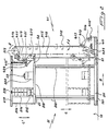
- FIG. 1 shows a honeycomb rack system partially shown with the order-picking device, in particular the paternoster assigned to the rack conveyor,
- FIG. 2 shows the order picking device in FIG. 1 in section along line 11-11 in FIG. 1.
- the honeycomb racking system consists of the shelves 11 and 11 'set up at a distance from one another to form an aisle 12, from which the containers 21, so-called cassettes, stored in the shelf compartments 111, 111', 111 "..., so-called cassettes, in the sense of Arrows A in Fig. 1 can be removed.
- the shelf conveyor 31 is formed from a trolley 311 with a lifting table 313 supported thereon via a lifting mechanism 312.
- the lifting table 313 can be adjusted in height by means of the lifting mechanism 312 in the sense of the double arrow C in FIG. 2.
- the paternoster 41 is erected on a chassis 411 and is formed by endless chains 415, 415 'which run around reversing wheels 413, 414 and on which the gondolas 412 are suspended in an oscillating manner (double arrow I E in Fig. 2).
- the paternoster 41 is provided with a deflection, formed by guide rollers 416, 417, towards the side remote from the shelf conveyor 31, which provides access to the gondola 412 'located in the deflecting area either for the removal of the gondola as a whole or for removal relieved of stored goods 22 located in the gondola.
- a deflection is also provided on the side of the paternoster 41 facing the shelf conveyor 31, in this case in the form of guideways 418 418 'which lead from carriages 411 of the paternoster 41 and which carry the conveyor chains 415, 415' in the direction guide rollers 420, 421, 422 deflecting onto the rack conveyor 31.
- the deflection slides 419 are detachably connected to the lifting table 313 of the shelf conveyor 31 (52) and are height-adjustable with this, guiding columns 418, 418 'forming part of the paternoster 41 in the sense of the double arrow C in FIG. 2, so that the to the shelf conveyor 31 coupled (51, 52) paternoster 41 on the side facing the shelf conveyor 31 is always deflected at the level of the lifting table 313 forming part of the shelf conveyor 31 and thus, at any height of the lifting table 313, the gondola 412 "forming part of the paternoster 41 and located in this deflection" Accessible from the lifting table 313 with loaded storage goods 22 that can be removed from cassettes 21 located on the lifting table 313.
- the drive for the paternoster 41 is designated 423.
- an elevator covering the shelves which can no longer be accessed by the lifting table 313 is provided on the lifting table 313, and the elevator car 315 in the elevator shaft 314 raised on the lifting table 2 to the level of the upper shelf compartments and can be lowered to the level of the lifting table 313 with a cassette 21 removed from the shelves.
- a cantilever frame 316/317 extending over the lifting table 313 serves on the one hand to mount a winch 318 for the car 315 and on the other hand as a running track for a gripper 319, with the stored goods 22 from a cassette 21 in the removal position on the lifting table 313, optionally after a Clipboard on a balance 320, which is still provided on the lifting table 313 and into which the nacelle 412 "located in the deflection formed by the deflection slide 419 is lifted.
- 424 denotes a control panel for the paternoster 41 which is accessible from the lifting table 313.
- a storage facility for the storage of long goods is shown, which does not exclude the use of the new order-picking device in connection with honeycomb racking systems receiving other stored goods.
Description
Die Erfindung betrifft eine Vorrichtung zur Zusammenstellung von Materialkommissionen aus in einer Wabenregalanlage eingelagertem Lagergut in Gestalt eines an einer Stirnseite des Regals an dem Regal entlang verfahrbaren Regalförderzeuges, auf dessen Hubtisch die das Lagergut enthaltenden Kassetten zur Materialentnahme überführt werden.The invention relates to a device for compiling material commissions from stored goods stored in a honeycomb rack system in the form of a rack conveyor that can be moved along the shelf along an end face of the shelf, on the lifting table of which the cassettes containing the stored goods are transferred for material removal.
Wabenregale nehmen über- und nebeneinander Lagergut enthaltende Kassetten auf, die schubkastenartig in die Regale eingelagert bzw. aus den Regalen entnommen werden. Zur Beschickung und Entnahme (DE- A Nr. 1925643) dient ein am Regal entlang verfahrbares Regalförderzeug mit einem Hubtisch in Form eines Bedienungsstandes zum Anfahren der Regalfächer. Zum Kommissionieren, das heisst zur Zusammenstellung von abgerufenem Lagergut, werden bislang die das jeweilige Lagergut enthaltenden Kassetten mit Hilfe einer Bedienungsperson auf dem Regalförderzeug aus dem Regal entnommen und mittels eines an der Stirnseite des Regalförderzeuges mit dem Regalförderzeug verfahrbaren Paternosters mit einer Mehrzahl von Gondeln auf den Flur abgesenkt, wo die abgerufenen Materialmengen durch ein Förderband abgeführt und zur Kommission zusammengestellt werden. Das ist arbeits- und zeitaufwendig und für Langgut ungeeignet.Honeycomb racks accommodate cassettes containing stacked goods one above the other and next to each other, which are stored in the racks like a drawer or removed from the racks. For loading and unloading (DE-A No. 1925643), a shelf conveyor that can be moved along the shelf is used with a lifting table in the form of an operating station for moving to the shelf compartments. For order picking, that is to say for the compilation of the stored goods, the cassettes containing the respective stored goods have so far been removed from the shelf with the help of an operator on the shelf conveyor and by means of a paternoster with a plurality of gondolas on the shelf that can be moved with the shelf conveyor on the front side of the shelf conveyor Corridor lowered, where the requested quantities of material are removed by a conveyor belt and put together for commission. This is labor and time consuming and unsuitable for long goods.
Ausgehend vom im vorausgehenden umrissenen Stand derTechnik liegt der Erfindung die Aufgabe zugrunde, eine Vorrichtung zur Zusammenstellung von Materialkommissionen aus in einer Wabenregalanlage eingelagertem Lagergut, insbesondere auch Langgut, in einer Weise auszugestalten, die einerationellere Kommissionierung zulässt.On the basis of the state of the art outlined above, the invention is based on the object of designing a device for compiling material commissions from stored goods, in particular also long goods, stored in a honeycomb racking system in a manner which permits more rational order picking.
Die Aufgabe wird mit einer Vorrichtung der eingangs umrissenen Art gelöst, bei der erfindungsgemäss dem dem Regalförderzeug zugekehrten Trum des Paternosters zusammen mit dem Hubtisch des Regalförderzeuges höhenverstellbare, das Trum zum Hubtisch hin auslenkende Auslenkschlitten zugeordnet sind.The object is achieved with a device of the type outlined at the outset, in which according to the invention the strand of the paternoster facing the shelf conveyor together with the lifting table of the shelf conveyor are assigned height-adjustable deflection slides which deflect the strand towards the lifting table.
Die Kommissionierung wird hierbei auf den Bestandteil des Regalförderzeuges bildenden, als Arbeitsbühne ausgelegten Hubtisch verlegt und sie erfolgt aus den aus dem Regal auf den Hubtisch überführten Kassetten in die Bestandteil des dem Regalförderzeug zugeordneten Paternosters bildenden Gondeln, und zwar jeweils in die gegen den Hubtisch hin ausgelenkte Gondel, die dann auch eine maschinelle Beschickung oder Entnahmevon oben zulässt. Ohne grössere Transportwege können somit einerseits unterschiedliche, aus verschiedenen Kassetten zu entnehmende Lagergüter aufweisende Kommissionen in jeweils einer Gondel und andererseits eine Mehrzahl von Kommissionen in verschiedenen Gondeln gleichzeitig zusammengestellt werden. Das führt ersichtlich zu einer ganz erheblichen Reduzierung an Arbeits-und Zeitaufwand bei der Kommissionierung.The picking is shifted to the lifting table that forms part of the racking conveyor and is designed as a working platform, and it takes place from the cassettes transferred from the rack to the lifting table into the gondolas forming part of the paternoster assigned to the racking truck, and in each case in the deflected towards the lifting table Gondola, which then also allows machine loading or removal from above. Without longer transport routes, on the one hand, different commissions, which can be taken from different cassettes, can be put together in one gondola and, on the other hand, a plurality of commissions in different gondolas. Obviously, this leads to a considerable reduction in labor and time required for picking.
Ist an jeder Stirnseite des Regalförderzeuges ein Paternoster vorgesehen und sind die Paternoster lösbar mit dem Regalförderzeug verbunden, können die Paternoster im Wechsel eingesetzt werden, das heisst einer der Paternoster kann mit abgerufenem Lagergut beschickt werden, während aus dem zuvor beschickten, zur Übergabe an die Verladung überführten Paternoster das in ihm enthaltene kommissionierte Lagergut entnommen wird. Dazu ist es dann allerdings erforderlich, für die Auslenkschlitten am Paternoster Führungssäulen vorzusehen und die Auslenkschlitten mit dem Hubtisch koppelbar auszubilden. Ein lösbar mit dem Regalförderzeug verbundener Paternoster eröffnet auch die Möglichkeit, während der Entladung des mit kommissioniertem Lagergut beschickten Paternosters das Regalförderzeug zur erneuten Einlagerung von Lagergut einzusetzen.If a paternoster is provided on each end of the shelf conveyor and the paternosters are detachably connected to the shelf conveyor, the paternoster can be used alternately, i.e. one of the paternosters can be loaded with the stored goods, while from the previously loaded one, for transfer to the loading the commissioned storage goods contained in the paternoster are removed. To do this, however, it is then necessary to provide guide columns for the deflection slides on the paternoster and to design the deflection slides so that they can be coupled to the lifting table. A paternoster which is detachably connected to the racking conveyor also opens up the possibility of using the racking conveyor for the re-storage of stored goods during the unloading of the paternoster loaded with picked goods.
Zur Erleichterung der Entnahme von in den Paternostergondeln befindlichem kommissioniertem Lagergut kann der Paternoster auch auf der vom Regalförderzeug abgekehrten Seite in Bodennähe mit einer in diesem Fall stationären Auslenkung versehen sein.In order to facilitate the removal of commissioned stored goods located in the paternoster gondolas, the paternoster can also be provided with a stationary deflection in this case on the side facing away from the shelf conveyor near the floor.
Eine lösbare Zuordnung der Gondeln zum Pater- noster gestattet es, die Gondeln zumal an der Verladestation als Ganzes der Verladung zuzuführen.A detachable assignment of the gondolas to the pateroster allows the gondolas to be fed as a whole, particularly at the loading station.
Die Ausgestaltung des Bestandteil des Regalförderzeuges bildenden Hubtisches als Arbeitsbühne begrenzt die Hubhöhe des Hubtisches zwangsläufig in einer Weise, dass die obersten Fächer des Regals vom Hubtisch selbst nicht mehr angefahren werden können. Um gleichwohl den Zugang zu den obersten Regalfächern zu ermöglichen, ist in weiterer Ausgestaltung der Erfindung auf dem Hubtisch ein die vom Hubtisch selbst nicht mehr anfahrbaren Regalfächer in der oberen Endlage des Hubtisches überdeckender Fahrstuhl vorgesehen, in den die in diesen Regalfächern befindlichen Kassetten überführt und mit dem die Kassetten auf den Hubtisch zur Materialentnahme abgesenkt werden.The design of the lifting table forming part of the shelf conveyor as a working platform inevitably limits the lifting height of the lifting table in such a way that the uppermost compartments of the shelf can no longer be approached by the lifting table itself. In order to nevertheless allow access to the uppermost shelf compartments, in a further embodiment of the invention, an elevator covering the shelf compartments in the upper end position of the elevating table, which can no longer be approached by the lifting platform itself, is provided, into which the cassettes located in these shelf compartments are transferred and with which the cassettes are lowered onto the lifting table for material removal.
Für die Überführung der das Lagergut enthaltenden Kassetten in die Regale und für ihre Entnahme aus den Regalen bedient man sich bekannter, auf dem Hubtisch des Regalförderzeuges anzuordnender Beschickungs- und Entnahmevorrichtungen. Mit Laufrollen versehene Kassetten können natürlich auch von Hand bewegt werden.For the transfer of the cassettes containing the stored goods to the shelves and for their removal from the shelves, known loading and removal devices to be arranged on the lifting table of the shelf conveyor are used. Cassettes with casters can of course also be moved by hand.
In der Zeichnung ist die Erfindung an einem in schematischer Weise dargestellten Ausführungsbeispiel weitergehend erläutert. Es zeigen:In the drawing, the invention is further explained using an exemplary embodiment shown in a schematic manner. Show it:
Fig. eine teilweise dargestellte Wabenregalanlage mit der Kommissioniervorrichtung, insbesondere den dem Regalförderzeug zugeordneten Paternoster,FIG. 1 shows a honeycomb rack system partially shown with the order-picking device, in particular the paternoster assigned to the rack conveyor,
Fig. 2 die Kommissioniervorrichtung in Fig. 1 im Schnitt nach Linie 11-11 in Fig. 1.2 shows the order picking device in FIG. 1 in section along line 11-11 in FIG. 1.
Die Wabenregalanlage besteht aus den im Abstand voneinander unter Bildung einer Gasse 12 aufgestellten Regalen 11 und 11', aus denen die in den Regalfächern 111, 111', 111"... eingelagerten, Lagergut 22 cnthaltenden Behälter 21, sogenannte Kassetten, im Sinne der Pfeile A in Fig. 1 entnehmbar sind.The honeycomb racking system consists of the
In der Gasse 12 ist ein schienengebundenes (121) Regalförderzeug 31 im Sinne des Doppelpfeiles B in Fig. 2 verfahrbar (fig. 2). Das Regalförderzeug 31 wird gebildet aus einem Fahrwerk 311 mit sich darauf über ein Hubwerk 312 abstützendem Hubtisch 313. Der Hubtisch 313 ist mittels des Hubwerks 312 im Sinne des Doppelpfeiles C in Fig. 2 höhenverstellbar. Mit dem die jeweiligen Regalfächer anfahrenden Regalförderzeug 31 werden die Lagergut 22 enthaltenden Kassetten 21 in die Regale 11,11', das heisst in die jeweiligen Regalfächer 111, 111', 111" ... eingelagert, gleichermassen werden Kassetten 21, aus denen Lagergut 22 entnommen werden soll, aus den Regalen 11, 11' auf das Regalförderzeug 31 zurück verlagert (Pfeile A in Fig. 1).In the
Nach der Erfindung ist an einer Stirnseite des Regalförderzeuges 31 ein ebenfalls schienengebundener (121) und dann auch im Sinne des Doppelpfeiles B in Fig. 2 verfahrbarer, mit einer Mehrzahl von Gondeln 412 bestückter Vertikal-Umlaufförderer 41, ein sogenannter Paternoster, vorgesehen, der mit dem Regalförderzeug 31 lösbar verbunden ist (51 ). Der Paternoster 41 ist aufgeständert auf einem Fahrwerk 411 und wird gebildet von um Umkehrräder 413, 414 geführten endlosen, im Sinne des Pfeiles D in Fig. 2 umlaufenden Ketten 415, 415', an denen die Gondeln 412 pendelnd aufgehängt sind (Doppelpfei-I E in Fig. 2). Im Bereich der unteren Umkehrräder 413 ist der Paternoster 41 mit einer von Führungsrollen 416,417 gebildeten Auslenkung nach der vom Regalförderzeug 31 abgekehrten Seite hin versehen, die die Zugänglichkeit zur im Auslenkbereich befindlichen Gondel 412' entweder für die Entnahme der Gondel als Ganzes oder aber für die Entnahme von in der Gondel befindlichem, abgerufenem Lagergut 22 erleichtert. Auf der dem Regalförderzeug 31 zugekehrten Seite des Paternosters 41 ist ebenfalls eine Auslenkung vorgesehen, in diesem Fall in Gestalt von sich an vom Fahrwerk 411 des Paternosters 41 ausgehenden Führungssäulen 418 418' führenden Schlitten 419, 419', in denen die Förderketten 415,415' in Richtung auf das Regalförderzeug 31 hin auslenkende Führungsrollen 420, 421, 422 gelagert sind. Die Auslenkschlitten 419 sind lösbar mit dem Hubtisch 313 des Regalförderzeuges 31 verbunden (52) und mit diesem, sich an den Bestandteil des Paternosters 41 bildenden Führungssäulen 418,418' führend im Sinne des Doppelpfeiles C in Fig. 2 höhenverstellbar, so dass der an das Regalförderzeug 31 angekoppelte (51, 52) Paternoster 41 auf der dem Regalförderzeug 31 zugekehrten Seite stets im Niveau des Bestandteil des Regalförderzeuges 31 bildenden Hubtisches 313 ausgelenkt ist und somit in jeder Höhenlage des Hubtisches 313 die Bestandteil des Paternosters 41 bildende, in dieser Auslenkung befindliche Gondel 412" vom Hubtisch 313 her zugänglich mit abgerufenem, aus auf dem Hubtisch 313 befindlichen Kassetten 21 entnehmbarem Lagergut 22 beladen werden kann. Mit 423 ist der Antrieb für den Paternoster 41 bezeichnet.According to the invention, an also rail-bound (121) and then also in the sense of the double arrow B in Fig. 2, equipped with a plurality of
Da der als Arbeitsbühne dienende Hubtisch 313 nicht bis auf das Niveau der obersten Regalfächer überhoben werden kann, ist auf dem Hubtisch 313 ein die von dem Hubtisch 313 nicht mehr anfahrbaren Regalfächer abdeckender Fahrstuhl vorgesehen, in dessen auf dem Hubtisch aufgeständerten Fahrschacht 314 der Fahrkorb 315 im Sinne des Doppelpfeiles C' in Fig. 2 auf das Niveau der oberen Regalfächer überhoben und mit einer aus den Regalen entnommenen Kassette 21 wieder auf das Niveau des Hubtisches 313 abgesenkt werden kann.Since the lifting table 313 serving as a working platform cannot be raised to the level of the uppermost shelf compartments, an elevator covering the shelves which can no longer be accessed by the lifting table 313 is provided on the lifting table 313, and the
Ein sich über den Hubtisch 313 erstreckendes Kragarmgerüst 316/317 dient einerseits der Lagerung einer Winde 318 für den Fahrkorb 315 und andererseits als Laufbahn für einen Greifer 319, mit dem Lagergut 22 aus einer auf dem Hubtisch 313 in Entnahmeposition befindlichen Kassette 21, gegebenenfalls nach einer Zwischenablage auf einer auf dem Hubtisch 313 noch vorgesehenen Waage 320, in die gerade in der vom Auslenkschlitten 419 gebildeten Auslenkung befindliche Gondel 412" überhoben wird. Mit 424 ist ein vom Hubtisch 313 herzugängliches Schaltpultfür den Paternoster 41 bezeichnet.A
Dargestellt ist eine Lagereinrichtung zur Einlagerung von Langgut, das schliesst die Anwendung der neuen Kommissioniervorrichtung in Verbindung mit anderes Lagergut aufnehmenden Wabenregalanlagen nicht aus.A storage facility for the storage of long goods is shown, which does not exclude the use of the new order-picking device in connection with honeycomb racking systems receiving other stored goods.
Claims (5)
Applications Claiming Priority (2)
| Application Number | Priority Date | Filing Date | Title |
|---|---|---|---|
| DE3211596A DE3211596A1 (en) | 1982-03-30 | 1982-03-30 | PICKING STAGE FOR ROD MATERIAL WITH CONVEYOR AND INITIAL LIFT COATING |
| DE3211596 | 1982-03-30 |
Publications (2)
| Publication Number | Publication Date |
|---|---|
| EP0104211A1 EP0104211A1 (en) | 1984-04-04 |
| EP0104211B1 true EP0104211B1 (en) | 1986-01-08 |
Family
ID=6159637
Family Applications (1)
| Application Number | Title | Priority Date | Filing Date |
|---|---|---|---|
| EP83901067A Expired EP0104211B1 (en) | 1982-03-30 | 1983-03-29 | Device for assorting orders of material stored in honeycomb shelvings |
Country Status (6)
| Country | Link |
|---|---|
| EP (1) | EP0104211B1 (en) |
| CH (1) | CH661705A5 (en) |
| DE (2) | DE3211596A1 (en) |
| NL (1) | NL8320097A (en) |
| SE (1) | SE456987B (en) |
| WO (1) | WO1983003405A1 (en) |
Families Citing this family (1)
| Publication number | Priority date | Publication date | Assignee | Title |
|---|---|---|---|---|
| DE4213565A1 (en) * | 1992-04-24 | 1993-10-28 | Keuro Maschinenbau Gmbh | Device for compiling material commissions from stored goods stored in a honeycomb racking system |
Family Cites Families (3)
| Publication number | Priority date | Publication date | Assignee | Title |
|---|---|---|---|---|
| DE296658C (en) * | ||||
| DE420096C (en) * | 1923-06-08 | 1925-10-15 | Hans Neubauer | Conveyor equipment for sea pigs and lifts |
| GB1211278A (en) * | 1968-05-21 | 1970-11-04 | King Ltd Geo W | Improvements in or relating to mechanical handling equipment |
-
1982
- 1982-03-30 DE DE3211596A patent/DE3211596A1/en not_active Withdrawn
-
1983
- 1983-03-29 EP EP83901067A patent/EP0104211B1/en not_active Expired
- 1983-03-29 CH CH6360/83A patent/CH661705A5/en not_active IP Right Cessation
- 1983-03-29 WO PCT/DE1983/000059 patent/WO1983003405A1/en active IP Right Grant
- 1983-03-29 NL NL8320097A patent/NL8320097A/en unknown
- 1983-03-29 DE DE8383901067T patent/DE3361759D1/en not_active Expired
- 1983-11-25 SE SE8306534A patent/SE456987B/en not_active IP Right Cessation
Also Published As
| Publication number | Publication date |
|---|---|
| SE8306534D0 (en) | 1983-11-25 |
| NL8320097A (en) | 1984-02-01 |
| CH661705A5 (en) | 1987-08-14 |
| EP0104211A1 (en) | 1984-04-04 |
| DE3361759D1 (en) | 1986-02-20 |
| DE3211596A1 (en) | 1983-10-06 |
| SE8306534L (en) | 1983-11-25 |
| SE456987B (en) | 1988-11-21 |
| WO1983003405A1 (en) | 1983-10-13 |
Similar Documents
| Publication | Publication Date | Title |
|---|---|---|
| EP3107860B1 (en) | Method and apparatus for storing and retrieving or shifting containers in high-bay warehouses | |
| EP3429947B1 (en) | System of a retrieval machine and a transport and handover system for storing and removing or relocating standard container in high-bay warehouses, and storage | |
| DE102014112994A1 (en) | order picking | |
| DE2509223C3 (en) | Load transfer device of a storage and retrieval vehicle | |
| EP0654425A1 (en) | Method of and device for storing and delivering or transferring load carriers into or out of a rack | |
| EP0518081A1 (en) | High shelving for stocking and de-stocking material in web form, particularly paper rolls, with rails in paired arrangement for stocking the paper rolls | |
| EP1716060A1 (en) | Method and system for operating a shelf in a commissioning system | |
| DE2154709C3 (en) | Storage and retrieval vehicle | |
| WO2019154815A1 (en) | Order-picking system | |
| EP1478584A1 (en) | Storage retrieval system comprising a load receiving element | |
| DE4031883A1 (en) | Storage and transfer system for pallets and containers - has transverse conveyors mounted on ends of shelves and on fork-lift truck | |
| DE4338717A1 (en) | Automatic parking and storage facility for motor vehicles | |
| DE3234817C2 (en) | High-bay warehouse | |
| EP0101459B2 (en) | Installation for storing and displacing pallets | |
| EP0116152A2 (en) | Device for storing and collecting elongated articles | |
| DE2758226C2 (en) | Goods magazine for containers, pallets or the like. | |
| DE1938473A1 (en) | Automatic high-performance storage system | |
| EP0104211B1 (en) | Device for assorting orders of material stored in honeycomb shelvings | |
| DE4210592A1 (en) | High bay warehouse | |
| DE3402996A1 (en) | PLANT FOR STORING AND REMOVING CONTAINERS USING A HIGH-BAY WAREHOUSE | |
| DE2163116A1 (en) | Shelf storage | |
| DE102015115323A1 (en) | Storage and retrieval unit | |
| DE2351835A1 (en) | IMPROVED METHOD OF STORAGE OF GOODS IN COMPOSITE CELL WAREHOUSES USING PUSH AND / OR LIFTING CONVEYORS | |
| DE4425780C2 (en) | Method and device for disposing of empty pallets from a rack warehouse | |
| DE19541123A1 (en) | Device for extending or retracting general cargo in a high-rise warehouse |
Legal Events
| Date | Code | Title | Description |
|---|---|---|---|
| PUAI | Public reference made under article 153(3) epc to a published international application that has entered the european phase |
Free format text: ORIGINAL CODE: 0009012 |
|
| AK | Designated contracting states |
Designated state(s): BE DE FR |
|
| 17P | Request for examination filed |
Effective date: 19840413 |
|
| GRAA | (expected) grant |
Free format text: ORIGINAL CODE: 0009210 |
|
| AK | Designated contracting states |
Designated state(s): BE DE FR |
|
| REF | Corresponds to: |
Ref document number: 3361759 Country of ref document: DE Date of ref document: 19860220 |
|
| ET | Fr: translation filed | ||
| RAP2 | Party data changed (patent owner data changed or rights of a patent transferred) |
Owner name: NEUHAEUSER, HELMUT, DIPL.-ING. |
|
| RIN2 | Information on inventor provided after grant (corrected) |
Free format text: THEOBALD, ADOLF |
|
| PLBE | No opposition filed within time limit |
Free format text: ORIGINAL CODE: 0009261 |
|
| STAA | Information on the status of an ep patent application or granted ep patent |
Free format text: STATUS: NO OPPOSITION FILED WITHIN TIME LIMIT |
|
| 26N | No opposition filed | ||
| BECN | Be: change of holder's name |
Effective date: 19860108 |
|
| REG | Reference to a national code |
Ref country code: FR Ref legal event code: TP |
|
| REG | Reference to a national code |
Ref country code: FR Ref legal event code: TP |
|
| PGFP | Annual fee paid to national office [announced via postgrant information from national office to epo] |
Ref country code: BE Payment date: 19890118 Year of fee payment: 7 |
|
| PGFP | Annual fee paid to national office [announced via postgrant information from national office to epo] |
Ref country code: FR Payment date: 19890131 Year of fee payment: 7 |
|
| PG25 | Lapsed in a contracting state [announced via postgrant information from national office to epo] |
Ref country code: BE Effective date: 19900331 |
|
| BERE | Be: lapsed |
Owner name: NEUHAUSER HELMUT Effective date: 19900331 |
|
| PG25 | Lapsed in a contracting state [announced via postgrant information from national office to epo] |
Ref country code: FR Effective date: 19901130 |
|
| REG | Reference to a national code |
Ref country code: FR Ref legal event code: ST |
|
| PGFP | Annual fee paid to national office [announced via postgrant information from national office to epo] |
Ref country code: DE Payment date: 19920304 Year of fee payment: 10 |
|
| PG25 | Lapsed in a contracting state [announced via postgrant information from national office to epo] |
Ref country code: DE Effective date: 19931201 |