EP0104171B1 - Lift mast assembly - Google Patents
Lift mast assembly Download PDFInfo
- Publication number
- EP0104171B1 EP0104171B1 EP82901388A EP82901388A EP0104171B1 EP 0104171 B1 EP0104171 B1 EP 0104171B1 EP 82901388 A EP82901388 A EP 82901388A EP 82901388 A EP82901388 A EP 82901388A EP 0104171 B1 EP0104171 B1 EP 0104171B1
- Authority
- EP
- European Patent Office
- Prior art keywords
- movable
- fixed
- upright
- uprights
- assembly
- Prior art date
- Legal status (The legal status is an assumption and is not a legal conclusion. Google has not performed a legal analysis and makes no representation as to the accuracy of the status listed.)
- Expired
Links
Images


Classifications
-
- B—PERFORMING OPERATIONS; TRANSPORTING
- B66—HOISTING; LIFTING; HAULING
- B66F—HOISTING, LIFTING, HAULING OR PUSHING, NOT OTHERWISE PROVIDED FOR, e.g. DEVICES WHICH APPLY A LIFTING OR PUSHING FORCE DIRECTLY TO THE SURFACE OF A LOAD
- B66F9/00—Devices for lifting or lowering bulky or heavy goods for loading or unloading purposes
- B66F9/06—Devices for lifting or lowering bulky or heavy goods for loading or unloading purposes movable, with their loads, on wheels or the like, e.g. fork-lift trucks
- B66F9/075—Constructional features or details
- B66F9/08—Masts; Guides; Chains
Definitions
- This invention relates to a lift mast assembly and more particularly to a lift mast assembly having a movable upright mounted on a fixed upright and elevationally extensibly movable relative thereto and a lift jack mounted on said lift mast assembly at a location between the fixed and movable uprights.
- Lift mast assemblies for use on a vehicle such as a lift truck are well known in the art.
- Such lift masts typically have a fixed pair of spaced apart uprights which are pivotally mounted on the lift truck and a movable pair of spaced apart uprights mounted on the fixed pair of uprights and elevationally extensibly movable relative thereto and a carriage mounted on the movable uprights and elevationally movable relative to the movable uprights.
- a lift jack is operatively connected between the fixed and movable uprights and carriage for effecting selective elevational movement of the movable uprights and the carriage.
- Lift chain and sheave arrangements are usually provided to connect the carriage and/or lift mast assembly to the lift jacks to effect elevational movement of the uprights and/or the carriage in response to movement of the lift jack. It is also advantageous to place the chain and sheave assemblies at locations wherein the visibility past the mast is maximized.
- a lift mast assembly wherein the lift cylinders and chain and sheave arrangement are positioned at a location wherein the obstruction caused by the lift jack, chain and sheave arrangement, and the uprights, (both fixed and movable) are at a minimum. Further, it would be advantageous to keep the lift mast assembly as close to the vehicle as possible so that the load moment about the center of gravity of the vehicle is kept at a minimum thereby increasing or maximizing the load carrying capacity for a given vehicle size and weight. Additionally, it would be advantageous to provide fixed and movable uprights and bearing assemblies associated therewith which requires less space than the conventional fixed and movable upright and bearing assemblies and thereby further improve the operator's visibility through a reduction in bulk.
- the present invention is directed to overcoming one or more of the problems as set forth above.
- a lift mast assembly as set forth in the preamble of claim 1 is characterized by the features of its characterizing portion. Preferred embodiments of the invention are disclosed in the dependent claims.
- a lift mast assembly 10 has a fixed upright assembly 12 and a movable upright assembly 14.
- the fixed upright assembly 12 has a first upright 16 and a second upright 18.
- These first and second fixed uprights 16 and 18 are interconnected to one another by upper and lower tie structure assemblies 20 and 22 which maintains the fixed uprights 16 and 18 a preselected spaced apart distance one from the other and forms a rigid structure with these uprights.
- the movable upright assembly 14 has a first and second upright 24 and 26.
- the first and second movable uprights are interconnected by upper and lower tie structure assemblies 28 and 30. These upper and lower tie assemblies maintain the first and second movable uprights a preselected spaced apart distance and form a rigid structure with these uprights.
- the movable upright assembly 14 is mounted on and between the fixed upright assembly 12 and elevationally extensible relative thereto.
- the fixed upright assembly 12 is pivotly mounted on one end portion 32 of a lift truck 34 having a pair of spaced front wheels 35 in any suitable well known applicable manner.
- a carriage assembly 36 of a type well known in the industry is mounted on the movable upright assembly 14 and elevationally positionable relative to the movable upright assembly.
- the carriage has an upper pair of guide rollers 38 and a lower pair of guide rollers 40 mounted thereon.
- One roller of each of the upper and lower pair is engageable with the first movable upright 26 and the other rollers of each of the upper and lower pair is engageable with the second movable upright 24.
- the first and second fixed uprights 16 and 18 and the first and second movable uprights 24, 26 each have a substantially rectangular elongate shaped web 42, 42' having first and second sides 44 and 46 and a surface 47.
- the surface 47 of the first fixed and first movable uprights 16 and 24 face one another and the surface 47 of the second fixed and movable uprights 18 and 26 face one another.
- Surface 47 of the first fixed and first movable uprights 16 and 24 are maintained a predetermined minimum distance apart by a first upper and first lower bearing assembly 48 and 50 and the surface 48 of the second fixed and movable uprights 18 and 26 are maintained a preselected minimum distance apart by a second upper and second lower bearing assembly 52 and 54.
- the upper bearing assemblies 48 and 52 are structurally identical but reversed and the lower bearing assemblies 50 and 54 are structurally identical but reversed.
- the first 16 and second 18 fixed uprights and the first 24 and second 26 movable uprights each have an upper and a lower end portion 56 and 58.
- the first upper bearing assembly 48 is connected to the upper end portion 56 of the first fixed upright 16 and the second upper bearing assembly 52 is connected to the upper end portion 56 of the second fixed upright 18.
- the first lower bearing assembly 50 is connected to the lower end portion 58 of the first movable upright 24 and the second lower bearing assembly 54 is connected to the lower end portion 58 of the second movable upright 26.
- First and second lift jack 60 and 62 each have a tubular cylinder 64 and a piston rod 66 slideably disposed in the tubular cylinder.
- the cylinders 64 each have a lower end 68 and the piston rods 66 each have an upper end portion 70.
- the first lift jack 60 is mounted on one of the first fixed 16 and first movable 24 uprights and connected to the other of the first fixed 16 and first movable 24 uprights.
- the second lift jack 62 is mounted on one of the second fixed 18 and second movable 26 uprights and connected to the other of the second fixed 18 and second movable uprights 26.
- the first lift jack 60 is mounted on thefirst fixed upright 16 at its lower end portion 58 and the upper end portion 70 of its piston rod 66 is connected to the first movable upright 24.
- the second lift jack 62 is mounted on the second fixed upright 18 at its lower end portion 58 and the upper end portion 70 of the second lift jacks 62 piston rod 66 is connected to the second movable upright 26.
- the first lift jack 60 is positioned between the web 42 of the first fixed upright 16 and the web 42' of the first movable upright 24 and the second lift jack 62 is positioned between the web 42 of the second fixed upright 18 and the web 42' of the second movable upright 26.
- first lift jack 60 is preferably located between the first side 44 and the second side 46 of the web 42, 42' of either one or both of the first fixed 16 and first movable 24 uprights and the second lift jack 62 is preferably located between the first and second sides 44 and 46 of the web 42, 42' either or both the second fixed and second movable uprights 18 and 26. It is to be noted that when the lift jacks are positioned in this nested manner with respect to their adjacent uprights that the uprights will shield the lift jacks from contact with objects so that damage will be prevented and the life of the lift jacks themselves will be extended.
- a first bracket assembly 72 is provided for mounting the first lift jack 60 on the first fixed upright 16 and a second bracket assembly 74 is provided for mounting the second lift jack 62 on the second fixed upright 18.
- the first bracket 72 is preferably connected to the web 42 of the first fixed upright 16 and extends a preselected distance in a direction from the surface 47 toward the web 42 of the first 24 and second fixed 18 upright.
- the second bracket assembly similarly, is connected to web 42 of the second fixed upright 18 and extends a preselected distance in a direction from the surface 47 toward the web 42' of the second movable 26 and first fixed 16 upright. It is to be noted that although the brackets were described as being two separate members it is to be understood that a single structure connected to the web 42 of both fixed uprights which extends transversely between these fixed uprights would be a suitable equivalent.
- the lower end 68 of cylinder 64 of the first lift jack 60 is connected to the first bracket assembly 72 in any conventional suitable manner, for example such as by a pin, bolt, or ball joint and the lower end 68 of cylinder 64 of the second lift jack 62 is connected to the second bracket assembly 74 in a like manner.
- this connection will permit a limited amount of pivotable movement of each of the cylinders about their respective bracket connections.
- a first sheave 76 is rotatably connected to the upper end portion 70 of piston rod 66 of the first lift jack and in a like manner a second sheave 78 is rotatably connected to the upper end portion 70 of piston rod 66 of the second lift jack 62.
- a first flexible tension member 80 having a first and second end 82 and 84 is trained over the first sheave and connected at the first end to the carriage assembly 36 and at the second end to the fixed upright assembly. It is to be noted that the first sheave and first flexible tension members are at least positioned between the webs 42, 42' of the first fixed 16 and first movable 24 uprights.
- a second flexible tension member 86 (Fig.
- First fixed upright 16 and second fixed upright 18 each have a first 92 and second 94 rear flange mounted thereon.
- the first rear flanges 92 are each positioned on their respective fixed uprights 16 and 18 a preselected distance from the second side 46 of their respective webs 42 and the second rear flanges 94 are positioned on their respective fixed uprights 16 and 18 a preselected distance from the second side 46 of their respective webs 42.
- the distance between the second side 46 and its adjacent first rear flange 92 being smaller in magnitude than the distance between the adjacent second rear flange and the second side.
- the first and second rear flanges 92, 94 are preferably elongate rectangular members and are mounted on their respective fixed uprights inwardly thereof so that the first and second rear flanges 92 and 94 of the first fixed upright and the first and second rear flange 92 and 94 of the second fixed upright 18 face one another.
- the first and second rear flanges are mounted on the surface 47 of the web 42 of their respective first and second fixed uprights 16 and 18.
- Each of the first and second rear flanges 92 and 94 of the first fixed upright 16 are substantially parallel along their length and the first and second rear flanges 92 and 94 of the second fixed upright 18 are parallel along their length.
- a first movable upright rear flange 96 and a second movable upright rear flange 98 each have a first and second surface 100 and 102 and a first and second side 104 and 106.
- the first movable upright rear flange 96 is connected to the second side 46 of the web 42' of the first movable upright 24 and the second movable upright rear flange 98 is connected to the second side 46 of the web 42' of the second movable upright 26.
- the first and second movable upright rear flanges are preferably elongate rectangular shaped members which extend the full length of the adjacent web 42'.
- a first movable upright front flange 108 and a second movable upright front flange 110 are connected to the first movable upright 24 and second movable upright 26, respectively.
- the first movable upright front flange 108 is a substantially elongate rectangular member connected to the web 42' of the first movable upright 24 at a preselected distance spaced from the first movable upright rear flange 96.
- the second movable upright front flange 110 is an elongate rectangular member and is connected to the web 42' of the second movable upright 26 at a preselected distance spaced from the second .
- movable upright rear flange 98 is an elongate rectangular member and is connected to the web 42' of the second movable upright 26 at a preselected distance spaced from the second .
- the first and second movable upright front flanges 108 and 110 are oriented inwardly of their respective uprights and in a facing relationship one with the other and parallel to their respectively adjacent rear flanges 96, 98.
- the first and second upper and lower bearing assemblies 48, 52, 50, and 54 each include a nonmetallic plastic bearing block 112 which is slideably engaged with one of the fixed and movable uprights 16, 18, 24, and 26.
- the bearing blocks 112 of the first and second upper bearing assemblies 48 and 52 are of an L-shaped configuration and engageable with the first surface 100 and second side 106 of their respectively adjacent movable uprights 24 and 26 and the bearing blocks 112 of the lower bearing assemblies 50 and 54 are substantially L-shaped in configuration and engageable with their respectively adjacent first and second fixed upright rear flanges 92.
- the cylinders 64 of each of the first and second lift jacks 60 and 62 have a preselected diameter "D" and the distance "E" between the web of the first fixed upright 16 and first movable upright is greater in magnitude at the cylinder mounted location than the diameter "D" of the first cylinder and the distance "E” between the web of the second fixed and second movable uprights 18 and 26 at the cylinder mounted location being greater in magnitude than the diameter "D" of the cylinder.
- the distance between these adjacent webs is only slightly greater than the cylinder diameter so as to reduce the cross- sectional width and thereby minimize the bulk of obstruction.
- the first and second flexible tension members 80 and 86 are nested between the respective webs 42, 42' of the adjacent pairs of fixed and movable uprights and thereby improving the operator's visibility.
- the web 42 of first and second fixed uprights 16 and 18 are preferably oriented at a predetermined angle "A" relative to the webs 42' of their respectively adjacent movable uprights 24 and 26.
- the angle of each of the fixed upright webs is determined by the location of an operator's station 114 and the lines of sight "L" (see Fig. 2) from the operator's station for a given operator norm.
- the angle of each of the webs 42 of the fixed uprights 16 and 18 are the same relative to the web 42' of their respectively adjacent movable upright 24 and 26 and each angle "A" is equal to one half the included angle established by the lines "L" of sight.
- the web 42 of the first fixed upright 16 is spaced a preselected first distance from the web 42' of the first movable upright 24 at the web second side 46 and a second preselected distance from the web 42' of the first movable upright at the webs first side 44.
- the web 42 of the second fixed upright 18 is spaced an equal first preselected distance from the web 42' of the second movable upright 26 at the web's second side and the same second preselected distance from the web 42' of the second movable upright 26 at the web's first side 44.
- this first preselected distance is smaller in magnitude than the second preselected distance.
- elevational movement of the movable upright assembly 14 along the fixed upright assembly 12 and elevational movement of the carriage along the guideways provided by the front and rear flanges 96, 98, 108, and 110forthe carriage rollers 38, 40 is achieved through extension and retraction of the lift jacks 60 and 62.
- Extension of the rods 66 will cause extension of the movable upright assembly 14 through the previously discussed movable upright and rod connection and elevational movement of the carriage 36 relative to the movable upright assembly 14 is achieved through the connection of the sheaves 76 and 78 and the first and second flexible tension members 80 and 86.
- first lift jack 60 and associated first sheave 76 and first flexible tension member 80 are nested between the webs 42, 42' of the first fixed 16 and first movable upright 24 and the second lift jack 62 and associated second sheave 78 and second flexible tension member 86 are nested between the webs 42, 42' of the second fixed 18 and second movable 26 uprights the obstruction relative to the line of sight of the vehicle operator is minimized.
- the diameter of cylinder 66 is substantially reduced which permits the webs 42, 42' of the adjacent fixed and movable uprights to be spaced a closer distance apart than previously permitted. Further utilizing the bearing assemblies 48, 50, 52 and 54 as previously discussed reduces the distance required between the adjacent fixed and movable uprights which permits this total overall reduction in the mast obstruction. Finally, by placing the webs 42 of the fixed uprights 16 and 18 at an angle relative to the webs 42' of their adjacent movable uprights 24 and 26, respectively, further enhances the operator's visibility is further enhanced as the angle at which the webs 42 are placed is parallel to the line of sight of the operator.
- Locating the lift jacks 60 and 62 between the first and second sides of the webs 42,42' of either one of the respectively adjacent fixed and movable uprights 16,18, 24 and 26 improves the load moment constant of the vehicle and thereby maximizes the load carrying capacity thereof for a given vehicle size and weight.
- the mast assembly may be located between the front wheels 35 without reducing the visibility, shortening the lift jacks 60, 62, or reducing overall lift height.
Abstract
Description
- This invention relates to a lift mast assembly and more particularly to a lift mast assembly having a movable upright mounted on a fixed upright and elevationally extensibly movable relative thereto and a lift jack mounted on said lift mast assembly at a location between the fixed and movable uprights.
- Lift mast assemblies for use on a vehicle such as a lift truck are well known in the art. Such lift masts typically have a fixed pair of spaced apart uprights which are pivotally mounted on the lift truck and a movable pair of spaced apart uprights mounted on the fixed pair of uprights and elevationally extensibly movable relative thereto and a carriage mounted on the movable uprights and elevationally movable relative to the movable uprights. A lift jack is operatively connected between the fixed and movable uprights and carriage for effecting selective elevational movement of the movable uprights and the carriage.
- In the past the lift jack was mounted on the lift mast at a centered location between the fixed pair of uprights which reduced the lift truck operator's field of visibility making accurate handling of material quite difficult. Further, the addition of lift chains and sheaves which are associated with the lift cylinder reduced the visibility to a greater degree.
- Recent attempts have been made by industry to improve the operator's visibility and thereby improve efficiency and accuracy of operation. These attempts primarily consisted of locating the lift cylinder(s) outboard, behind, or in front of the uprights which would remove the obstruction caused by the cylinder from the center of the mast. Examples of these cylinder locations are shown in U.S. Patents 3,127,956 dated April 7, 1964 to H. W. Hosbein et al; 4,030,568 dated June 21, 1977 to Lloyd K. Heinold and U.S. Patent 4,219,302 dated August 26, 1980 to Edward V. Leskovec. Although these solutions have improved the visibility they have not totally solved this or related problems. In mast assemblies where the lift jacks are mounted behind the uprights it is necessary to locate the mast a greater distance from its mounting on the lift truck to provide clearance between the cylinders and the lift truck and therefore the load moment characteristic of the vehicle is changed which reduces the load carrying capacity of the machine. Likewise, placing the lift jacks in front of the uprights requires the load engaging carriage to be moved further away from the uprights of the lift mast thereby moving the load engaging carriage and a load to be supported thereon further away from the vehicle which also changes the load moment relationship which results in reduced lift capacity of the vehicle. Placement of the lift cylinders outboard of the uprights of the lift mast requires the. uprights located adjacent one side of the vehicle to be moved inward and closer to the uprights located adjacent the other side of the vehicle as they are preferably located between the vehicle wheels which are at a fixed maximum width. Therefore, the mast uprights are now closer together which reduces the space provided between the uprights resulting in reduction in the operator's visibility. Attempts have been made to minimize this problem by reducing the length of the lift cylinders and locating them outboard of the outer fixed uprights and over the wheels. This, however, reduces the overall lift height of the lift mast assembly for a given upright length due to the reduction and stroke of the lift cylinders.
- Often the lift jacks for the lift mast are nested between the inner or movable uprights. When a pair of lift cylinders are utilized they are each normally located closely adjacent a respective one of the movable uprights. Such an arrangement is shown in U.S. Patent 2,456,320 dated December 14, 1948 to E. P. Repke, which is used as basis for the precharacterising portion of the independent claim.
- Lift chain and sheave arrangements are usually provided to connect the carriage and/or lift mast assembly to the lift jacks to effect elevational movement of the uprights and/or the carriage in response to movement of the lift jack. It is also advantageous to place the chain and sheave assemblies at locations wherein the visibility past the mast is maximized. An example of this is shown in U.S: Patent 4,238,004 dated December 9, 1980 to Harlan D. Olson. This patent shows the chain being nested between the fixed and movable uprights in a complicated manner.
- Therefore, it would be advantageous to provide a lift mast assembly wherein the lift cylinders and chain and sheave arrangement are positioned at a location wherein the obstruction caused by the lift jack, chain and sheave arrangement, and the uprights, (both fixed and movable) are at a minimum. Further, it would be advantageous to keep the lift mast assembly as close to the vehicle as possible so that the load moment about the center of gravity of the vehicle is kept at a minimum thereby increasing or maximizing the load carrying capacity for a given vehicle size and weight. Additionally, it would be advantageous to provide fixed and movable uprights and bearing assemblies associated therewith which requires less space than the conventional fixed and movable upright and bearing assemblies and thereby further improve the operator's visibility through a reduction in bulk.
- The present invention is directed to overcoming one or more of the problems as set forth above.
- In accordance with the invention a lift mast assembly as set forth in the preamble of
claim 1 is characterized by the features of its characterizing portion. Preferred embodiments of the invention are disclosed in the dependent claims. The bearing means provided between the fixed and movable uprights for guiding the movable upright along the fixed upright and maintaining the movable upright at preselected minimum distance spaced from the fixed upright, provide space between the fixed and movable upright for permitting the lift jack to be mounted therebetween. -
- Fig. 1 is a diagrammatic side elevational view of a lift truck having a lift mast assembly of the present invention mounted thereon;
- Fig. 2 is a diagrammatic top elevational view of the lift mast assembly and the lift truck as viewed from lines II-II of Fig. 1;
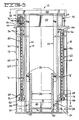
- Fig. 3 is a diagrammatic sectional view taken along lines III-III of Fig. 2 showing the fixed and movable uprights, lift jacks, and bearing assemblies of the present invention; and
- Fig. 4 is a diagrammatic sectional view of the lift mast assembly taken along lines IV-IVof Fig. 3with portions of the lift mast assembly broken out to show more clearly certain components and relationships.
- Referring to the drawings, a
lift mast assembly 10 has a fixedupright assembly 12 and a movableupright assembly 14. The fixedupright assembly 12 has a first upright 16 and a second upright 18. These first and secondfixed uprights fixed uprights 16 and 18 a preselected spaced apart distance one from the other and forms a rigid structure with these uprights. - The movable
upright assembly 14 has a first and second upright 24 and 26. Preferably the first and second movable uprights are interconnected by upper and lower tie structure assemblies 28 and 30. These upper and lower tie assemblies maintain the first and second movable uprights a preselected spaced apart distance and form a rigid structure with these uprights. The movableupright assembly 14 is mounted on and between the fixedupright assembly 12 and elevationally extensible relative thereto. The fixedupright assembly 12 is pivotly mounted on oneend portion 32 of alift truck 34 having a pair of spacedfront wheels 35 in any suitable well known applicable manner. - A
carriage assembly 36 of a type well known in the industry is mounted on the movableupright assembly 14 and elevationally positionable relative to the movable upright assembly. Preferably the carriage has an upper pair ofguide rollers 38 and a lower pair ofguide rollers 40 mounted thereon. One roller of each of the upper and lower pair is engageable with the first movable upright 26 and the other rollers of each of the upper and lower pair is engageable with the second movable upright 24. Although carriage rollers have specifically been taught in this preferred embodiment it is to be understood that other equivalents such as slider bearing blocks, strips, and the like which are known in the art are suitable substitutes. - The first and second fixed
uprights movable uprights web 42, 42' having first andsecond sides surface 47. Thesurface 47 of the first fixed and firstmovable uprights surface 47 of the second fixed andmovable uprights Surface 47 of the first fixed and firstmovable uprights lower bearing assembly surface 48 of the second fixed andmovable uprights lower bearing assembly assemblies lower bearing assemblies lower end portion upper bearing assembly 48 is connected to theupper end portion 56 of the first fixed upright 16 and the secondupper bearing assembly 52 is connected to theupper end portion 56 of the second fixed upright 18. The firstlower bearing assembly 50 is connected to thelower end portion 58 of the first movable upright 24 and the secondlower bearing assembly 54 is connected to thelower end portion 58 of the second movable upright 26. It is to be noted that although thelower bearing assemblies movable uprights lower bearing assemblies uprights lower bearing assemblies - First and
second lift jack tubular cylinder 64 and apiston rod 66 slideably disposed in the tubular cylinder. Thecylinders 64 each have alower end 68 and thepiston rods 66 each have anupper end portion 70. Thefirst lift jack 60 is mounted on one of the first fixed 16 and first movable 24 uprights and connected to the other of the first fixed 16 and first movable 24 uprights. Thesecond lift jack 62 is mounted on one of the second fixed 18 and second movable 26 uprights and connected to the other of the second fixed 18 and secondmovable uprights 26. Preferably thefirst lift jack 60 is mounted on thefirst fixed upright 16 at itslower end portion 58 and theupper end portion 70 of itspiston rod 66 is connected to the firstmovable upright 24. Similarly thesecond lift jack 62 is mounted on the second fixed upright 18 at itslower end portion 58 and theupper end portion 70 of the second lift jacks 62piston rod 66 is connected to the secondmovable upright 26. As best seen in Fig. 4, thefirst lift jack 60 is positioned between theweb 42 of the first fixedupright 16 and the web 42' of the firstmovable upright 24 and thesecond lift jack 62 is positioned between theweb 42 of the second fixedupright 18 and the web 42' of the secondmovable upright 26. Additionally, thefirst lift jack 60 is preferably located between thefirst side 44 and thesecond side 46 of theweb 42, 42' of either one or both of the first fixed 16 and first movable 24 uprights and thesecond lift jack 62 is preferably located between the first andsecond sides web 42, 42' either or both the second fixed and secondmovable uprights - As shown in the drawings and particularly the drawings of Figs. 3 and 4, a
first bracket assembly 72 is provided for mounting thefirst lift jack 60 on the first fixedupright 16 and asecond bracket assembly 74 is provided for mounting thesecond lift jack 62 on the second fixedupright 18. Thefirst bracket 72 is preferably connected to theweb 42 of the first fixedupright 16 and extends a preselected distance in a direction from thesurface 47 toward theweb 42 of the first 24 and second fixed 18 upright. The second bracket assembly similarly, is connected toweb 42 of the second fixedupright 18 and extends a preselected distance in a direction from thesurface 47 toward the web 42' of the second movable 26 and first fixed 16 upright. It is to be noted that although the brackets were described as being two separate members it is to be understood that a single structure connected to theweb 42 of both fixed uprights which extends transversely between these fixed uprights would be a suitable equivalent. - The
lower end 68 ofcylinder 64 of thefirst lift jack 60 is connected to thefirst bracket assembly 72 in any conventional suitable manner, for example such as by a pin, bolt, or ball joint and thelower end 68 ofcylinder 64 of thesecond lift jack 62 is connected to thesecond bracket assembly 74 in a like manner. Preferably this connection will permit a limited amount of pivotable movement of each of the cylinders about their respective bracket connections. - A
first sheave 76 is rotatably connected to theupper end portion 70 ofpiston rod 66 of the first lift jack and in a like manner asecond sheave 78 is rotatably connected to theupper end portion 70 ofpiston rod 66 of thesecond lift jack 62. A firstflexible tension member 80 having a first andsecond end carriage assembly 36 and at the second end to the fixed upright assembly. It is to be noted that the first sheave and first flexible tension members are at least positioned between thewebs 42, 42' of the first fixed 16 and first movable 24 uprights. A second flexible tension member 86 (Fig. 1) having afirst end 88 and asecond end 90 is trained over thesecond sheave 78 and connected at thefirst end 88 to thecarriage assembly 36 and at thesecond end 90 to the fixedupright assembly 12. it is to be noted that thesecond sheave 78 and second flexible tension member are at least partially located between thewebs 42, 42' of the second fixed 18 and second movable 26 uprights with the moveable uprights in the lowered position. - First fixed
upright 16 and second fixedupright 18 each have a first 92 and second 94 rear flange mounted thereon. The firstrear flanges 92 are each positioned on their respective fixeduprights 16 and 18 a preselected distance from thesecond side 46 of theirrespective webs 42 and the secondrear flanges 94 are positioned on their respective fixeduprights 16 and 18 a preselected distance from thesecond side 46 of theirrespective webs 42. The distance between thesecond side 46 and its adjacent firstrear flange 92 being smaller in magnitude than the distance between the adjacent second rear flange and the second side. The first and secondrear flanges rear flanges rear flange upright 18 face one another. Preferably, the first and second rear flanges are mounted on thesurface 47 of theweb 42 of their respective first and second fixeduprights rear flanges upright 16 are substantially parallel along their length and the first and secondrear flanges upright 18 are parallel along their length. - A first movable upright rear flange 96 and a second movable upright
rear flange 98 each have a first andsecond surface second side second side 46 of the web 42' of the firstmovable upright 24 and the second movable uprightrear flange 98 is connected to thesecond side 46 of the web 42' of the secondmovable upright 26. The first and second movable upright rear flanges are preferably elongate rectangular shaped members which extend the full length of the adjacent web 42'. - A first movable upright
front flange 108 and a second movable uprightfront flange 110 are connected to the firstmovable upright 24 and secondmovable upright 26, respectively. Specifically, the first movable uprightfront flange 108 is a substantially elongate rectangular member connected to the web 42' of the firstmovable upright 24 at a preselected distance spaced from the first movable upright rear flange 96. Similarly, the second movable uprightfront flange 110 is an elongate rectangular member and is connected to the web 42' of the secondmovable upright 26 at a preselected distance spaced from the second . movable uprightrear flange 98. The first and second movable uprightfront flanges rear flanges 96, 98. The first and second upper andlower bearing assemblies movable uprights upper bearing assemblies first surface 100 andsecond side 106 of their respectively adjacentmovable uprights lower bearing assemblies rear flanges 92. - Referring particularly to Figs. 3 and 4, the
cylinders 64 of each of the first and second lift jacks 60 and 62 have a preselected diameter "D" and the distance "E" between the web of the first fixedupright 16 and first movable upright is greater in magnitude at the cylinder mounted location than the diameter "D" of the first cylinder and the distance "E" between the web of the second fixed and secondmovable uprights flexible tension members respective webs 42, 42' of the adjacent pairs of fixed and movable uprights and thereby improving the operator's visibility. - With reference to Fig. 4, the
web 42 of first and second fixeduprights movable uprights station 114 and the lines of sight "L" (see Fig. 2) from the operator's station for a given operator norm. Preferably the angle of each of thewebs 42 of the fixeduprights movable upright web 42 of the first fixedupright 16 is spaced a preselected first distance from the web 42' of the firstmovable upright 24 at the websecond side 46 and a second preselected distance from the web 42' of the first movable upright at the websfirst side 44. Likewise theweb 42 of the second fixedupright 18 is spaced an equal first preselected distance from the web 42' of the secondmovable upright 26 at the web's second side and the same second preselected distance from the web 42' of the secondmovable upright 26 at the web'sfirst side 44. Preferably this first preselected distance is smaller in magnitude than the second preselected distance. - In operation with reference to the drawings, elevational movement of the
movable upright assembly 14 along the fixedupright assembly 12 and elevational movement of the carriage along the guideways provided by the front andrear flanges 110forthe carriage rollers rods 66 will cause extension of themovable upright assembly 14 through the previously discussed movable upright and rod connection and elevational movement of thecarriage 36 relative to themovable upright assembly 14 is achieved through the connection of thesheaves flexible tension members - Since the
first lift jack 60 and associatedfirst sheave 76 and firstflexible tension member 80 are nested between thewebs 42, 42' of the first fixed 16 and firstmovable upright 24 and thesecond lift jack 62 and associatedsecond sheave 78 and secondflexible tension member 86 are nested between thewebs 42, 42' of the second fixed 18 and second movable 26 uprights the obstruction relative to the line of sight of the vehicle operator is minimized. - Since a pair of lift jacks 60 and 62 are provided, as compared to a single lift jack, the diameter of
cylinder 66 is substantially reduced which permits thewebs 42, 42' of the adjacent fixed and movable uprights to be spaced a closer distance apart than previously permitted. Further utilizing thebearing assemblies webs 42 of the fixeduprights movable uprights webs 42 are placed is parallel to the line of sight of the operator. - Locating the lift jacks 60 and 62 between the first and second sides of the
webs 42,42' of either one of the respectively adjacent fixed andmovable uprights - Finally, due to the compactness of the
mast assembly 10, the mast assembly may be located between thefront wheels 35 without reducing the visibility, shortening the lift jacks 60, 62, or reducing overall lift height. - Other aspects, objects and advantages of the invention can be readily obtained from a study of the drawings, disclosure and appended claims.
Claims (11)
Applications Claiming Priority (1)
| Application Number | Priority Date | Filing Date | Title |
|---|---|---|---|
| PCT/US1982/000354 WO1983003406A1 (en) | 1982-03-22 | 1982-03-22 | Lift mast assembly |
Publications (3)
| Publication Number | Publication Date |
|---|---|
| EP0104171A1 EP0104171A1 (en) | 1984-04-04 |
| EP0104171A4 EP0104171A4 (en) | 1985-09-18 |
| EP0104171B1 true EP0104171B1 (en) | 1989-05-10 |
Family
ID=22167877
Family Applications (1)
| Application Number | Title | Priority Date | Filing Date |
|---|---|---|---|
| EP82901388A Expired EP0104171B1 (en) | 1982-03-22 | 1982-03-22 | Lift mast assembly |
Country Status (7)
| Country | Link |
|---|---|
| US (1) | US4441585A (en) |
| EP (1) | EP0104171B1 (en) |
| JP (1) | JPS59500414A (en) |
| CA (1) | CA1179646A (en) |
| DE (1) | DE3279681D1 (en) |
| NO (1) | NO160430C (en) |
| WO (1) | WO1983003406A1 (en) |
Cited By (1)
| Publication number | Priority date | Publication date | Assignee | Title |
|---|---|---|---|---|
| DE3532827A1 (en) * | 1984-09-14 | 1986-03-27 | Linde Ag, 6200 Wiesbaden | Repeatedly extendable lifting frame |
Families Citing this family (10)
| Publication number | Priority date | Publication date | Assignee | Title |
|---|---|---|---|---|
| US5000293A (en) * | 1988-11-03 | 1991-03-19 | Clark Equipment Company | Upright for lift truck |
| US4949816A (en) * | 1988-11-03 | 1990-08-21 | Clark Equipment Company | Upright for lift truck |
| EP0574615B1 (en) * | 1992-06-15 | 1996-02-07 | R. Blom Beheer B.V. | Telescopic upright for a lift truck |
| SE523505C2 (en) * | 2000-03-03 | 2004-04-27 | Smv Lifttrucks Ab | Device for counterbalance trucks |
| GB2387376B (en) * | 2002-04-10 | 2005-12-21 | Lansing Linde Ltd | Industrial trucks having lifting masts |
| US7096999B2 (en) * | 2003-08-05 | 2006-08-29 | The Raymond Corporation | Mast construction for a lift truck |
| DE202007003491U1 (en) * | 2007-03-08 | 2007-05-10 | Jungheinrich Aktiengesellschaft | Bearing arrangement for lift chain roller, has steel frame attached to middle rod profile or to cross bar, which is connected to middle rod profile by welding, where profile is supported at upper end of roller |
| US8757326B2 (en) | 2011-10-12 | 2014-06-24 | Crown Equipment Corporaton | Pallet stops for lift trucks |
| US10087059B1 (en) * | 2017-01-11 | 2018-10-02 | Custom Mobile Equipment, Inc. | Double column boom attachment for a lift truck |
| CN107931453B (en) * | 2017-11-24 | 2023-10-17 | 安徽鲲鹏装备模具制造有限公司 | Bottom plate pre-riveting equipment of refrigerator liner |
Family Cites Families (10)
| Publication number | Priority date | Publication date | Assignee | Title |
|---|---|---|---|---|
| US1899751A (en) * | 1929-12-20 | 1933-02-28 | Westinghouse Elec Elevator Co | Elevator guide |
| US2456320A (en) * | 1947-02-24 | 1948-12-14 | Ross Carrier Company | Lift truck |
| US3127956A (en) * | 1954-02-25 | 1964-04-07 | Clark Equipment Co | Lift truck |
| US3394778A (en) * | 1966-11-25 | 1968-07-30 | Eaton Yale & Towne | Lift truck mast assembly |
| US4030568A (en) * | 1976-03-24 | 1977-06-21 | Caterpillar Tractor Co. | High visibility mast for lift trucks |
| US4219302A (en) * | 1978-02-13 | 1980-08-26 | Towmotor Corporation | Cylinder arrangement for raising a carriage and uprights of a mast |
| WO1980000434A1 (en) * | 1978-08-17 | 1980-03-20 | Bushiki Kaisha Toyoda Jidoshok | Device for loading and unloading lift truck |
| US4238004A (en) * | 1979-07-18 | 1980-12-09 | Cascade Corporation | Hidden chain assembly for lift truck mast |
| JPS5637994A (en) * | 1979-09-03 | 1981-04-11 | Toyoda Automatic Loom Works | Mast device in fork lift |
| WO1981002566A1 (en) * | 1980-03-10 | 1981-09-17 | R Stedman | Extra lift mast for lift trucks |
-
1982
- 1982-03-22 WO PCT/US1982/000354 patent/WO1983003406A1/en active IP Right Grant
- 1982-03-22 DE DE8282901388T patent/DE3279681D1/en not_active Expired
- 1982-03-22 US US06/375,114 patent/US4441585A/en not_active Expired - Fee Related
- 1982-03-22 JP JP57501429A patent/JPS59500414A/en active Pending
- 1982-03-22 EP EP82901388A patent/EP0104171B1/en not_active Expired
- 1982-12-17 CA CA000417971A patent/CA1179646A/en not_active Expired
-
1983
- 1983-10-07 NO NO83833658A patent/NO160430C/en unknown
Cited By (2)
| Publication number | Priority date | Publication date | Assignee | Title |
|---|---|---|---|---|
| DE3532827A1 (en) * | 1984-09-14 | 1986-03-27 | Linde Ag, 6200 Wiesbaden | Repeatedly extendable lifting frame |
| DE3532827C2 (en) * | 1984-09-14 | 1995-11-16 | Linde Ag | Multiple extendable mast |
Also Published As
| Publication number | Publication date |
|---|---|
| EP0104171A4 (en) | 1985-09-18 |
| CA1179646A (en) | 1984-12-18 |
| WO1983003406A1 (en) | 1983-10-13 |
| NO833658L (en) | 1983-10-13 |
| NO160430C (en) | 1989-04-19 |
| NO160430B (en) | 1989-01-09 |
| US4441585A (en) | 1984-04-10 |
| DE3279681D1 (en) | 1989-06-15 |
| JPS59500414A (en) | 1984-03-15 |
| EP0104171A1 (en) | 1984-04-04 |
Similar Documents
| Publication | Publication Date | Title |
|---|---|---|
| EP0104171B1 (en) | Lift mast assembly | |
| JPH0111680Y2 (en) | ||
| US4030568A (en) | High visibility mast for lift trucks | |
| US3561628A (en) | Load handling in fork-lift trucks movable fork cover for forklift truck | |
| US3841442A (en) | Lift truck upright | |
| KR880003809A (en) | Rear platform lift | |
| US20140219760A1 (en) | Reach assembly with offset pivot points for a materials handling vehicle | |
| US4759452A (en) | Articulated load bearing wear pad assembly | |
| US3998346A (en) | Material handling apparatus | |
| CA1089415A (en) | Cylinder arrangement for raising a carriage and uprights of a mast | |
| US4356893A (en) | Load lifting carriage and mast assembly | |
| CA1288078C (en) | Lift truck mast structure | |
| US3777853A (en) | Hose guide for lift truck | |
| US3727781A (en) | Lift truck load lifting mechanism | |
| US5816768A (en) | Reach type forklift truck with a mast assembly of reduced jerking motion | |
| WO1983001434A1 (en) | Lift mast assembly | |
| GB2077224A (en) | Load handling mast for a truck | |
| US20040037687A1 (en) | Transport system for the transport of components | |
| KR102368663B1 (en) | wire guiding apparatus for crane | |
| US4276961A (en) | Mast and carriage assembly | |
| US4366883A (en) | Equalizing system for load lifting apparatus | |
| JPS6011030Y2 (en) | Forklift cargo handling equipment | |
| CN116101940B (en) | Mining explosion-proof rubber wheel type unit bracket forklift truck | |
| CN218145523U (en) | Slide way structure for relay type dual-drive single-cylinder bolt telescopic system | |
| EP0050110A4 (en) | Load lifting carriage and mast assembly. |
Legal Events
| Date | Code | Title | Description |
|---|---|---|---|
| PUAI | Public reference made under article 153(3) epc to a published international application that has entered the european phase |
Free format text: ORIGINAL CODE: 0009012 |
|
| AK | Designated contracting states |
Kind code of ref document: A1 Designated state(s): DE FR GB NL SE |
|
| 17P | Request for examination filed |
Effective date: 19840404 |
|
| RAP1 | Party data changed (applicant data changed or rights of an application transferred) |
Owner name: CATERPILLAR INDUSTRIAL INC. |
|
| 17Q | First examination report despatched |
Effective date: 19860524 |
|
| D17Q | First examination report despatched (deleted) | ||
| GRAA | (expected) grant |
Free format text: ORIGINAL CODE: 0009210 |
|
| AK | Designated contracting states |
Kind code of ref document: B1 Designated state(s): DE FR GB NL SE |
|
| REF | Corresponds to: |
Ref document number: 3279681 Country of ref document: DE Date of ref document: 19890615 |
|
| ET | Fr: translation filed | ||
| PGFP | Annual fee paid to national office [announced via postgrant information from national office to epo] |
Ref country code: FR Payment date: 19900209 Year of fee payment: 9 |
|
| PGFP | Annual fee paid to national office [announced via postgrant information from national office to epo] |
Ref country code: SE Payment date: 19900227 Year of fee payment: 9 |
|
| PGFP | Annual fee paid to national office [announced via postgrant information from national office to epo] |
Ref country code: GB Payment date: 19900228 Year of fee payment: 9 |
|
| PLBE | No opposition filed within time limit |
Free format text: ORIGINAL CODE: 0009261 |
|
| STAA | Information on the status of an ep patent application or granted ep patent |
Free format text: STATUS: NO OPPOSITION FILED WITHIN TIME LIMIT |
|
| PGFP | Annual fee paid to national office [announced via postgrant information from national office to epo] |
Ref country code: DE Payment date: 19900313 Year of fee payment: 9 |
|
| PGFP | Annual fee paid to national office [announced via postgrant information from national office to epo] |
Ref country code: NL Payment date: 19900331 Year of fee payment: 9 |
|
| 26N | No opposition filed | ||
| PG25 | Lapsed in a contracting state [announced via postgrant information from national office to epo] |
Ref country code: FR Effective date: 19901130 |
|
| REG | Reference to a national code |
Ref country code: FR Ref legal event code: ST |
|
| PG25 | Lapsed in a contracting state [announced via postgrant information from national office to epo] |
Ref country code: GB Effective date: 19910322 |
|
| PG25 | Lapsed in a contracting state [announced via postgrant information from national office to epo] |
Ref country code: SE Effective date: 19910323 |
|
| PG25 | Lapsed in a contracting state [announced via postgrant information from national office to epo] |
Ref country code: NL Effective date: 19911001 |
|
| NLV4 | Nl: lapsed or anulled due to non-payment of the annual fee | ||
| GBPC | Gb: european patent ceased through non-payment of renewal fee | ||
| PG25 | Lapsed in a contracting state [announced via postgrant information from national office to epo] |
Ref country code: DE Effective date: 19920101 |
|
| EUG | Se: european patent has lapsed |
Ref document number: 82901388.7 Effective date: 19911009 |