EP0104151A2 - A device for the non-destructive testing of the internal stress state of heat tempered plate glass - Google Patents
A device for the non-destructive testing of the internal stress state of heat tempered plate glass Download PDFInfo
- Publication number
- EP0104151A2 EP0104151A2 EP83830178A EP83830178A EP0104151A2 EP 0104151 A2 EP0104151 A2 EP 0104151A2 EP 83830178 A EP83830178 A EP 83830178A EP 83830178 A EP83830178 A EP 83830178A EP 0104151 A2 EP0104151 A2 EP 0104151A2
- Authority
- EP
- European Patent Office
- Prior art keywords
- radiation
- signal
- polarization
- optical
- plate
- Prior art date
- Legal status (The legal status is an assumption and is not a legal conclusion. Google has not performed a legal analysis and makes no representation as to the accuracy of the status listed.)
- Granted
Links
Images

Classifications
-
- G—PHYSICS
- G01—MEASURING; TESTING
- G01L—MEASURING FORCE, STRESS, TORQUE, WORK, MECHANICAL POWER, MECHANICAL EFFICIENCY, OR FLUID PRESSURE
- G01L1/00—Measuring force or stress, in general
- G01L1/24—Measuring force or stress, in general by measuring variations of optical properties of material when it is stressed, e.g. by photoelastic stress analysis using infrared, visible light, ultraviolet
- G01L1/241—Measuring force or stress, in general by measuring variations of optical properties of material when it is stressed, e.g. by photoelastic stress analysis using infrared, visible light, ultraviolet by photoelastic stress analysis
-
- G—PHYSICS
- G01—MEASURING; TESTING
- G01N—INVESTIGATING OR ANALYSING MATERIALS BY DETERMINING THEIR CHEMICAL OR PHYSICAL PROPERTIES
- G01N21/00—Investigating or analysing materials by the use of optical means, i.e. using sub-millimetre waves, infrared, visible or ultraviolet light
- G01N21/17—Systems in which incident light is modified in accordance with the properties of the material investigated
- G01N21/21—Polarisation-affecting properties
Definitions
- the present invention refers to a device for measuring the mechanical stress in a transparent object, in particular heat tempered glass.
- This relative delay 6 can be directly correlated to the internal stress state of the test material according to Maxwell's theory.
- the measurement method is no longer objective since cases of high stress involve the evaluation of the interference order by means of subjective evaluation of the colors of the interference fringe.
- the precision of the method also decreases, since determing the color effects necessary for evaluating the interference order prevents the use of monochromatic light, with consequent loss of resolution and precison, even for low stresses.
- U.S. patent n. 3,589,812 describes a method for measuring the delay 6 by means of technique for analyzing the polarization which leads to a one point response, variable in intensity according to a sinusoidal type law. This response is correlated mathematically correlated with the delay ⁇ .
- a series of simplifying hypotheses allows the value 6 to be determined numerically from the intensity measurement.
- the aim of the present invention is to provide a device for the non-destructive testing of heat tempered plate glass which combines high intrinsic precision with the possiblitity of completely automated testing.
- a common characteristic of the technology for tempering glass by means of heat exchange is to place high compression values along the edges 6f the plate, which can be correlated, as a function of the specific characteristics 6f the technology used, with the state of tempering of the plate itself.
- the presence of this compression can readily be seen by means of oolariscopy, and may be quantified by counting and evaluating the interference fringes.
- Typical values of this compression state of the tempered glass range from 40 to 70 MPa, that is above the values for which the GARDON method can be used, without requiring counting the fringes.
- an apparatus which uses monechromatic light with a wavelength in the near infrared in order to measure the quantity of radiation passing through the glass plate, polarized in a polarizing plane.
- the polarization component is measured of the radiation coming from a point of the plate at 9 0 ° with respect to the polarization plane of the incoming radiation.
- the determination is really a direct measurement of the intensity of the radiation, unlike the previous technique which was directed toward measuring the relative delay between two components of polarized visible light, which reauired evaluation of the interference order.
- the object of the present invention is a device for non-destructive testing of the internal stress state of heat tempered plate glass, involving: a source of monochromatic infrared radiation which emits said radiation along an optic axis; an infrared light sensor placed on said optic axis; first optical concentration means to concentrate the radiation emitted from said source on a point of a glass plate, situated on said optic axis; first optical polarization means to polarize in a polarization plane the radiation emitted from said source and concentrated 5 on said point of the glass plate by said first concentration device; second optical concentration means to concentrate the radiation coming out from said point, after having passed through the glass plate, on said infrared radiation intensity detector; second optical polarization means to polarize said radiation coming from said point and concentrated on said detector by said second concentration device, is a polarization plane rotated 90 D with respect to said polarization plane of the incoming polarized radiation; comparator means to compare a signal indicating the intensity of the radiation received from said detector with a determined
- the present invention uses a wave length longer than that used in previous techniques, to substantially modify the spectral interval of radiation, so that direct instrumental measurement of the delay value 6 represents the stress state.
- the use of invisible infrared radiation makes it unnecessary to count the interference fringe since it shifts the maximum practical limit of measurable stress from approximately 40 mPa to approximately 100 mPa for a 3 mm thick plate.
- the apparatus for measuring the stress in the edge of a heat tempered glass plate consists of a source of infrared radiation S which emits infrared radiation in the direction of the optical axis O.
- the radiation is collected by a lens L1 and converged toward a point F on a glass plate V, placed on the optical axis O and on the focal plane of the lens L1.
- An infrared polarizer P1 ensures that the incident radiation on point F is polarized in a certain plane.
- the radiation After passing through the thickness of the plate V, the radiation is collected by a lens L2 and made to converge on an infrared sensor R.
- the radiation beam is passed through an infrared polarizer P2 which polarizes it in a plane rotated 90 0 with respect to polarizer 1.
- the glass plate sample V is placed in focal area common tb both lenses L1 and L2.
- collimators may be used instead of lenses to increase the precision of the meansurement.
- the suitably amplified electrical signal from the sensor R is compared electronically with a prefixed value which represents the minimum experimental value for acceptable edge stresses.
- This comparation and threshold calibration may be performed by known methods, with standard electronic components.
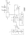
- Figure 2 shows an example of the realization of an electronic system which processes and utilizes the signals obtained with the device in figure 1.
- Figure 2 shows a differentiator group in which the electrical signal from sensor R is differentiated to be sent to an ampilifier 2.
- a circuit for generating the threshold signals is indicated with 3.
- the threshold signal may be controlled by means of an instrument 4 after having been amplified in an amplifier 5, and the circuit of the instrument 4 may also be used to control the segnal emanating from the differentiatior 1, by means of switching a switch 6.
- the threshold signal prefixed by means of the circuit from threshold generator 3 is compared with the signal from the amplifier 2 by means of a comparator circuit 7 which transmits to a logic state detected, on the basis of a comparison of said two signals.
- the logical circuit 8 signals the state determined and activates signalizing devices which signal whether the stress state of the glass plate being tested is within the prescribed limits.
- the segnalizing devices may consist of red light (LR) or green light (LV) LED which light up to approve or reject the test plate.
- the OUT terminal is indicated as a terminal to measure the signal in case it is eventually used, and the IN terminal indicates a terminal which permits, by means of switch 9, the apparatus to be placed in operation when a class plate to be tested is introduced in it.
- the liqht source S and the sensor R may also consist of infrared active LED diodes, with the result that the entire system is very simple to manufacture and very reliable to operate.
Landscapes
- Physics & Mathematics (AREA)
- General Physics & Mathematics (AREA)
- Health & Medical Sciences (AREA)
- Life Sciences & Earth Sciences (AREA)
- Chemical & Material Sciences (AREA)
- Analytical Chemistry (AREA)
- Biochemistry (AREA)
- General Health & Medical Sciences (AREA)
- Immunology (AREA)
- Pathology (AREA)
- Investigating Or Analysing Materials By Optical Means (AREA)
- Investigating Materials By The Use Of Optical Means Adapted For Particular Applications (AREA)
- Investigating Or Analyzing Materials Using Thermal Means (AREA)
Abstract
Description
- The present invention refers to a device for measuring the mechanical stress in a transparent object, in particular heat tempered glass.
- Current state of the art measurement methods involve analysis of the internal stress state by measuring the relative delay δ between the two components of polarized light into which electromagnetic radiation is divided when it passes through stressed transparent material.
- This
relative delay 6 can be directly correlated to the internal stress state of the test material according to Maxwell's theory. - Typical applications of these methods can be found in the literature and are widely documented.
- An article by GARDON, BAYMA and WARNICK in Experimental Mechanics, November 1966, entitled 'A recording photoelastic stress meter' describes a method and a device for measuring the mechanical stress in tempered glass, using a Babinet type compensation technique in which the quantitative measurement of the delay depends on the determination by the operator of the fringe order. Therefore, when the delay is greater than the wavelength of the impinging radiation, it is necessary to establish how many multiples(fringes) of the wavelength should be added to the instrumentally determined value.
- This makes it impossible to automate the instrument, except for the case of low stress ( <40 MPa) typical for example of annealed glass (float glass, etc.), and excludes that of tempered glass.
- Therefore, the measurement method is no longer objective since cases of high stress involve the evaluation of the interference order by means of subjective evaluation of the colors of the interference fringe.
- The precision of the method also decreases, since determing the color effects necessary for evaluating the interference order prevents the use of monochromatic light, with consequent loss of resolution and precison, even for low stresses.
- U.S. patent n. 3,589,812 describes a method for measuring the
delay 6 by means of technique for analyzing the polarization which leads to a one point response, variable in intensity according to a sinusoidal type law. This response is correlated mathematically correlated with the delay δ. - A series of simplifying hypotheses allows the
value 6 to be determined numerically from the intensity measurement. - The U.S. patent n. 3,589,812 cited above involves refinement of the experimental techniques to make the measurement as reliable as-possible. This measurement is effected using a traditional type light source. However, the problems related to the precision of the instrument for high stress values still remain. For transmission measurements in particular, evaluation of the interference order remains indispensable.
- In practice, in the current state of the art, the most simple and reliable system for testing the stress state of tempered glass consists of breaking the glass and examining the fracture configuration, so as to have statistical control during production of tempered plate glass.
- The aim of the present invention is to provide a device for the non-destructive testing of heat tempered plate glass which combines high intrinsic precision with the possiblitity of completely automated testing.
- A common characteristic of the technology for tempering glass by means of heat exchange is to place high compression values along the edges 6f the plate, which can be correlated, as a function of the specific characteristics 6f the technology used, with the state of tempering of the plate itself. The presence of this compression can readily be seen by means of oolariscopy, and may be quantified by counting and evaluating the interference fringes.
- Typical values of this compression state of the tempered glass range from 40 to 70 MPa, that is above the values for which the GARDON method can be used, without requiring counting the fringes.
- For the type of measurement in question, the method described in the U.S. patent cited above presents the same difficulties.
- From the preceding discussion, it is obvlious that previous systems inherently involved the use of wavelenghhs of light in the visible range which was also non-monochromatic, in order to measure the relative delay δ mentioned above.
- According to the present invention, an apparatus is provided which uses monechromatic light with a wavelength in the near infrared in order to measure the quantity of radiation passing through the glass plate, polarized in a polarizing plane.
- It has been surprisingly discovered that even the stress state in one point of a heat tempered glass plate can be determined by means of a simple measurement of the variation of the polarization of the radiation passing through said plate, when infrared radiation is used.
- More precisely, the polarization component is measured of the radiation coming from a point of the plate at 90° with respect to the polarization plane of the incoming radiation.
- In this way, the determination is really a direct measurement of the intensity of the radiation, unlike the previous technique which was directed toward measuring the relative delay between two components of polarized visible light, which reauired evaluation of the interference order.
- The object of the present invention is a device for non-destructive testing of the internal stress state of heat tempered plate glass, involving: a source of monochromatic infrared radiation which emits said radiation along an optic axis; an infrared light sensor placed on said optic axis; first optical concentration means to concentrate the radiation emitted from said source on a point of a glass plate, situated on said optic axis; first optical polarization means to polarize in a polarization plane the radiation emitted from said source and concentrated 5 on said point of the glass plate by said first concentration device; second optical concentration means to concentrate the radiation coming out from said point, after having passed through the glass plate, on said infrared radiation intensity detector; second optical polarization means to polarize said radiation coming from said point and concentrated on said detector by said second concentration device, is a polarization plane rotated 90D with respect to said polarization plane of the incoming polarized radiation; comparator means to compare a signal indicating the intensity of the radiation received from said detector with a determined threshold signal; and segnalization means to signal when said intensity is greater or less than said pre-established threshold value.
- It should be noted that the present invention uses a wave length longer than that used in previous techniques, to substantially modify the spectral interval of radiation, so that direct instrumental measurement of the
delay value 6 represents the stress state. - In particular, the use of invisible infrared radiation (for example, near infrared of 4.5 µ) makes it unnecessary to count the interference fringe since it shifts the maximum practical limit of measurable stress from approximately 40 mPa to approximately 100 mPa for a 3 mm thick plate.
- The advantages arising from this system are several:
- Elimination of the need to evaluate the interference order;
- Conseguent elimination of the subjectivity of this evaluation;
- Automation of the measurement;
- Use of monochromatic infrared sources of low energy expenditure (LED);
- Improved resolution due to the use of monochromatic sources;
- Use of standard components;
- Less dependence on electromaghetic radiation disturbances in the environment, the only remaining source of this radiation being incandescent lights, although to a limited degree.
- The present invention will be described below in one of its preferred embodiments, with reference to the attached drawings, in which:
- figure 1 shows an optical scheme of the device according to the invention;
- figure 2 shows a scheme of the circuit for processing and utilizing the signals obtained from a device as shown in figure 1.
- As shown in figure 1, the apparatus for measuring the stress in the edge of a heat tempered glass plate consists of a source of infrared radiation S which emits infrared radiation in the direction of the optical axis O. The radiation is collected by a lens L1 and converged toward a point F on a glass plate V, placed on the optical axis O and on the focal plane of the lens L1. An infrared polarizer P1 ensures that the incident radiation on point F is polarized in a certain plane. After passing through the thickness of the plate V, the radiation is collected by a lens L2 and made to converge on an infrared sensor R. The radiation beam is passed through an infrared polarizer P2 which polarizes it in a plane rotated 900with respect to polarizer 1.
- As shown, the glass plate sample V is placed in focal area common tb both lenses L1 and L2. Obviously, collimators may be used instead of lenses to increase the precision of the meansurement.
- The suitably amplified electrical signal from the sensor R is compared electronically with a prefixed value which represents the minimum experimental value for acceptable edge stresses. This comparation and threshold calibration may be performed by known methods, with standard electronic components.
- Figure 2 shows an example of the realization of an electronic system which processes and utilizes the signals obtained with the device in figure 1.
- Figure 2 shows a differentiator group in which the electrical signal from sensor R is differentiated to be sent to an
ampilifier 2. - A circuit for generating the threshold signals is indicated with 3. The threshold signal may be controlled by means of an instrument 4 after having been amplified in an
amplifier 5, and the circuit of the instrument 4 may also be used to control the segnal emanating from the differentiatior 1, by means of switching aswitch 6. - The threshold signal prefixed by means of the circuit from threshold generator 3 is compared with the signal from the
amplifier 2 by means of a comparator circuit 7 which transmits to a logic state detected, on the basis of a comparison of said two signals. - The logical circuit 8 signals the state determined and activates signalizing devices which signal whether the stress state of the glass plate being tested is within the prescribed limits. For example, the segnalizing devices may consist of red light (LR) or green light (LV) LED which light up to approve or reject the test plate. The OUT terminal is indicated as a terminal to measure the signal in case it is eventually used, and the IN terminal indicates a terminal which permits, by means of
switch 9, the apparatus to be placed in operation when a class plate to be tested is introduced in it. - The liqht source S and the sensor R may also consist of infrared active LED diodes, with the result that the entire system is very simple to manufacture and very reliable to operate.
- While a preferred embodiment of the invention has been described, it may of course be realized differently using known technologies, without going beyond the bounds of the present invention.
Claims (5)
Applications Claiming Priority (2)
| Application Number | Priority Date | Filing Date | Title |
|---|---|---|---|
| IT49143/82A IT1149352B (en) | 1982-09-21 | 1982-09-21 | DEVICE FOR NON-DESTRUCTIVE CONTROL OF THE TENSIONAL STATE OF THERMALLY TEMPERED GLASS SHEETS |
| IT4914382 | 1982-09-21 |
Publications (3)
| Publication Number | Publication Date |
|---|---|
| EP0104151A2 true EP0104151A2 (en) | 1984-03-28 |
| EP0104151A3 EP0104151A3 (en) | 1984-10-03 |
| EP0104151B1 EP0104151B1 (en) | 1986-12-03 |
Family
ID=11269768
Family Applications (1)
| Application Number | Title | Priority Date | Filing Date |
|---|---|---|---|
| EP83830178A Expired EP0104151B1 (en) | 1982-09-21 | 1983-09-19 | A device for the non-destructive testing of the internal stress state of heat tempered plate glass |
Country Status (5)
| Country | Link |
|---|---|
| US (1) | US4584476A (en) |
| EP (1) | EP0104151B1 (en) |
| DE (1) | DE3368125D1 (en) |
| ES (1) | ES525755A0 (en) |
| IT (1) | IT1149352B (en) |
Cited By (1)
| Publication number | Priority date | Publication date | Assignee | Title |
|---|---|---|---|---|
| EP0878702A3 (en) * | 1997-05-15 | 1999-04-28 | Saint-Gobain Vitrage | Method and device for measuring stresses in sheet glass by scattered light |
Families Citing this family (4)
| Publication number | Priority date | Publication date | Assignee | Title |
|---|---|---|---|---|
| DE3543632A1 (en) * | 1985-12-11 | 1987-06-19 | Hoechst Ag | METHOD AND DEVICE FOR DETERMINING THICKNESS AND / OR ORIENTATION CHANGES WITHIN AN OPTICALLY ACTIVE MATERIAL RAIL |
| CN1087424A (en) * | 1992-09-29 | 1994-06-01 | 昆士兰大学 | Defective in the glass that detects |
| US5929993A (en) * | 1998-03-03 | 1999-07-27 | J.A. Woollam Co. Inc. | Total film retardance monitoring system, and method of use |
| US7705995B1 (en) | 2004-12-20 | 2010-04-27 | J.A. Woollam Co., Inc. | Method of determining substrate etch depth |
Family Cites Families (6)
| Publication number | Priority date | Publication date | Assignee | Title |
|---|---|---|---|---|
| US1681991A (en) * | 1926-11-20 | 1928-08-28 | Corning Glass Works | Method of detecting and measuring strains |
| GB830313A (en) * | 1958-02-18 | 1960-03-16 | Zeiss Jena Veb Carl | Improvements in instruments for visualizing mechanical strain in opaque workpieces capable of transmitting infra-red light |
| FR1308015A (en) * | 1961-09-20 | 1962-11-03 | Saint Gobain | Method and devices for the examination of stresses in parts made of transparent material, for example glass |
| US3589812A (en) * | 1968-08-29 | 1971-06-29 | France Armed Forces | Processes and devices for measuring stresses within a transparent body for electromagnetic waves |
| US3818339A (en) * | 1972-08-14 | 1974-06-18 | Burroughs Corp | Amplitude comparison circuit |
| JPS55104743A (en) * | 1979-02-06 | 1980-08-11 | Fujitsu Ltd | Method for inspecting substrate |
-
1982
- 1982-09-21 IT IT49143/82A patent/IT1149352B/en active
-
1983
- 1983-09-19 US US06/534,627 patent/US4584476A/en not_active Expired - Fee Related
- 1983-09-19 DE DE8383830178T patent/DE3368125D1/en not_active Expired
- 1983-09-19 EP EP83830178A patent/EP0104151B1/en not_active Expired
- 1983-09-20 ES ES525755A patent/ES525755A0/en active Granted
Cited By (1)
| Publication number | Priority date | Publication date | Assignee | Title |
|---|---|---|---|---|
| EP0878702A3 (en) * | 1997-05-15 | 1999-04-28 | Saint-Gobain Vitrage | Method and device for measuring stresses in sheet glass by scattered light |
Also Published As
| Publication number | Publication date |
|---|---|
| IT8249143A0 (en) | 1982-09-21 |
| IT1149352B (en) | 1986-12-03 |
| US4584476A (en) | 1986-04-22 |
| EP0104151B1 (en) | 1986-12-03 |
| ES8500444A1 (en) | 1984-10-01 |
| ES525755A0 (en) | 1984-10-01 |
| DE3368125D1 (en) | 1987-01-15 |
| EP0104151A3 (en) | 1984-10-03 |
Similar Documents
| Publication | Publication Date | Title |
|---|---|---|
| CN102575985B (en) | For determining surveying instrument and the method for the characteristic of article and surface thereof | |
| US3565568A (en) | Method and apparatus for ascertaining geometric deviations from an ideal surface by optical means | |
| US4451147A (en) | Refractometer | |
| US4072426A (en) | Method and apparatus for determining the reflective properties of surfaces, especially coated surfaces | |
| KR20180008721A (en) | MEASURING APPARATUS AND METHOD FOR THIN FILM PROVIDED WITH TRANSPARENT SUBSTRATE | |
| SG50599A1 (en) | Optical gap measuring apparatus and method | |
| KR100474864B1 (en) | Method for measuring light transmittance and apparatus therefor | |
| US3744916A (en) | Optical film thickness monitor | |
| EP0104151B1 (en) | A device for the non-destructive testing of the internal stress state of heat tempered plate glass | |
| CN209085766U (en) | A kind of Spectral radiance measurement device | |
| CN104792732B (en) | A kind of refractometer of distribution of light sources from reference | |
| CN103323427A (en) | On-line self-calibration turbidity meter and turbidity detection method | |
| US20070002313A1 (en) | Process and apparatus for the identification of the tin side and the firing side in float glass | |
| RU2512659C2 (en) | Method to measure length of distribution of infra-red superficial plasmons on real surface | |
| US5131756A (en) | Test carrier analysis device | |
| US1681991A (en) | Method of detecting and measuring strains | |
| US3322024A (en) | Optical method for the inspection of a transparent object for deffects including comparing light energy at two stations | |
| CN115077865A (en) | Method for rapidly measuring absorption axis of polaroid | |
| US5764351A (en) | Method for the differential measurement of the angle of incidence of a luminous beam and device for implementing the method | |
| RU2202814C1 (en) | Cat's eye index meter for optoelectronic devices | |
| CN222926623U (en) | Turbidity meter | |
| CN105510296B (en) | The portable fluorescence Raman spectrum detection system that disappears | |
| CN218630225U (en) | Wafer recognition device | |
| JPS62159027A (en) | Oil deterioration level detection device | |
| RU2319941C1 (en) | Stress measuring detector |
Legal Events
| Date | Code | Title | Description |
|---|---|---|---|
| PUAI | Public reference made under article 153(3) epc to a published international application that has entered the european phase |
Free format text: ORIGINAL CODE: 0009012 |
|
| AK | Designated contracting states |
Designated state(s): BE CH DE FR GB LI LU |
|
| PUAL | Search report despatched |
Free format text: ORIGINAL CODE: 0009013 |
|
| AK | Designated contracting states |
Designated state(s): BE CH DE FR GB LI LU |
|
| 17P | Request for examination filed |
Effective date: 19841030 |
|
| 17Q | First examination report despatched |
Effective date: 19860422 |
|
| GRAA | (expected) grant |
Free format text: ORIGINAL CODE: 0009210 |
|
| AK | Designated contracting states |
Kind code of ref document: B1 Designated state(s): BE CH DE FR GB LI LU |
|
| REF | Corresponds to: |
Ref document number: 3368125 Country of ref document: DE Date of ref document: 19870115 |
|
| ET | Fr: translation filed | ||
| PG25 | Lapsed in a contracting state [announced via postgrant information from national office to epo] |
Ref country code: LU Free format text: LAPSE BECAUSE OF NON-PAYMENT OF DUE FEES Effective date: 19870930 |
|
| PLBE | No opposition filed within time limit |
Free format text: ORIGINAL CODE: 0009261 |
|
| STAA | Information on the status of an ep patent application or granted ep patent |
Free format text: STATUS: NO OPPOSITION FILED WITHIN TIME LIMIT |
|
| 26N | No opposition filed | ||
| PGFP | Annual fee paid to national office [announced via postgrant information from national office to epo] |
Ref country code: BE Payment date: 19890908 Year of fee payment: 7 |
|
| PGFP | Annual fee paid to national office [announced via postgrant information from national office to epo] |
Ref country code: LU Payment date: 19890913 Year of fee payment: 7 |
|
| PGFP | Annual fee paid to national office [announced via postgrant information from national office to epo] |
Ref country code: FR Payment date: 19890919 Year of fee payment: 7 |
|
| PGFP | Annual fee paid to national office [announced via postgrant information from national office to epo] |
Ref country code: CH Payment date: 19890927 Year of fee payment: 7 |
|
| PGFP | Annual fee paid to national office [announced via postgrant information from national office to epo] |
Ref country code: GB Payment date: 19890930 Year of fee payment: 7 |
|
| PGFP | Annual fee paid to national office [announced via postgrant information from national office to epo] |
Ref country code: DE Payment date: 19891030 Year of fee payment: 7 |
|
| PG25 | Lapsed in a contracting state [announced via postgrant information from national office to epo] |
Ref country code: GB Effective date: 19900919 |
|
| PG25 | Lapsed in a contracting state [announced via postgrant information from national office to epo] |
Ref country code: LI Effective date: 19900930 Ref country code: CH Effective date: 19900930 Ref country code: BE Effective date: 19900930 |
|
| BERE | Be: lapsed |
Owner name: SOCIETA ITALIANA VETRO SIV S.P.A. Effective date: 19900930 |
|
| GBPC | Gb: european patent ceased through non-payment of renewal fee | ||
| PG25 | Lapsed in a contracting state [announced via postgrant information from national office to epo] |
Ref country code: FR Effective date: 19910530 |
|
| REG | Reference to a national code |
Ref country code: CH Ref legal event code: PL |
|
| PG25 | Lapsed in a contracting state [announced via postgrant information from national office to epo] |
Ref country code: DE Effective date: 19910601 |
|
| REG | Reference to a national code |
Ref country code: FR Ref legal event code: ST |